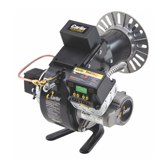
Carlin 201CRD Instruction Manual
Advanced oil burners, 2.5 to 5.5 gph & 3.0 to 7.0 gph
Hide thumbs
Also See for 201CRD:
- Instruction manual (89 pages) ,
- Installation and operating instructions manual (8 pages) ,
- Instruction manual (22 pages)
Table of Contents
Advertisement
Quick Links
Installer/servicer — Except where specifically stated other-
wise, this manual must be used only by a qualified service
technician. Failure to comply with this or other requirements
in this manual could result in severe personal injury, death or
substantial property damage.
User — Refer only to User care and maintenance on back
page for information regarding operation of this burner. The
burner Instruction Manual is intended only for your service
technician.The burner and heat exchanger must be inspected
and started at least annually by your service technician.
Instruction manual
Ratings
Input:
201CRD........................................2.50 to 5.00 GPH
301CRD (3¼'' air cone) ............ 3.00 to 6.00 GPH
301CRD (3½'' air cone) ............ 4.00 to 7.00 GPH
Fuels:
U.S. .................................... No. 1 or No. 2 Fuel oil
Canada....... No. 1 Stove oil or No. 2 Heating oil
Fuel unit:
.....................................................................Suntec
........................... 100 to 150
...........................................Factory set at 150
Electrical:
Power................................... 120V/60 Hz/1-Phase
Motor ...................Carlin PSC, 1/4 HP, 3450 RPM
Total current at 120V/60 Hz/1-Phase:
201CRD ............................Approx. 3.2 amps
301CRD ............................Approx. 3.2 amps
Ignition:
. Carlin Model 41000 electronic — 14,000 volts
Control:
.................................. U.L. primary safety control
Agencies:
..................................UL Listed (US and Canada)
©
Copyright 2004 — Carlin Combustion Technology, Inc.
Carlin Combustion Technology, Inc.
70 Maple Street
Ph 413-525-7700
T
800-989-2275
ECH SUPPORT
™
nozzle pressure
PSIG
PSIG
East Longmeadow, MA 01028
Fx 413-525-8306
carlincombustion.com
Advertisement
Table of Contents

Related Manuals for Carlin 201CRD


Summary of Contents for Carlin 201CRD
- Page 1 301CRD ......Approx. 3.2 amps User — Refer only to User care and maintenance on back Ignition: . Carlin Model 41000 electronic — 14,000 volts page for information regarding operation of this burner. The burner Instruction Manual is intended only for your service Control: ........
-
Page 2: Table Of Contents
Model 201CRD & 301CRD Advanced oil burners — Instruction manual PLEASE read this first . . . Contents Before installing or servicing . . . PLEASE read this first.............2 General information..............3 Codes and standards..............3 Should overheating occur: (1) Shut off the oil supply to the burner. -
Page 3: General Information
Codes and standards Certification 201CRD and 301CRD burners are U.L. listed for the U.S. and Canada, certified to comply with ANSI/UL 296, for use with #1 or #2 heating oil (per standard ASTM D396). Burner labels list compliance, when required, with special local, state or provincial approvals. -
Page 4: Prepare Site • Assemble Burner • Mount Burner
Model 201CRD & 301CRD Advanced oil burners — Instruction manual 2. Prepare site • assemble burner • mount burner Vent system Residential installation air openings Residential — Unconfined spaces (at least 7,000 cubic feet per GPH) General • An unconfined space means a room with at least 7,000 cubic feet volume for each GPH input (or 50 cubic feet per MBH) of all appliances in the room. - Page 5 Model 201CRD & 301CRD Advanced oil burners — Instruction manual 2. Prepare site • assemble burner • mount burner (continued) Combustion/ventilation air checklist Table 2 Minimum combustion/ventilation air openings The burner may operate successfully under momentary downdraft conditions, but sustained downdraft is unsafe.
- Page 6 Model 201CRD & 301CRD Advanced oil burners — Instruction manual 2. Prepare site • assemble burner • mount burner (continued) Verify combustion chamber Figure 1 Combustion chamber configurations, typical Chamber dimensions and construction • If retrofitting the burner to an appliance, install the burner in accordance with the appliance instruction manual, when available.
- Page 7 2. Prepare site • assemble burner • mount burner (continued) Table 3 201CRD and 301CRD Minimum combustion chamber dimensions (all dimensions in inches) - See Figure 1 for combustion chamber configurations – 7 – Carlin part number MN2301 Rev. 04/12/04...
- Page 8 Model 201CRD & 301CRD Advanced oil burners — Instruction manual 2. Prepare site • assemble burner • mount burner (continued) Inspect burner and components Figure 2 Standard adjustable flange (universal flange) General • Check the air tube length. Verify the usable length of the tube UTL will be long enough (see “Mount burner in appliance”).
- Page 9 Model 201CRD & 301CRD Advanced oil burners — Instruction manual 2. Prepare site • assemble burner • mount burner (continued) Mount burner in appliance Pedestal-mounted burners 1. Check the diameter of the appliance opening. If larger than 4½ inches, Welded flange-mounted burner rebuild the opening so the open is reduced to 4½...
-
Page 10: Prepare Burner
Model 201CRD & 301CRD Advanced oil burners — Instruction manual 3. Prepare burner Removing/installing head assembly Figure 7 Removing/inserting combustion head assembly Use care when handling burner components after the burner has been firing. Components can be hot and could cause severe personal injury. - Page 11 Model 201CRD & 301CRD Advanced oil burners — Instruction manual 3. Prepare burner (continued) Install nozzle/check electrodes Figure 9 Replacing the oil nozzle — 1. Loosen the clamp screw on the retention ring assembly (see Figure 9, 1 – Remove retention ring from nozzle adapter step 1).
- Page 12 Model 201CRD & 301CRD Advanced oil burners — Instruction manual 3. Prepare burner (continued) Set initial burner air settings Figure 12 Air band setting Combustion head (“A” dimension) 1. The combustion head adjusting screw is used to set the spacing between the retention ring and throttle ring (or air cone), regulating how much air passes around the retention ring.
- Page 13 Model 201CRD & 301CRD Advanced oil burners — Instruction manual 3. Prepare burner (continued) • Check all connections and joints to ensure they are air-tight. Table 4 Approximate air band and combustion head settings • Use flare fittings. DO NOT use compression fittings.
- Page 14 Model 201CRD & 301CRD Advanced oil burners — Instruction manual 3. Prepare burner (continued) One-line fuel system requirements Figure 15 Two-line fuel system • See Figure 14. • The standard burner fuel unit is a single-stage, 3450-RPM oil pump. Apply this fuel unit only on one-line systems where the fuel supply is on the same level with, or higher than, the burner.
- Page 15 Oil flow schematics / fuel unit connections Figure 18 201/301 burner with NYC-DAR pressure regulation kit • Figures 16, 17 and 18 show oil flow for Carlin 201 and 301 burners and Obtain pressure regulator kits for New York City Department show port functions for Suntec Model A, B, J and H pumps.
-
Page 16: Wire Burner • Start Burner
Figure 19 201CRD and 301CRD burners wiring using Carlin 40200 primary control (see appliance manual or separate wiring information for burner equipped with a primary control not covered in this manual) – 16 –... - Page 17 Model 201CRD & 301CRD Advanced oil burners — Instruction manual Start-up & operation Service & Troubleshooting Burner (control) will not come on Do not start the burner if the combustion chamber contains oil or oil vapor. No power to control •...
-
Page 18: 50200 Primary Control
Figure 20 201CRD and 301CRD burners wiring using Carlin 50200 primary control (see appliance manual or separate wiring information for burner equipped with a primary control not covered in this manual) – 18 –... - Page 19 Model 201CRD & 301CRD Advanced oil burners — Instruction manual Start-up & operation Model 50200 diagnostic LED’s – Red OFF – Red ON – Red FLASHING Do not start the burner if the combustion chamber contains oil or oil vapor.
-
Page 20: 60200 Primary Control
6. Make sure the burner and appliance are correctly wired and the line switch is properly fused for the load. Figure 21 201CRD and 301CRD burners wiring using Carlin 60200 primary control (see appliance manual or separate wiring information for burner equipped with a primary control not covered in this manual) –... - Page 21 Model 201CRD & 301CRD Advanced oil burners — Instruction manual Start-up & operation Model 60200 diagnostic LED’s – Red OFF – Red ON – Red FLASHING Do not start the burner if the combustion chamber contains oil or oil vapor.
-
Page 22: Adjustment And Verification
Model 201CRD & 301CRD Advanced oil burners — Instruction manual 5. Adjustment and verification Adjust burner using test instruments Firing against positive overfire pressure 1. Operate burner for 15 minutes before making final adjustments using test equipment. 1. Burner rating maximum inputs are based on operation with zero to slightly 2. -
Page 23: Annual Start-Up And Service
Model 201CRD & 301CRD Advanced oil burners — Instruction manual 5. Adjustment and verification 6. Annual start-up and service (cont.) Verify burner/appliance operation Annual start-up & service This burner must be started and serviced at least annually Check burner / appliance / controls by a qualified service technician. -
Page 24: Repair Parts
Model 201CRD & 301CRD Advanced oil burners — Instruction manual 7. Repair parts For parts not shown or listed, contact factory and/or check separate documentation supplied with appliance/burner unit. – 24 – Carlin part number MN2301 Rev. 04/12/04... - Page 25 Model 201CRD & 301CRD Advanced oil burners — Instruction manual 7. Repair parts (cont.inued) – 25 – Carlin part number MN2301 Rev. 04/12/04...
-
Page 26: Maintenance/Service Procedures
Model 201CRD & 301CRD Advanced oil burners — Instruction manual 8. Maintenance/service procedures Turn off power to appliance when servicing burner. Failure to comply • Orange to Blue (capacitor) wire ......5 to 7 ohms could result in severe personal injury, death or substantial property •... -
Page 27: Warranty
The repaired component or replacement part will be provided to the Customer freight prepaid by Carlin unless the returned part is determined by Carlin to be out of warranty or not to be defective, in which case it will be provided to the customer F.O.B., Carlin, East Longmeadow, Massachusetts. -
Page 28: User Care And Maintenance
Model 201CRD & 301CRD Advanced oil burners — Instruction manual 201CRD & 301CRD burner User care and maintenance Refer only to the information on this page, intended for your use. The remainder of this manual is intended only for your service technician.
Need help?
Do you have a question about the 201CRD and is the answer not in the manual?
Questions and answers