
Subscribe to Our Youtube Channel
Related Manuals for Satel SO-MF5


Summary of Contents for Satel SO-MF5
- Page 1 Keypad with MIFARE proximity card reader SO-MF5 Firmware version 1.01 so-mf5_en 03/24 SATEL sp. z o.o. • ul. Budowlanych 66 • 80-298 Gdańsk • POLAND tel. +48 58 320 94 00 www.satel.pl...
- Page 2 Changes, modifications or repairs not authorized by the manufacturer shall void your rights under the warranty. SATEL aims to continually improve the quality of its products, which may result in changes in their technical specifications and software. Current information about the changes being introduced is available on our website.
-
Page 3: Table Of Contents
CONTENTS Features ........................... 4 Description ........................5 Function keys......................5 PUSH IN terminals ...................... 5 Enclosure opening tool ....................6 Connecting the keypad to the computer ................7 CR SOFT program ......................7 Starting out ......................... 7 4.1.1 Setting the administrator password ..............7 4.1.2 Changing the password .................. - Page 4 SO-MF5 SATEL 5.2.1 Installation in short ..................... 31 5.2.2 Description of terminals for keypad in the INTEGRA system ......31 5.2.3 Mounting the keypad in the INTEGRA system ........... 32 5.2.4 Programming the keypad in the INTEGRA system ..........33 Programming in the DLOADX program ...............
- Page 5 SATEL SO-MF5 Blocking the door ......................49 Unblocking the door ....................49 Restoring the door to normal operation mode ............. 50 Changing the code ...................... 50 Firmware update ......................50 10. Specifications ......................... 50...
-
Page 6: Features
SO-MF5 SATEL The SO-MF5 keypad can operate as: • INT-SCR partition keypad in the INTEGRA alarm system, • ACCO-SCR keypad with proximity card reader in the ACCO access control system, • keypad with proximity card reader in systems of other manufacturers, •... -
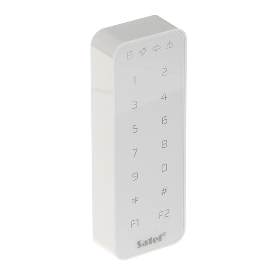
Page 7: Description
SATEL SO-MF5 2. Description LED indicators. keys for entering the code. function keys. 2.1 Function keys function key is used to directly control the keypad’s BELL output. The BELL output is a low-current OC type output. When you touch the key, the output is shorted to common ground. -
Page 8: Enclosure Opening Tool
SO-MF5 SATEL 2.3 Enclosure opening tool A tool for opening the enclosure is delivered with the keypad. Figure 4 shows how to open the enclosure using the tool. The screw must be loose. -
Page 9: Connecting The Keypad To The Computer
(e.g. ACCO-USB by SATEL). Follow the instructions in the converter manual. Do not connect more than 24 access control devices provided with the MIFARE card reader (SO-MF5, SO-MF3, CR-MF5 and CR-MF3) to the converter. The CR SOFT program may not be able to support more devices correctly. -
Page 10: Changing The Password
SO-MF5 SATEL 1. In the “New password” field, enter a password (1-16 digits, letters or special characters). 2. In the “Confirm password” field, enter the same password. 3. Click “Set”. The “SET PASSWORD” window will be closed. A message will confirm that the password has been set. -
Page 11: Changing The Program Language
SATEL SO-MF5 2. Click “CHANGE PASSWORD”. The “CHANGE PASSWORD” window will be displayed. 3. In the “Old password” field, enter the current password. 4. In the “New password” field, enter the new password (1-16 digits, letters or special characters). 5. In the “Confirm password” field, re-enter the new password. -
Page 12: Program Window
SO-MF5 SATEL 5. Click “SAVE”. The “CONFIGURATION” window will be closed. 4.2 Program window 4.2.1 Program window with the list of projects After logging in, the list of projects will be displayed in the program window. menu bar (see: “Menu bar” p. 12). -
Page 13: Program Window After Opening A Project
SATEL SO-MF5 4.2.2 Program window after opening a project tabs. title bar. menu bar (see: “Menu bar” p. 12). settings available in the tab. Tabs Click a tab to display the settings available in the tab. PROJECT – project details. -
Page 14: Title Bar
SO-MF5 SATEL Title bar The name of the open project is displayed on the title bar. 4.2.3 Menu bar Buttons and information are displayed on the menu bar. The appearance of the menu bar depends on the program window size, content displayed in the program window, etc. -
Page 15: Menu
SATEL SO-MF5 4.2.4 Menu The following commands are available in the menu: OPEN – click to close the project and return to the list of projects. SAVE – click to save changes in the project (see: “Saving changes in the project” p. 29). -
Page 16: Message Window Settings
(e.g. controller or control panel) which decides whether to grant access or not. You can select: INTEGRA/ACCO – access control devices and cards will be used in one of the SATEL systems: INTEGRA alarm system or ACCO access control system. -
Page 17: Importing A Project
SATEL SO-MF5 2. Click the type of project you want to create. The “Enter project master key (OSDP)” window will be displayed. 3. Enter the master key (32 hexadecimal characters) or click to generate a random master key. 4. Click “SET”. The “Enter project master key (OSDP)” window will be closed. -
Page 18: Deleting A Project
SO-MF5 SATEL 2. In the “Path” field, enter the file path or click to indicate the file location in the system window. 3. In the “Password” field, enter the password for the file you are importing. 4. Click “IMPORT”. The project successfully imported will be displayed on the list of projects. -
Page 19: Programming The Interface Settings
SATEL SO-MF5 If several devices have the same OSDP address, it is impossible to establish connection with the devices. If the Service mode beeps option is enabled, the devices beep when they are connected with the program. 5. Click “CONNECT”. The program will connect with the devices. If the devices are new to the project, they will be added to the project (“DEVICES”... -
Page 20: Programming The Card Settings
SO-MF5 SATEL Pulse interval (µs) – duration of a gap between two pulses. By default: 2000 µs. Supported Wiegand transmission formats 26 (ACCO-KP & INTEGRA) – even parity bit + 24 data bits + odd parity bit; byte order: from MSB to LSB. -
Page 21: Token Settings For Other On-Line System Or Standalone System
SATEL SO-MF5 SATEL token key – card number access key for all types of cards. After a project has been created, it is the same as the Master key. You can change it. The key should be unique for each project. - Page 22 SO-MF5 SATEL Sector Serial Number (SSN) – card number can be programmed and written in the selected card memory sector. MIFARE Application Directory Serial Number (MSN) – card number can be programmed and written in the card memory sector identified by the Application ID (AID).
-
Page 23: Programming The Access Control Device Settings
SATEL SO-MF5 Mode – card operating mode: Chip Serial Number (CSN) – card’s factory serial number is used as the card number. There is no need to program the cards. No additional settings are available for this mode. MIFARE Application Directory Serial Number (MSN) – card number can be programmed and written to the card. -
Page 24: Description Of The "Devices" Tab
SO-MF5 SATEL Description of the “DEVICES” tab tool bar for the list of devices. list of devices. Tool bar for the list of devices Device-related buttons and functions are displayed on the tool bar. - click to add a device to the project without connecting with the device (see: “Adding to the project a device not connected to the computer”). -
Page 25: Keypad Settings
Serial number – serial number of the device. It is read after connection is established with the device. You will find it on the label inside the device enclosure (marked as Satel MNI). Version – firmware version of the device. - Page 26 SO-MF5 SATEL After moving the card away – the card ID is sent after the card has been moved away from the reader. Signal identifier sending – way of signaling the card ID sending: According to system – the card ID sending is signaled according to the settings of the system in which the device operates (recommended for the INTEGRA system).
-
Page 27: Changing The Device's Osdp Address
SATEL SO-MF5 Standalone settings The settings are available in a Standalone system type project. Door status input – settings of the input that controls the door status (IN1): Unused – input is not used. NC – input supports a detector provided with the NC (normally closed) type output. -
Page 28: Deleting A Device From The Project
SO-MF5 SATEL Deleting a device from the project 1. Click a device on the list to select it. 2. Click . The device will be deleted. 4.3.8 Managing users This function is available after opening a Standalone system type project. You can manage the users in the “USERS”... - Page 29 SATEL SO-MF5 field – click to change the user’s code (see: “Changing the user’s code”) or delete the code (“Deleting the user’s code”). Card – if the user has no card, the button is displayed in the field – click to add a card to the user (see: “Adding a card to the user”).
- Page 30 SO-MF5 SATEL 2. In the “New code” field, enter a new code (from 4 to 12 digits). 3. In the “Confirm code” field, enter the same code. 4. Click “SET”. The “Change code” window will be closed. Deleting the user’s code 1.
-
Page 31: Deleting A User From The Project
SATEL SO-MF5 2. Click the card that you want to add to the user. 3. Click “ADD”. The “Change card” window will be closed. In the “Card” column, the number of the new card will be displayed. Deleting the user’s card 1. -
Page 32: The Int-Scr Keypad In The Integra System
SO-MF5 SATEL 2. Click “EXPORT”. The “Export project” window will be displayed. 3. In the “Password” field, enter the password to secure the file you are exporting (1-16 digits, letters or special characters). 4. Disable the Editing settings option if the system settings are to be unavailable after the file is imported (the “System”... -
Page 33: Installation In Short
− select INT-SCR as the additional interface type. − set the keypad address for the purpose of the SATEL bus. It must be a unique address in the range from 0 to 31 (different from that of the other devices connected to the same control panel bus). -
Page 34: Mounting The Keypad In The Integra System
SO-MF5 SATEL common ground CLK/D0 clock [INT-SCR interface] NC type door status input NO type request-to-exit input not used BELL OC type output 5.2.3 Mounting the keypad in the INTEGRA system 1. Place the enclosure base against the wall and mark the location of mounting holes. -
Page 35: Programming The Keypad In The Integra System
SATEL SO-MF5 11. Close the keypad enclosure. 12. Power on the keypad. 13. Start the identification function in the control panel (see the control panel installer manual). The keypad will be identified as INT-SCR. 5.2.4 Programming the keypad in the INTEGRA system You can program the keypad settings in the DLOADX program or in the LCD keypad. - Page 36 SO-MF5 SATEL Lock [Lock feature] – if the option is enabled, the keypad can control access to a single door (the following parameters are available: Lock features, Relay ON time, Max. door open time, etc.). Lock features [Lock function] – operating mode of the relay output after the access is granted: ON if partition armed [On if part.armed] –...
- Page 37 SATEL SO-MF5 Authorization control [Unauth. event] – if this option is enabled, unauthorized opening of the door will save the event to the control panel memory. Alarm on unauth. access [Unauth. alarm] – if this option is enabled, unauthorized opening of the door when the partition is armed will trigger an alarm.
- Page 38 SO-MF5 SATEL Quick arming [Quick arm] – if this option is enabled, the user needs no code / card to arm the partition using the keypad. Control “BI” output [BI outs ctrl.] – if this option is enabled, the “Bi” output operating type of users can use the keypad to control outputs.
-
Page 39: Using The Int-Scr Keypad
SATEL SO-MF5 Entry delay, part. – if you select this option, the backlight will additionally go on if entry delay countdown starts in the selected partition. Unlock door if fire no [no open] – the door will not be unlocked in the event of fire alarm. -
Page 40: Sound Signaling
SO-MF5 SATEL Flashing of the LEDs successively from right to left indicates no communication with the control panel (connection made correctly but the device has not been identified). 5.3.2 Sound signaling Beeps generated when operating The installer can disable the sound signaling or replace it with flashing of the keypad backlight. -
Page 41: [Code] / Holding The Card
SATEL SO-MF5 • toggle the state of 25. BI switch type outputs, • turn on the 24. MONO switch type outputs, • confirm the guard round, • temporarily block the partition. You can start two or more functions at the same time (e.g. disarming, alarm clearing and gaining access). -
Page 42: Generating The Alarm From The Keypad
SO-MF5 SATEL Generating the alarm from the keypad The installer can permit generating alarms from the keypad. To generate an alarm: fire alarm – touch and hold for 3 seconds, medical (auxiliary) alarm – touch and hold for 3 seconds, panic alarm –... -
Page 43: Installation In The Acco System
3.4. Program the keypad settings (p. 21): − select ACCO-SCR as the additional interface type. − set the keypad address for the purpose of the SATEL bus. The keypad with address 0 will operate as terminal A (entry terminal). The keypad with address 1 will operate as terminal B (exit terminal). -
Page 44: Description Of Terminals For Keypad In The Acco System
SO-MF5 SATEL 5. Run the cables to the place where you want to install the keypad. For the RS-485 bus, we recommend using a UTP cable (unshielded twisted pair). To make other connections, use unshielded straight-through cables. The RS-485 bus may be up to 1200 m long. -
Page 45: Connecting Using The Acco-Scr Interface
SATEL SO-MF5 3. Run wires through the opening in the enclosure base. 4. Use wall plugs and screws to secure the enclosure base to the wall. Select wall plugs specifically intended for the mounting surface (different for concrete or brick wall, different for plaster wall, etc.). -
Page 46: Using The Acco-Scr Keypad
SATEL 6.3 Using the ACCO-SCR keypad For information on how to use the keypad, please refer to the controller or the ACCO NET system manuals. Note that the LED indicators are different in the SO-MF5 keypad. 6.3.1 LED indicators Color Description ON –... -
Page 47: Description Of Terminals For Keypad In Other Manufacturer's System
SATEL SO-MF5 5. Run the cables to the place where you want to install the keypad. For the RS-485 bus, we recommend using a UTP cable (unshielded twisted pair). To make other connections, use unshielded straight-through cables. The RS-485 bus may be up to 1200 m long. -
Page 48: Standalone Door Control Module
SO-MF5 SATEL 4. Use wall plugs and screws to secure the enclosure base to the wall. Select wall plugs specifically intended for the mounting surface (different for concrete or brick wall, different for plaster wall, etc.). 5. Connect the keypad as required by the system in which the keypad is to operate. -
Page 49: Description Of Terminals For The Standalone Door Control Module
SATEL SO-MF5 8.2.2 Description of terminals for the standalone door control module Terminal Description relay output normally closed contact relay output common contact relay output normally open contact DATA/D1 not used RS-485 bus terminal [OSDP] RS-485 bus terminal [OSDP] tamper output... -
Page 50: Using The Standalone Door Control Module
SO-MF5 SATEL 6. If the keypad is to control the door status, connect the detector controlling the door status to the IN1 and COM terminals. If the keypad is not to control the door status, program the IN1 input as Not used (CR SOFT program). -
Page 51: Led Indicators
SATEL SO-MF5 8.3.2 LED indicators Color Description ON – door unblocked (permanently unlocked) blue flashing – door unlocked (user gained access) ON – alarm flashing – alarm memory green indicates no state flashing – door blocked (permanently locked) yellow 8.3.3 Sound signaling The installer can disable the sound signaling. - Page 52 2. Enter the code and touch 3. Enter the new code and touch 9. Firmware update 1. Download the device firmware update program from the support.satel.pl website. 2. Start the downloaded program. 3. Click 4. In the window that will be displayed, indicate the COM port through which communication with the device is to take place, then click “OK”.
Need help?
Do you have a question about the SO-MF5 and is the answer not in the manual?
Questions and answers