
Related Manuals for Satel INT-TSI


Summary of Contents for Satel INT-TSI
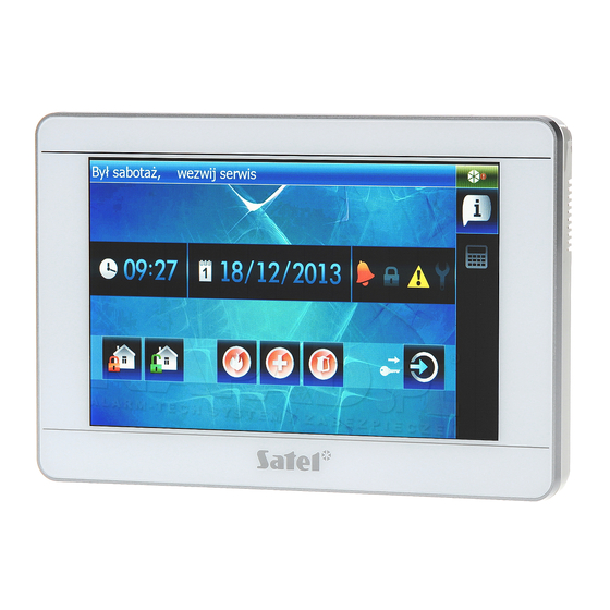
- Page 1 12/13 Keypad INT-TSI Installer Manual Firmware version 1.00 SATEL sp. z o.o. • ul. Schuberta 79 • 80-172 Gdańsk • POLAND tel. 58 320 94 00 • info@satel.pl www.satel.eu...
- Page 2 Section “Installation and hook-up” contains information on how to minimize the radio interference. The SATEL's goal is to continually upgrade the quality of its products, which may result in alterations of their technical specifications and firmware. The current information on the introduced modifications is available on our website.
-
Page 3: Specifications
The INT-TSI keypad makes possible the operation and programming of INTEGRA and INTEGRA Plus control panels with firmware version 1.12 of 2013-11-27 or newer. For programming of the keypad settings, the D X program version 1.12 or newer is required. -
Page 4: Keypad Description
INT-TSI SATEL 3. Keypad description Fig. 1. Inside of enclosure. terminals: - common ground. - power supply input. +12V - clock. - data. - zones. Z1, Z2 RSA, RSB - unused terminals – intended for future applications (RS-485). tamper switch. -
Page 5: Installation And Hook-Up
Connection to the public network may only be done through a router or xDSL modem. The INT-TSI keypad is designed for indoor installation. The place of installation should be readily accessible to the system users. 1. Open the keypad enclosure (see Fig. 2). The enclosure opening tool, shown in the illustration, is included in the keypad delivery set. - Page 6 INT-TSI SATEL Fig. 2. Opening the enclosure. 4. Install in the wall a junction box to which cables will be connected and in which a ferrite ring will be placed. The purpose of the ferrite ring delivered with the keypad is to decrease the electromagnetic interference.
- Page 7 75 – 100 m In the case of INTEGRA 24, INTEGRA 32 and INTEGRA 128-WRL control panels, the +KPD output cannot be used to power the INT-TSI keypad. You should use the OUT1 or OUT2 high-current output, programmed as type 41. P...
- Page 8 INT-TSI SATEL Fig. 5. Securing the Ethernet cable. 5. Addressing The keypad must have an individual address set in it: from the 0 to 3 range, if it is connected to the INTEGRA 24 or INTEGRA 32 control panel;...
-
Page 9: Keypad Identification
X program (”Structure” window ”Hardware” tab ”Keypads” item ”Keypads LOAD identification” button). The procedure of entering the service mode by means of the INT-TSI keypad is described in section „Programming keypad address by means of service function” (p. 6). 7. Synchronizing event memory After the keypad start-up, a window will be displayed to inform you that synchronization of the event memory is in progress. -
Page 10: Keypad Configuration
X program ("Structure" window "Hardware" tab "Keypads" item [keypad LOAD name]). The procedure of entering the service mode by means of the INT-TSI keypad is described in section „Programming keypad address by means of service function” (p. 6). Shown in square brackets are the names used in keypads. - Page 11 SATEL INT-TSI Fig. 6. "Keypad" tab in D X program. LOAD Alarms – you can define which alarms will be triggered from the keypad: – fire – using the widget or terminal (by long pressing the key for about 3 seconds).
- Page 12 INT-TSI SATEL – auxiliary [medical] – using the widget or terminal (by long pressing the key for about 3 seconds). – 3 wrong codes – entering invalid codes three times. Silent PANIC alarm [Silent panic] – with this option enabled, the panic alarm triggered from the keypad will be a silent alarm (without audible alarm signal).
- Page 13 SATEL INT-TSI backlight intensity will be reduced to approx. 15% in case of loss of AC power supply of the control panel or expander. 8.1.2 State inspections 1 – zone state [Zones] – if this option is enabled: – the user can check the state of zones on the terminal by long pressing the key with number 1 for about 3 seconds;...
- Page 14 INT-TSI SATEL 8 – chime on/off [Chime changing] – if this option is enabled, the user can switch on/off the CHIME signal in the keypad by means of the terminal, long pressing the key with number 8 for about 3 seconds.
- Page 15 SATEL INT-TSI 2EOL/NC 3EOL/NC Fig. 9. Numbering of EOL resistors (same for the NO detector). T – tamper. A – alarm. M – masking. 8.1.4 User functions definition Code+arrows – you can define which functions will be started on entering the code and touching the selected arrow key.
- Page 16 Preparing a user interface which will make it possible to optimally use the capabilities offered by the INT-TSI keypad requires an individual approach to each alarm system based on the INTEGRA / INTEGRA Plus control panel. The alarm systems differ in the way the zones and outputs are used, division into partitions, devices connected to the control panel, etc..
- Page 17 2. The "New project" window will open. In the "Categories" field, the "Base" category will be highlighted, which contains an entirely new project (available is also the "Samples" category, which contains some model projects prepared by SATEL). Click on the "Next" button to proceed to the next step.
- Page 18 INT-TSI SATEL 4. Click on the "Next" button to go to the next step. 5. Click on the "Browse" button to indicate location of the XML file with system data (see "Exporting system data by means of the DloadX program" p. 13), or click on...
- Page 19 SATEL INT-TSI 7. After the file is read in, information on the alarm system will appear at the bottom of the window. Click on the "Next" button to proceed to the next step. 8. Information on network devices, i.e. ETHM-1 modules connected to the control panel, will be displayed.
- Page 20 INT-TSI SATEL 9. Enter the network address of the ETHM-1 module. 10. Click on the "Connection test" button.
- Page 21 SATEL INT-TSI 11. A window will be displayed with information on the connection status. Click on the "OK" button to close the window. 12. Click on the button "OK" to close the "Interface" window.
- Page 22 13. Click on button "Next" to proceed to the next step. 14. A window will be displayed in which the INT-TSI keypad will be selected as the type of target device (in future, besides the INT-TSI keypad, mobile devices will be available, and selectable after clicking on ).
- Page 23 SATEL INT-TSI 15. Click on the "Next" button to proceed to the next step. 16. Click on to select a graphical interface theme.
- Page 24 INT-TSI SATEL 17. Click on the "Finish" button. A new folder will be created, to which all project files will be saved. The "New project" window will be closed. The project structure will be displayed in the "Projects" window. 8.3.2 Editing a template – first steps 1.
- Page 25 SATEL INT-TSI 2. Click on "+" next to the "Templates" to expand the list of templates. 3. Double click on the template which is to be edited (e.g. "Basic" – displayed on the keypad screen when no user is logged in).
- Page 26 INT-TSI SATEL 5. In the "Properties" window, click on the tab title to enter the text which will be displayed in the keypad (e.g. "Welcome screen"). 6. Click on the button to select the tab wallpaper. 7. Click on the wallpaper which is to be used in the tab. You can also add a new wallpaper by clicking on the "Import"...
- Page 27 SATEL INT-TSI 8. Click on the "OK" button to confirm selection of the wallpaper and close the window. 9. Click on the button to select a tab icon. 10. Click on the icon which is to be used for the tab (in the presented example, the default icon will be retained).
- Page 28 INT-TSI SATEL 11. Click on the "OK" button to confirm of the icon selection and close the window. 12. Click on the icon. 13. In the "Properties" window, advanced settings of the tab will be displayed. You can configure them so as to customize the tab to the needs of the keypad users.
- Page 29 For further information on editing templates, adding widgets, creating macro commands, etc., please refer to the TSI B program and www.satel.eu website UILDER If no terminal is placed on any of the template tabs, a tab containing the terminal will be added automatically by the keypad.
- Page 30 INT-TSI SATEL 3. In the "Output" window, information on the project compilation will be displayed. Finally, the "BUILD SUCCESSFUL" message should appear. 4. Remove the microSD card from the keypad and insert it into the memory card reader of the computer. A window will be displayed with information that a microSD card has been detected.
- Page 31 SATEL INT-TSI 5. Click on the "OK" button to assign the memory card to the project and target device. 6. The memory card information will appear on the tree representing the project structure. 7. Click on the icon to save the configuration to the memory card. The "Output" window...
-
Page 32: Slide Show
For description of how to configure these settings please refer to the user manual. 9. Slide show If a slide show is to be presented as the screen saver (see the INT-TSI keypad user manual), the pictures to be displayed must be located on the microSD card. These pictures must be placed in the "Pictures"... - Page 33 11. Click on the thumbnail to save the picture to the card or delete it from the card. 10. Updating the keypad firmware The TSI Builder program automatically downloads firmware updates for the INT-TSI keypad. The new firmware version is saved to the memory card during configuration saving (synchronization).
Need help?
Do you have a question about the INT-TSI and is the answer not in the manual?
Questions and answers