Advertisement
Quick Links
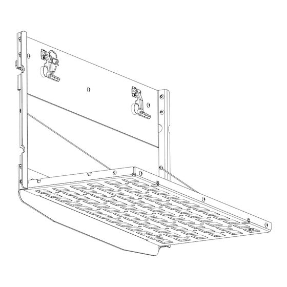
6TH GE N BRON CO
TAI LG AT E TABL E
IN S TAL L I NSTRU C TIO NS
Please read the mounting instructions below carefully before attempting to install.
Be sure to check out the install video on the product page, if available.
Thank you for purchasing from JcrOffroad! Checkout our website, www.jcroffroad.com for other great off-road
products. Be sure to rate and review our product online. If you have any questions or are missing parts, please
don't hesitate to call us at 269-353-1184!
Advertisement

Subscribe to Our Youtube Channel
Related Manuals for JCROffroad BR6


Summary of Contents for JCROffroad BR6
- Page 1 Be sure to check out the install video on the product page, if available. Thank you for purchasing from JcrOffroad! Checkout our website, www.jcroffroad.com for other great off-road products. Be sure to rate and review our product online. If you have any questions or are missing parts, please...
-
Page 2: I Nclu D E D Hardware
I NCLU D E D HARDWARE 1/4"-20 X 3/4" 10-24 X 1/2” Button Head Button Head 5-40 X 1/2” 5/16” Socket Head Nylon Plastic Washer 1/4” ID Washer 1/4"-20 X 1-1/4” Button Head 1/4” USS Flat Washer 10-24 Nylock Nut 1/4"-20 Serr. -
Page 3: Included Parts
I N CLU DE D PA RTS... - Page 4 I NS TA LL ATI ON Before starting the installation, you will need to disassemble parts of the tailgate. Start by taking off your spare tire. Then, remove both plastic vented panels on the inside of the tailgate. This can be done carefully by hand or with a plastic pry tool.
- Page 5 I NS TA LL ATI ON Next, remove your tire carrier by removing th eight bolts holding it in place using a 13mm socket. Next, using a plastic panel tool, apply firm downward pressure between the rubber seal and the tailgate panel in the three locations shown below. Do this on both the top and bottom vent pieces and remove them.
- Page 6 I NS TA LL ATI ON With the disassembly done, you can get started on the installation. Start by inserting the nut strips into the tailgate of the vehicle. The flat nut strip goes in through the hole in the bottom of the opening behind the tire carrier as shown below on the left.
- Page 7 I NS TA LL ATI ON Once both nut strips are into the tailgate, bolt them into place using four 1/4”-20 X 3/4” button head bolts with one of the larger 1/4” USS washers on each. Bolt them into the holes circled in red below. Try to center the bottom nut-strip as well as you can before tightening it into place.
-
Page 8: Installation
I NS TA L L AT I O N Next, assemble the frame as shown below using 1/4”-20 X 3/4” button head bolts, the smaller 1/4” washers and 1/4”-20 serr. flange nuts. The sides are identical, so as long as the bolt holes are facing in, it does not matter which side each goes on. - Page 9 INSTA L L AT I ON Once the frame is assembled, mount the two rubber bumpers and latches the rubber bumpers can simply be pushed into the large holes underneath the slots in the back. It works best to rotate them as you push them in. The latches get mounted to the slots above the bumpers using the 5-40 X 1/2”...
- Page 10 I NS TA LL ATI ON Next, attach the lanyards and bottom portion of the table to the sides as shown below. The lanyard is mounted to the inside of the sides using the 10-24 X 1/2” button head bolts and 10-24 nylock nuts. The table gets mounted to the bottom hole on each side using a 1/4”-20 X 3/4”...
- Page 11 I NS TA LL ATI ON Next, mount the other end of the lanyards to the inside of the table in the as shown below, using the same hardware as before. Be sure to tighten the bolts enough that the lanyards don’t wiggle but keep them loose enough that they can rotate.
- Page 12 I NS TA L L AT I O N Next, mount the assembly to the nut strips you put in the tailgate earlier as shown below. All of the holes use the 1/4”-20 X 3/4” button head bolts and small1/4” washers, except for the middle hole in the top which needs the 1/4”-20 X 1-1/4”...
- Page 13 INS TALL ATION Next, insert a 1/4”-20 X 3/4” button head bolt into each of the three holes on the front of the MOLLE panel and very loosely put a 1/4”-20 serr. flange nut on the end of each one. This just makes it easier to attach the tabletop. Finally, place the tabletop into the inside of the MOLLE panel.
- Page 14 I NS TA L L AT I O N Once the installation is complete, reinstall the exterior vents, tire carrier, wire harness, interior vent panel and spare tire in that order.
Need help?
Do you have a question about the BR6 and is the answer not in the manual?
Questions and answers