Advertisement
Quick Links
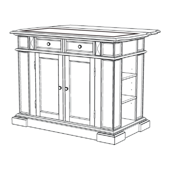
88 5004 94DLX1
Deluxe Kitchen Island
IMPORTANT NOTE
Carefully remove all the parts from the carton and put
them individually on a soft cloth to prevent scratches
or other damages occuring to the parts.
We have taken great care in the design of this
product and request that you carefully and strictly
follow our assembly instructions to ensure a
completed product as it was designed.
Part List
A.
Top Unit
1 pc.
For assembly see instructions in carton 88 5002 94DLX3
Tools required for assembly : Phillips screwdriver
Home Styles Consumer Assistance Line 888-680-7460 and 877-831-0319
servicedesk@homestyles-furniture.com
A1.
Divider
4 pcs.
Tools recommended for assembly :Level
Revised date : 20Aug2012
Advertisement

Related Manuals for Homestyles 88 5004 94DLX1


Summary of Contents for Homestyles 88 5004 94DLX1
- Page 1 88 5004 94DLX1 Deluxe Kitchen Island IMPORTANT NOTE Carefully remove all the parts from the carton and put them individually on a soft cloth to prevent scratches or other damages occuring to the parts. We have taken great care in the design of this...
- Page 2 32 pcs. (+1 extra) 4 pcs.(+1 extra) 4 pcs. For assembly see instructions in carton 88 5002 94DLX3 Tools required for assembly : Phillips screwdriver Tools recommended for assembly :Level Home Styles Consumer Assistance Line 888-680-7460 and 877-831-0319 servicedesk@homestyles-furniture.com Revised date : 20Aug2012...
- Page 3 Wood Screw for Door 17 pcs. 1 pc. Base (H) Hinge 4 pcs. 2 pcs. Back Panel (N) Tools recommended for assembly :Level Tools Required For Assembly : Phillips screwdriver Home Styles Consumer Assistance Line 888-680-7460 and 877-831-0319 servicedesk@homestyles-furniture.com Revised date : 20Aug2012...
- Page 4 Assembly Instructions 2/5 IMPORTANT * Do not tighten up all the screws until each part is properly assembled. * Y ou should keep Hex Wrench in a safe place as you may need to tighten up the Head Cap Bolts in the future. * After assembly , item must be level to work properly.
- Page 5 Assembly Instructions 3/5 Head Cap Bolt STEP 3 Attach unit from Step 2 and Middle Panel (E) to Base (H) with Head Cap Bolts. Head Cap Bolt STEP 4 Attach Leg (I) and (J) to Base (H) with Head Cap Bolts. Slide Side Panels (M) into position.
- Page 6 Assembly Instructions 4/5 STEP 5 Attach Hinge to Door (P) and (Q) with Wood Screw for Doors. (see Figure 1) Wood Screw for Door Hinge (Figure 3) (Figure 2) (Figure 1) STEP 6 Attach Rail (F) to unit with Head Cap Bolts. Head Cap Bolt Insert Adjustable Pins Into both side panels and...
- Page 7 Assembly Instructions 5/5 Wood Screw (Figure 5) (Figure 4) Pull Handle Machine Screw STEP 7 Attach Top (B) to Top Unit (A) with Wood Screws. (see Figure 4) Remove the drawers in Top Unit (A), assemble Pull Handle with Machine Screws and Dividers (A1).
Need help?
Do you have a question about the 88 5004 94DLX1 and is the answer not in the manual?
Questions and answers