Advertisement
IMPORTANT
Carefully remove all the parts from the carton and
place them individually on a soft cloth to prevent
scratches or other damage.
Carefully and strictly follow these assembly instructions
to ensure a completed product as designed.
Do not use power tools above 8 volts to assemble.
Part List
B.
C.
Side Panel
Side Panel
1 pc
.
1 pc.
I.
Back Rail
2 pcs.
N.
O.
Back Support
Back Support
1 pc.
1 pc.
Q.
Plinth
2 pcs.
Hardware List
Small Hex Wrench
1 pc.
Hex Wrench
1 pc.
Carton 5022 941 is also needed for assembly.
-
Tool(s) required for assembly: Phillips screwdriver, Level
Home Styles Customer Service: www.homestylesfurniture.com,
servicedesk@homestylesfurniture.com,
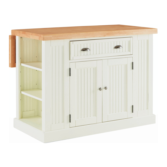
5022 942
-
Kitchen Island
D.
E.
Side Panel
Side Panel
1 pc.
1 pc.
J.
K.
Back Upright
Back Panel
1 pc.
2 pcs.
R.
P.
Leg Support
Base
1 pc.
1 pc.
M6x30
Cam Lock Screw
Head Cap Bolt
16 pcs. (+1 extra)
26 pcs. (+1 extra)
M4x16
Wood Screw
for Hinge
Cam Lock
16 pcs. (+2 extra)
27 pcs. (+2 extra)
G.
F.
Side Panel
Side Panel
1 pc.
1 pc.
L.
Shelf
4 pcs.
M.
Shelf
1 pc.
M3.5x25
Wood Screw (long)
8 pcs. (+1 extra)
M3.5x16
Wood Screw (short)
6 pcs. (+1 extra)
888-680-7460, 877-831-0319
H1.
Front Rail
1 pc.
H2.
Front Rail
1 pc.
S.
Plinth
2 pcs.
T.
Door
1 pc.
V.
Drawer
1 pc.
Refer to later page(s) of these
instructions for drawer assembly.
Adjustable Pin
20 pcs. (+1 extra)
M4x25
Machine Screw
6 pcs.
U.
Door
1 pc.
Handle
2 pcs.
Knob
2 pcs.
Advertisement
Table of Contents

Subscribe to Our Youtube Channel
Related Manuals for Homestyles 5022 942


Summary of Contents for Homestyles 5022 942
- Page 1 5022 942 Kitchen Island IMPORTANT Carefully remove all the parts from the carton and place them individually on a soft cloth to prevent scratches or other damage. Carefully and strictly follow these assembly instructions to ensure a completed product as designed.
- Page 2 Assembly Instructions 2/6 IMPORTANT Ÿ Use a soft cloth between these parts and the floor. Ÿ Do not use power tools above 8 volts to assemble. Ÿ Do not tighten all the bolts until each part is properly assembled. Ÿ The unit must be level to work properly.
- Page 3 Assembly Instructions 3/6 Cam Lock STEP 3 Attach Side Panel (E) to unit with Head Cap Bolts. Attach Back Rail (I) to unit with Cam Lock. (See Figure 3) Attach Back Upright (J) to unit. Slide Back Panels (K) into position. Head Cap Bolt Attach Back Rail (I) to unit with Cam Lock.
- Page 4 Assembly Instructions 4/6 Cam Lock STEP 5 Attach Side Panel (D) to unit with Head Cap Bolts. Attach Front Rails (H1) and (H2) to unit with Cam Locks. Attach Side Panel (F) to unit with Head Cap Bolts and Cam Locks. Head Cap Bolt STEP 6 Turn unit to its upright position.
- Page 5 Assembly Instructions 5/6 Drawer (V) Wood Screw (long) Bottom STEP 7 Attach Drawer Front (V1) and Drawer Back (V2) to Drawer Side (V3) with Wood Screws (long). Attach Drawer Side (V4) to unit Roller at back with Wood Screws (long). STEP 8 Wood Screw (short) Slide Drawer Bottom (V5) into groove.
- Page 6 Assembly Instructions 6/6 Cam Lock Screw Wood Screws for Hinge STEP 10 Place Tops (A1) and (A2) upside down on a soft cloth. Attach Top (A2) to Top (A1) with Wood Screws for Hinge. Insert Cam Lock Screws into pre-drilled holes of top unit, then tighten.
- Page 7 CARE INSTRUCTIONS NEVER NEVER use glass cleaners on allow liquids to remain on furniture. finished furniture. Ammonia Absorption causes parts to warp chemically attacks the finish. and split and finishes to delaminate. Do not use power tools Do not place Do not write above 8 volts to assemble.
Need help?
Do you have a question about the 5022 942 and is the answer not in the manual?
Questions and answers