Advertisement
Quick Links
IMPORTANT
Carefully remove all the parts from the carton and
place them individually on a soft cloth to prevent
scratches or other damage.
Carefully and strictly follow these assembly instructions
to ensure a completed product as designed.
Do not use power tools above 8 volts to assemble.
Part List
Hardware List
Hex Wrench
1 pc.
Small Hex Wrench
1 pc.
For assembly see instructions in carton 5094 942.
home
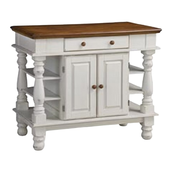
5094 941
-
Kitchen Island
M6x35
Cam Lock Screw
Head Cap Bolt
4 pcs. (+1 extra)
16 pcs. (+1 extra)
M6x50
Cam Lock
Head Cap Bolt (long)
4 pcs. (+2 extra)
4 pcs. (+1 extra)
styles Customer Service: www.homestylesfurniture.com,
servicedesk@homestylesfurniture.com,
A.
Top
1 pc.
F.
Foot
4 pcs.
Flat Washer
4 pcs. (+1 extra)
Spring Washer
4 pcs. (+1 extra)
-
888-680-7460
Adjustable Pin
4 pcs. (+1 extra)
M4x20
Knob
Machine Screw
8 pcs.
8 pcs.
Advertisement

Related Manuals for Homestyles 5094 941


Summary of Contents for Homestyles 5094 941
- Page 1 5094 941 Kitchen Island IMPORTANT Carefully remove all the parts from the carton and place them individually on a soft cloth to prevent scratches or other damage. Carefully and strictly follow these assembly instructions to ensure a completed product as designed.
- Page 2 Shelf Door Door Shelf 2 pcs. 2 pcs. 2 pcs. 1 pc. Base Stretcher 2 pcs. 1 pc. Carton 5094 941 is also needed for assembly. Tool(s) required for assembly: Phillips screwdriver, Level home styles Customer Service: www.homestylesfurniture.com, servicedesk@homestylesfurniture.com, 888-680-7460...
- Page 3 Assembly Instructions 2/6 IMPORTANT Ÿ Use a soft cloth between these parts and the floor. Ÿ Do not use power tools above 8 volts to assemble. Ÿ Do not tighten all the bolts until each part is properly assembled. Ÿ The unit must be level to work properly.
- Page 4 Assembly Instructions 3/6 STEP 3 Attach Side Panels (C) to Rails (B) with Cam Lock Cam Locks. (See Figure 2) Figure 2 STEP 4 Place Top (A) upside down on a soft cloth. Attach unit to Top (A).
- Page 5 Assembly Instructions / 4 6 STEP 5 Head Cap Bolt Attach Stretchers (L) to Posts (D) and (E) with Head Cap Bolts. (See Figure 3) Figure 3 Head Cap Bolt STEP 6 Attach Shelves (G1) and (G2) to unit from Step 4. Attach units from Step 5 to unit with Head Cap Bolts.
- Page 6 Assembly Instructions / 5 6 Head Cap Bolt STEP 7 Attach Base (K) to unit with Head Cap Bolts. Flat Washer Spring Washer Head Cap Bolt (long) STEP 8 Attach Feet (F) to unit with Flat Washers, Spring Washers and Head Cap Bolts (long). (See Figure 4) Figure 4...
- Page 7 Assembly Instructions 6/6 Knob Machine Screw Adjustable Pin STEP 9 Turn unit over to its upright position. Insert Adjustable Pins into side panels at desired level. Place Shelf (J) into position. Attach Doors (H) and (I) to unit by sliding door hinges into side panel hinges. (See Figure 5) Attach Knobs to Doors (H) and (I) with Machine Screws.
- Page 8 CARE INSTRUCTIONS NEVER NEVER use glass cleaners on allow liquids to remain on furniture. finished furniture. Ammonia Absorption causes parts to warp chemically attacks the finish. and split and finishes to delaminate. Do not use power tools Do not place Do not write above 8 volts to assemble.
Need help?
Do you have a question about the 5094 941 and is the answer not in the manual?
Questions and answers