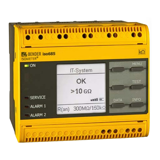
Bender ISOMETER isoHR685W I-B Series Quick Start Manual
Insulation monitoring device
Hide thumbs
Also See for ISOMETER isoHR685W I-B Series:
- Quick start manual (8 pages) ,
- Manual (70 pages)
Summary of Contents for Bender ISOMETER isoHR685W I-B Series
- Page 1 Kurzanleitung DE Quick-start guide EN ISOMETER® isoHR685W-x-I-B Isolationsüberwachungsgerät Insulation monitoring device isoHR685W-x-I-B_D00261_06_Q_DEEN/03.2024...
- Page 2 ISOMETER® isoHR685W-x-I-B ISOMETER® isoHR685W-x-I-B ISOMETER® isoHR685W-x-I-B Isolationsüberwachungsgerät Insulation monitoring device Diese Kurzanleitung ersetzt nicht das Handbuch! This quick-start guide does not replace the manual! Kurzanleitung für folgende Geräte Quick-start guide for the following devices Typ / Type Versorgungsspannung U / Supply voltage U Art.-Nr.
-
Page 3: Safety Instructions
ISOMETER® isoHR685W-x-I-B Safety instructions Sicherheitshinweise ! Elektrischer Schlag! An den Klemmen ! Electric shock! The terminals carry high efahr anger liegt eine hohe Spannung an, die bei direkter voltage and direct contact with these terminals Berührung lebensgefährlich ist. Nehmen Sie das will likely result in electrocution. -
Page 4: Montage
ISOMETER® isoHR685W-x-I-B Montage Mounting Ø M4 Montage auf Hutschiene / DIN rail mounting Schraubbefestigung /Screw mounting Anschluss Connection Verdrahten Sie das Gerät gemäß Anschlussplan. Beach- Wire up the device according to the wiring diagram ta- ten Sie dabei die technischen Daten. Montieren Sie nach king account of the technical data. -
Page 5: Wiring Diagram
ISOMETER® isoHR685W-x-I-B L1/+ L3/- Anschlussbild Wiring diagram 3(N)AC A1/+ A2/- L1/+ L3/- A1/+ A2/- L1/+ L3/- KE E L1/+ L3/- IT system 1 IT system 2 A1/+ A2/- L1/+ L3/- A1/+ A2/- L1/+ L3/- KE E L1/+ L3/- IT system 11 12 14 21 22 24 Example... - Page 6 ISOMETER® isoHR685W-x-I-B Legende zu den Anschlussbildern Legend to the wiring diagrams Anschlüsse Klemme/Terminal Connections Stromversorgung, Power supply, A1/+ A2/- ** = 24…240V (50…400Hz) = 24…240V (50…400 Hz) Anschlüsse an das zu überwachende Netz Connections to the system to be monitored AC 0…1000 V, 3AC 0…690 V AC 0…1000 V, 3AC 0…690 V L1/+, L2, L3/-...
- Page 7 ISOMETER® isoHR685W-x-I-B ISOsync: Überwachung langer paralleler Kabel ISOsync: Monitoring of long parallel cables In kapazitiv gekoppelten IT-Systemen kann es zu gegen- ISOMETER®s can interfere with each other when used in seitiger Beeinflussung der ISOMETER® kommen. capacitively coupled IT-systems. A1/+ A2/- L1/+ L3/- A1/+...
-
Page 8: Inbetriebnahme Des Geräts
ISOMETER® isoHR685W-x-I-B Inbetriebnahme des Geräts Commissioning of the device 1. Prüfen auf korrekten Anschluss des ISOMETER®s an 1. Check that the ISOMETER® is properly connected to das zuüberwachende Netz. the system to be monitored. 2. Versorgungsspannung für ISOMETER® zuschalten 2. Connect the supply voltage to the ISOMETER® 3. - Page 9 ISOMETER® isoHR685W-x-I-B Schritte zur Inbetriebnahme Steps for Commision Select Select Select Response value Response value Language Date and time System type profile for Alarm 1 for Alarm 2 Power circuit Deutsch 40 kΩ...
-
Page 10: Factory Settings
ISOMETER® isoHR685W-x-I-B Werkseinstellungen Factory settings Ansprechwerte Response values Ansprechwert R (Alarm 1) ..............100 kΩ Response value R (Alarm 1) ..............100 kΩ Ansprechwert R (Alarm 2) ..............20 kΩ Response value R (Alarm 2) ..............20 kΩ Fehlerspeicher....................aus Fault memory .....................off Ankoppelüberwachung ................ein Coupling monitoring ...................on Geräteprofil ................„Leistungskreise“... -
Page 11: Technische Daten
ISOMETER® isoHR685W-x-I-B Technische Daten Technical data Isolationskoordination (IEC 60664-1/IEC 60664-3) Insulation co-ordination (IEC 60664-1/IEC 60664-3) Bemessungsisolationsspannung (IEC 60664-1) ........1000 V Rated insulation voltage (IEC 60664-1) ..........1000 V Bemessungs-Stoßspannung (IEC 60664-1) ..........8 kV Rated impulse voltage (IEC 60664-1) ............8 kV Überspannungskategorie (OVC) ............III, 1000V Overvoltage category (OVC) ............ -
Page 12: Eu-Konformitätserklärung
Alle Rechte vorbehalten. 35305 Grünberg Nachdruck und Vervielfältigung nur mit Germany Genehmigung des Herausgebers. © Bender GmbH & Co. KG, Germany Subject to change! The specified Tel.: +49 6401 807-0 All rights reserved. standards take into account the edition info@bender.de...


Need help?
Do you have a question about the ISOMETER isoHR685W I-B Series and is the answer not in the manual?
Questions and answers