Bender ISOMETER isoHV425 Manual
Insulation monitoring device with coupling device
Hide thumbs
Also See for ISOMETER isoHV425:
- Manual (54 pages) ,
- Operating manual (33 pages) ,
- Quick start manual (12 pages)
Table of Contents
Advertisement
Quick Links
Advertisement
Table of Contents

Subscribe to Our Youtube Channel
Related Manuals for Bender ISOMETER isoHV425


Summary of Contents for Bender ISOMETER isoHV425
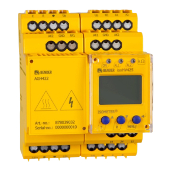
- Page 1 Manual EN ISOMETER® isoHV425 with AGH422 Insulation monitoring device with coupling device for unearthed AC, AC/DC and DC systems up to 3(N)AC, AC 1000 V Software version: D0453 V1.xx (isoHV425-D4-4) / D0500 V1.xx (isoHV425-D4M-4) isoHV425_D00082_06_M_XXEN/07.2023...
- Page 2 isoHV425_D00082_06_M_XXEN/07.2023...
-
Page 3: Table Of Contents
Indication of important instructions and information...............5 Signs and symbols............................5 Service and Support............................5 Training courses and seminars........................5 Delivery conditions............................6 Inspection, transport and storage......................6 Warranty and liability.............................6 Disposal of Bender devices..........................6 1.10 Safety..................................7 Function.......................8 Intended use..............................8 Device features..............................8 Functional description........................... 9 2.3.1... - Page 4 Table of contents Menu overview...............................22 Displaying measured values........................22 Setting the response values (AL)......................23 4.4.1 Setting the response values for insulation monitoring..............23 4.4.2 Setting the response values for undervoltage and overvoltage..........24 4.4.3 Response values overview.........................24 Configuring fault memory, alarm relays, and interfaces (out)............24 4.5.1 Configuring the relays..........................24 4.5.2...
-
Page 5: General Information
Recycling RoHS directives Service and Support Information and contact details about customer service, repair service or field service for Bender devices are available on the following website: Fast assistance | Bender GmbH & Co. KG. Training courses and seminars Regular face-to-face or online seminars for customers and other interested parties: www.bender.de >... -
Page 6: Delivery Conditions
General information Delivery conditions The conditions of sale and delivery set out by Bender GmbH & Co. KG apply. These can be obtained in printed or electronic format. The following applies to software products: ‘Software clause in respect of the licensing of standard software as part of deliveries,... -
Page 7: Safety
ISOMETER® isoHV425 with AGH422 1.10 Safety If the device is used outside the Federal Republic of Germany, the applicable local standards and regulations must be complied with. In Europe, the European standard EN 50110 applies. DANGER Risk of fatal injury due to electric shock! Touching live parts of the system carries the risk of: •... -
Page 8: Function
• Two separately adjustable response value ranges from 10…500 k • isoHV425-D4-4: RS-485 (galvanically isolated) including the following protocols: – BMS (Bender measuring device interface) for the data exchange with other Bender devices – Modbus RTU – IsoData (for continuous data output) •... -
Page 9: Functional Description
ISOMETER® isoHV425 with AGH422 Functional description The ISOMETER® measures the insulation resistance R and the system leakage capacitance C between the system to be monitored (L1/+, L2/–) and earth (PE). The RMS value of the system voltage U between L1/+ and L2/–, as well as the DC residual voltages U (between L1/+ and earth) and U (between L2/–... -
Page 10: Undervoltage/Overvoltage Monitoring
Function 2.3.2 Undervoltage/overvoltage monitoring , the two parameters 'U ˂' and 'U ˃' can be enabled in the response- To monitor the nominal system voltage U value menu 'AL' (chapter 4.4). The maximum undervoltage value is limited by the overvoltage value. The RMS value of the nominal system voltage U is monitored. - Page 11 ISOMETER® isoHV425 with AGH422 Error codes In the event of a device error, error codes are shown in the display. Some of these are described below: Overview of some error codes Error code Meaning PE connection error The connection of 'E' or 'KE' to earth is interrupted. E.01 Action: Check connection, eliminate error.
-
Page 12: Alarm Assignment Of The Alarm Relays K1/K2
Function User-controlled test functions The user-controlled test functions interrupt the measuring function of the device. They always include a test of the measurement technology (error code 'E.05') and additionally a test of the connection between the terminals L1/+ and L2/– via the system to be monitored (error code 'E.02') which can be activated by the user (menu 'SEt' / 'nEt'). -
Page 13: Password Protection (On, Off)
ISOMETER® isoHV425 with AGH422 Delay on release t The delay on release t can be set uniformly for all alarm messages using the parameter 'toff', while each alarm message specified in the alarm assignment has its own timer for t An alarm message will be signalled until the limit value of the respective measured value is no longer violated (including hysteresis) for the duration of t without interruption. -
Page 14: Digital Interfaces (Isohv425-D4-4)
The ISOMETER® uses the serial hardware interface RS-485 with the following protocols: • BMS The BMS protocol is an essential component of the Bender measuring device interface (BMS bus protocol). Data transmission generally makes use of ASCII characters. • Modbus RTU Modbus RTU is an application layer messaging protocol, and it provides master/slave communication between devices that are connected via bus systems and networks. -
Page 15: Installation, Connection And Commissioning
ISOMETER® isoHV425 with AGH422 Installation, connection and commissioning Dimensions 45 70.5 31.1 47.5 74.5 Figure: Dimension diagram (in mm) Installation Application in rail vehicles/DIN EN 45545-2:2016 If the distance to neighbouring components that do not comply with the requirement of DIN EN 45545-2 table 2 is <20 mm horizontally or <200 mm vertically, these components shall be considered grouped. -
Page 16: Connection
Installation, connection and commissioning Connection CAUTION Danger from touching hot surfaces! If the AGH is operated at mains voltages > 800 V, the temperature of the enclosure may exceed 60 °C. • Do not touch the surfaces of the device after connecting it to the mains voltage. For details about the required conductor cross sections, refer to chapter 'Technical data'. - Page 17 ISOMETER® isoHV425 with AGH422 Wiring diagram for isoHV425(W)-D4-4 Figure: Wiring diagram with RS-485 interface isoHV425_D00082_06_M_XXEN/07.2023...
- Page 18 Installation, connection and commissioning Anschlusszeichnung for isoHV425(W)-D4M-4 Figure: Wiring diagram with analogue interface isoHV425_D00082_06_M_XXEN/07.2023...
-
Page 19: Commissioning
ISOMETER® isoHV425 with AGH422 Commissioning Check that the ISOMETER® is properly connected to the system to be monitored. Connect supply voltage U to the ISOMETER®. The device carries out a calibration, a self test and adjusts itself to the IT system to be monitored. With high system leakage capacitances this process may take up to 4 min. -
Page 20: Operation
Operation Operation Operating and display elements Device front Operating elements Function Device is running Prewarning Overvoltage Alarm Undervoltage Up and down buttons – For navigating up or down in the menu settings. – For increasing or decreasing values. Test button (press > 1.5 s) Reset button (press >... - Page 21 ISOMETER® isoHV425 with AGH422 Display Display elements Function Nominal system voltage U Insulation resistance R System leakage capacitance C Monitored conductors L1 L2 Voltage type DC Pulse symbol: error-free measured value update Voltage type AC °C Measured values and units μ...
-
Page 22: Menu Overview
Operation Menu overview Measurement display Menu selection Parameter selection Menu item Parameter Querying and setting response values Configuring fault memory, alarm relays and interface Setting delay times and self test cycles Setting device control parameters Querying software version Querying and clearing the history memory Going to the next-higher menu level Displaying measured values Overview... -
Page 23: Setting The Response Values (Al)
ISOMETER® isoHV425 with AGH422 Display Description ✓ Nominal system voltage L1 - L2 ~ ± U L1 L2 V …1.15 kV Resolution: 1 V Residual voltage L1/+ - PE ✓ ± U L1 DC 0 ±1.15 kV Resolution: 1 V Residual voltage L2/–... -
Page 24: Setting The Response Values For Undervoltage And Overvoltage
Operation 4.4.2 Setting the response values for undervoltage and overvoltage How to proceed Open menu 'AL'. Select parameter 'U <' for undervoltage or parameter 'U >' for overvoltage. Set value and confirm with Enter. 4.4.3 Response values overview Display Activation Setting value Description Range... -
Page 25: Activating Or Deactivating Fault Memory
ISOMETER® isoHV425 with AGH422 K1 'r1' K2 'r2' LEDs Description Display Display Device error E.xx 1 Err 2 Err Prewarning R1 +R1 < +R1 < Fault R at L1/+ Prewarning R1 –R1 < –R1 < Fault R at L2/– Alarm R2 +R2 <... -
Page 26: Configuring Interface (Isohv425-D4-4)
Operation 4.5.4 Configuring interface (isoHV425-D4-4) Display Setting value Description Range Adr = 0 deactivates BMS as well as Modbus 0/3…90 Bus Adr. and activates isoData with continuous data output (115k2, 8E1) ---/ '---': BMS bus (9k6, 7E1) Adr 1 '---' ) Baud rate 1.2k…115k '1.2k' …... -
Page 27: Setting Device Control Parameters (Set)
System connection test S.Ct Device test at device start Restore factory settings For Bender Service only FAC Factory settings Customer settings Reset to factory settings All settings with the exception of the interface parameters are reset to the factory settings. -
Page 28: Querying Software Version (Inf)
Operation Delete history memory Call up 'HiS' menu, go to 'Clr' and confirm. 4.10 Querying software version (InF) The software version is displayed as a ticker. Afterwards it can be output step by step using the up or down buttons. How to proceed Press MENU button (>... -
Page 29: Data Access Via Rs-485 Interface
ISOMETER® isoHV425 with AGH422 Data access via RS-485 interface Data access using the BMS protocol The BMS protocol is an essential component of the Bender measuring device interface (BMS bus protocol). Data transmission generally makes use of ASCII characters. BMS channel no. -
Page 30: Writing The Modbus Register (Parameter Setting)
Data access via RS-485 interface Command of the master to the ISOMETER® In the following example, the master of the ISOMETER® requests the content of register 1003 using address 3. The register contains the channel description of measuring channel 1. Byte Name Example... -
Page 31: Exception Code
ISOMETER® isoHV425 with AGH422 Response of the ISOMETER® to the master Byte Name Example Byte 0 ISOMETER® Modbus address 0x03 Byte 1 Function code 0x10 Byte 2, 3 Start register 0x0BBB Byte 4, 5 Number of registers 0x0001 Byte 6, 7 CRC16 checksum 0x722A 5.2.3... -
Page 32: Modbus Register Assignment
Data access via RS-485 interface Modbus register assignment 5.3.1 Modbus measured value registers Depending on the device condition, the information in the registers is the measured value without alarm, the measured value with alarm 1, the measured value with alarm 2, or the device error. For more information see , page 33. - Page 33 ISOMETER® isoHV425 with AGH422 5.3.1.2 Float = Floating point value of the channels Representation of the bit order for processing analogue measured values according to IEEE 754 Word 0x00 0x01 Byte HiByte LoByte HiByte LoByte 31 30 29 28 27 26 25 24 23 22 21 20 19 18 17 16 15 14 13 12 11 10 exponent mantissa sign...
- Page 34 Data access via RS-485 interface 5.3.1.4 R&U = Range and unit Meaning Unit Invalid (init) No unit Baud °C °F Second Minute Hour Month Range of validity Actual value The actual value is lower The actual value is higher Invalid value •...
-
Page 35: Modbus Parameter Register
ISOMETER® isoHV425 with AGH422 5.3.1.5 Channel descriptions Value Description of measured value / message Comments 1 (0x01) Insulation fault 71 (0x47) Insulation fault Insulation resistance R 76 (0x4C) Voltage Measured value in V 77 (0x4D) Undervoltage 78 (0x4E) Overvoltage 82 (0x52) Capacitance Measured value in F 86 (0x56) - Page 36 Data access via RS-485 interface Register Property Description Format Unit Value range Activation alarm value overvoltage 'U >' 0 = off 3010 UINT 16 1 = on 3011 Alarm value overvoltage 'U >' UINT 16 U < … 1100 Memory function for alarm 0 = off 3012 UINT 16...
- Page 37 ISOMETER® isoHV425 with AGH422 Register Property Description Format Unit Value range 3027 Alarm assignment of relay 1 'r1' UINT 16 Bit 9 … Bit 1 3028 Alarm assignment of relay 2 'r2' UINT 16 Bit 9 … Bit 1 8003 Factory settings for all parameters UINT 16 0x6661 'fa'...
- Page 38 Data access via RS-485 interface Display indication Meaning rx test Manually started self test rx S.AL Device start with alarm When reading: 0; Reserved When writing: any value When reading: 0 Reserved When writing: any value When reading: 0; 12…15 Reserved When writing: any value 5.3.2.3...
-
Page 39: Isodata Data String
ISOMETER® isoHV425 with AGH422 IsoData data string In IsoData mode the ISOMETER® sends the entire data string roughly once per second. Communication with the ISOMETER® in this mode is not possible and no additional sender may be connected via the RS-485 bus cable. -
Page 40: Technical Data
Technical data Technical data Technical data isoHV425 ( )* = factory setting Insulation coordination acc. to IEC 60664-1/-3 Definitions Supply circuit (IC2) A1, A2 Output circuit (IC3) 11, 14, 24 Control circuit (IC4) Up, KE, T/R, A, B, AK1, GND, AK2; M+, M– Rated voltage 240 V Overvoltage category... - Page 41 ISOMETER® isoHV425 with AGH422 IT system being monitored Nominal system voltage U with AGH422 AC 0…1000 V / DC 0…1000 V Tolerance of U AC +10 %, DC +10 % Nominal system voltage range U with AGH422 (UL508) AC/DC 0…600 V Frequency range of U DC, 15…460 Hz Measuring circuit...
- Page 42 Technical data Operating uncertainty ±5 %, at least ±5 V Display range measured value system leakage capacitance at R > 20 k 0…200 F Operating uncertainty ±15 %, at least ±2 F Password off / 0…999 (0, off)* Fault memory alarm messages on/(off)* Interface (isoHV425-D4-4 only) Interface / protocol...
- Page 43 ISOMETER® isoHV425 with AGH422 Contact data acc. to IEC 60947-5-1 Utilisation category AC-12 / AC-14 / DC-12 / DC-12 / DC-12 Rated operational voltage 230 V / 230 V / 24 V / 110 V / 220 V Rated operational current 5 A / 2 A / 1 A / 0.2 A / 0.1 A Minimum contact rating 1 mA at AC/DC ≥...
-
Page 44: Technical Data Agh422
Technical data Weight ≤ 150 g Technical data AGH422 Insulation coordination acc. to IEC 60664-1/-3 Definitions Measuring circuit (IC1) L1/+, L2/– Control circuit (IC2) AK1, GND, AK2, Up, E Rated voltage 1000 V Overvoltage category Rated impulse voltage IC1/IC2 8 kV Rated insulated voltage IC1/IC2 1000 V... - Page 45 ISOMETER® isoHV425 with AGH422 Environment/EMC IEC 61326-2-4; DIN EN 50121-3-2 Ambient temperatures Operation U < 700 V –40…+70 °C Operation U > 700 V –40…+55 ºC Transport –40…+85 °C Storage –40…+70 °C Classification of climatic conditions acc. to IEC 60721 (related to temperature and rel.humidity) Stationary use (IEC 60721-3-3) 3K22 •...
-
Page 46: Connection (For Isometer® And Agh)
Technical data Connection (for ISOMETER® and AGH) Screw-type terminals Nominal current ≤ 10 A Tightening torque 0.5…0.6 Nm (5…7 lb-in) Conductor sizes AWG 24…12 Stripping length 8 mm Rigid/flexible 0.2…2.5 mm Flexible with ferrules with/without plastic sleeve 0.25…2.5 mm Multi-conductor rigid 0.2…1.5 mm Multi-conductor flexible 0.2…1.5 mm... -
Page 47: Ordering Data
ISOMETER® isoHV425 with AGH422 EU Declaration of Conformity Hereby, Bender GmbH & Co. KG declares that the device covered by the Radio Directive complies with Directive 2014/53/EU. The full text of the EU Declaration of Conformity is available at the following Internet address: https://www.bender.de/fileadmin/content/Products/CE/CEKO_isoXX425.pdf... -
Page 48: Change Log
Technical data Change log Date Document Software State/Changes version 09.2021 Editorial revision p. 21 Information rail vehicles p. 51 Standards, Change log 02.2022 p. 51 Ordering information, Change log 07.2023 Editorial revision • Transfer to editorial system incl. new CI •... - Page 49 Alle Rechte vorbehalten. 35305 Grünberg Nachdruck und Vervielfältigung nur mit Germany Genehmigung des Herausgebers. © Bender GmbH & Co. KG, Germany Subject to change! The specified Tel.: +49 6401 807-0 All rights reserved. standards take into account the edition info@bender.de Reprinting and duplicating only with valid until 07.2023 unless otherwise...
Need help?
Do you have a question about the ISOMETER isoHV425 and is the answer not in the manual?
Questions and answers