Bender ISOMETER isoHV425 AGH422 Series Quick Start Manual
Hide thumbs
Also See for ISOMETER isoHV425 AGH422 Series:
- Manual (54 pages) ,
- Operating manual (33 pages) ,
- Quick start manual (12 pages)
Table of Contents

Related Manuals for Bender ISOMETER isoHV425 AGH422 Series


Summary of Contents for Bender ISOMETER isoHV425 AGH422 Series
- Page 1 ISOMETER® isoHV425xx & AGH422 Isolasjonsovervåkingsrele for isolerte AC-, AC/DC- og DC-Nett (IT-System) for spenninger inntil 3(N)AC, AC 1000 V, DC 1000 V Oppstartguide / Quick-start guide NO/EN isoHV425_D00082_04_Q_NOEN/ 07.2021...
-
Page 2: Ordering Information
Part of the device documentation in addition to hurtigveilederen er de vedlagte "Sikkerhets- this quickstart is the enclosed “Safety instructions instruksjoner for Bender-produkter" og manualen, for Bender products“ and the manual, which can som kan lastes ned fra https://www.bender.de/en/ be downloaded from https://www.bender.de/en/ service-support/downloads. - Page 3 ISOMETER® isoHV425xx & AGH422 Dimensjoner Dimensions 36 mm Montering Mounting Fare for elektrisk støt! Unngå all fysisk of electric shock! Avoid any physical con- kontakt mellom aktive ledere og vær i samsvar tact with active conductors and ensure compli- med forskrifter for arbeid på elektriske ance with the regulations for working on elect- installasjoner.
- Page 4 ISOMETER® isoHV425xx & AGH422 Kobling Wiring Koblingsskjema isoHV425-D4-4 Wiring diagramm isoHV425-D4-4 L1/+ L2/- Test / Reset GND AK2 MENU COM465IP L1/+ L2/- RS-485 Legende Tilkoblinger Klemme/ Connections Terminal Tilkobling til nettspenning U via en sikring: A1, A2 Connection to the supply voltage U via a fuse: Om forsynt via et IT-system må...
- Page 5 ISOMETER® isoHV425xx & AGH422 Koblingsskjema isoHV425-D4M-4 Wiring diagramm isoHV425-D4M-4 L1/+ L2/- Test / Reset GND AK2 MENU L1/+ L2/- Tilkobling Klemme/ Connections Terminal Tilkobling av alarmrelé „K1“ 11, 14 Connection to alarm relay „K1“ Tilkobling av alarmrelé „K2“ 11, 24 Connection to alarm relay „K2“...
-
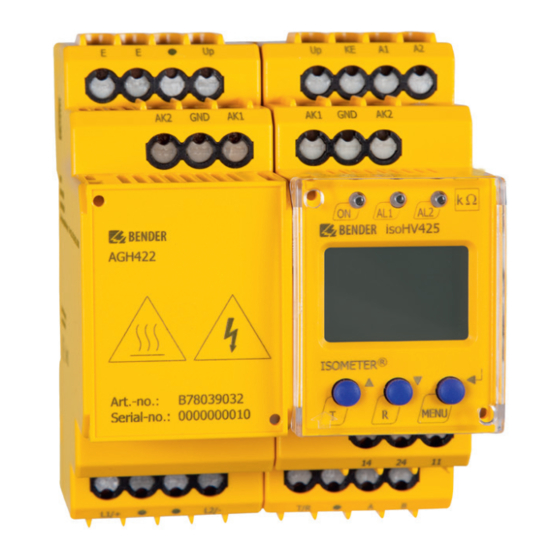
Page 6: Display Elements
ISOMETER® isoHV425xx & AGH422 Displayelementer Display elements Enhetens forside/ Device front Funksjon Function grønn - På green - On gul - Alarm yellow - Alarm gul - Alarm yellow - Alarm Pil opp - tast Up button Testknapp (hold inne i > 1,5 s) Test button (press >... -
Page 7: Menu Overview
ISOMETER® isoHV425xx & AGH422 Menyoversikt Menu overview Måledisplay Menyvalg Parametervalg Measurement display Menu selection Parameter selection > < 1.5 s > > . . . 1.5 s 1.5 s < t > 5 Min. < > 1.5 s R [k ] C [µF] U L1 L2 [V ] UL1 [V ]... - Page 8 ISOMETER® isoHV425xx & AGH422 Idriftsetting Commissioning Sjekk at ISOMETER® er skikkelig koblet til systemet Check that the ISOMETER® is properly connected to som skal overvåkes. the system to be monitored. Koble til forsyningsspenning U på ISOMETER®. Connect the supply voltage U to the ISOMETER®.
-
Page 9: Tekniske Data
ISOMETER® isoHV425xx & AGH422 Tekniske data Technical data ()* = Fabrikkinnstillinger ()* = Factory settings Isolasjonskoordinasjon ihht. IEC 60664-1/ IEC Insulation coordination acc. to IEC 60664-1/ 60664-3 IEC 60664-3 Oppgitt spenning ............240 V Rated voltage ................240 V Overspenningskategori .............. III Overvoltage category .............. - Page 10 ISOMETER® isoHV425xx & AGH422 Enhetsadresse, BMS-Bus, Modbus RTU ......3…90 (3)* Device address, BMS bus, Modbus RTU ......3…90 (3)* Tilkobling Connection Tilkoblingstype............... Fjærklemme Connection type ......screw-type or push-wire terminal Nominell strøm ...............≤ 10 A Nominal current ..............≤ 10 A Tverrsnitt ..............AWG 24-14 Cross section ..............AWG 24-14 Avisoleringslengde ..............10 mm...
- Page 11 ISOMETER® isoHV425xx & AGH422 Innstillinger for terminaler Up, AK1, GND, AK2: Single cables for terminals Up, AK1, GND, AK2: Ledningens lengde ..............≤ 0,5 m Cable lengths ................≤ 0.5 m Tverrsnitt ................≥ 0,75 mm Cross section..............≥ 0.75 mm Annet Other Driftsmodus .............
- Page 12 Nachdruck und Vervielfältigung Reprinting and duplicating nur mit Genehmigung des Herausgebers. only with permission of the publisher. Bender GmbH & Co. KG Bender GmbH & Co. KG Postfach 1161 • 35301 Grünberg • Deutschland PO Box 1161 • 35301 Grünberg • Germany Londorfer Str.
Need help?
Do you have a question about the ISOMETER isoHV425 AGH422 Series and is the answer not in the manual?
Questions and answers