
Related Manuals for Bender ISOMETER isoHR1685DW-925


Summary of Contents for Bender ISOMETER isoHR1685DW-925
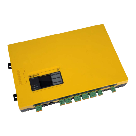
- Page 1 Manual ISOMETER® isoHR1685DW–925 Insulation monitoring device for isolated mobile elevating working platforms Software version isoHR1685DW-925: D0601 V2.2x, D0602 V1.0x isoHR1685DW-925_D00369_01_M_XXEN/02.2021...
- Page 2 E-Mail: info@bender.de Web: www.bender.de Customer service Service-Hotline: 0700-BenderHelp (Telefon und Fax) Carl-Benz-Straße 8 • 35305 Grünberg • Germany © Bender GmbH & Co. KG Tel.:+49 6401 807-760 All rights reserved. Fax:+49 6401 807-629 Reproduction only with permission of the publisher.
-
Page 3: Table Of Contents
Table of content 1. Important information ................5 5. Installation and connection ..............15 1.1 How to use this manual ..........5 5.1 Installation . - Page 4 Table of content 8.2 (1.6) Outputs ..........25 10.
-
Page 5: Important Information
1.2 Technical support 1.2.1 End customer support and advice This manual is intended for qualified personnel working in electrical Technical support by phone or e-mail for all Bender products engineering and electronics! • Questions concerning specific customer applications • Commissioning Read the manual before you begin to mount, connect, and commission •... -
Page 6: Training Courses
Products and Services of the Electrical and Electronics Industry” (GL)* Sale and delivery conditions can be obtained from Bender in printed or electronic format. • Old electrical and electronic equipment from users other than private households which was introduced to the market after 13 August 2005 must be taken back by the 1.5 Storage... -
Page 7: Safety Instructions
Make sure that the basic settings meet the requirements of the IT system. Part of the device documentation in addition to this manual is the enclosed "Safety in- Persons without the necessary expertise, in particular children, must not structions for Bender products". have access to or contact with the ISOMETER®. WARNING 2.2 Work activities on electrical installations. -
Page 8: Address Setting And Termination
Safety instructions Safety instructions 2.5 Intended use Unspecified frequency range When connecting to an IT system with frequency components below the specified frequency range, the response times and response values may Only qualified personnel are permitted to carry out the work necessary differ from the indicated technical data. -
Page 9: Function
3. Function Function 3.1 Features 3.3 Functional description ISOMETER® for insulated elevating work platforms Insulation monitoring is carried out using an active measuring pulse which is superim- posed onto the lifting arm of the elevating work platform and the vehicle chassis via the •... -
Page 10: Deactivating The Device
Function Function 3.3.3 Deactivating the device During this self test, when the device is being started, the alarm relays are not switched. If the device is deactivated, it does not measure the insulation resistance, the message TEST Device inactive appears on the display. The IT system is NOT being monitored! Test successful Measurement Activation or deactivation is done via... -
Page 11: Device Overview
4. Device overview 4.1 Dimensions iso1685 ® ISOMETER 39,8 40,75 55,7 401,5 All dimensions in mm isoHR1685DW-925_D00369_01_M_XXEN/02.2021... -
Page 12: Connections
Device overview 4.2 Connections A, B, S RS-485 bus connection (A,B) 31, 32, 34 A1, A2 11, 12, 14 Protocol: BMS Relay output for Supply voltage U DC 24 V Relay output for S= PE potential CAN 1 internal device Arbitrary polarity Alarm 1 insulation CAN 2... -
Page 13: Display Elements And Device Buttons
Device overview Device overview 4.3 Display elements and device buttons 4.3.2 device buttons You can adjust the device settings in the respective menu using the menu buttons. De- pending on the menu entry, one of the options displayed below is assigned to the but- tons. -
Page 14: Operating And Navigating
Device overview Device overview 4.4 Operating and navigating Navigate through the device menu using the device buttons. The functions of the device buttons are described in the chapter "Display elements and device buttons" on page Navigation in lists Language x.x.x To make a selection in a list, navigate •... -
Page 15: Installation And Connection
5. Installation and connection Installation and connection 5.1 Installation Risk of property damage due to unprofessional installation! Install the device using four M5 screws, refer also to the dimension diagram where the If more than one insulation monitoring device is connected to a conduc- drilling holes are illustrated (see "Dimensions"... -
Page 16: Step-By-Step Connection Of The Isometer
Installation and connection Installation and connection 5.2.2 Step-by-step connection of the ISOMETER® Connect the device according to the wiring diagram. Proceed as follows: 1. Connect terminal E and KE to earth (PE) 2. Connect terminal A and B to the BMS bus/Modbus 3. -
Page 17: Connection To An Elevating Work Platform
Installation and connection 5.3 Connection to an elevating work platform L1/+ L2/- L1/+ L2/- Insulation level 1 Insulation level 2 k I kT IT E KE A1 A2 I2+ I2- I1+ I1- A B S 31 32 34 21 22 24 11 12 14 Initial measurement, digital input Alarm relay K1 for internal device errors... -
Page 18: Connection To A Plc Control System (Example)
The output is disabled again as soon as the platform is switched on again. This acoustic warning can be switched off and also switched on again via the "Horn Bender Off" (Isometer runs self-test, initial measurement and is then DISABLED). -
Page 19: Commissioning
6. Commissioning Commissioning 6.1 Commissioning flow chart insulation fault monitoring 6.2 Initial commissioning Follow the instructions of the commissioning wizard on the display. System = Insulated lifting plattform? isoHR1685DW not suitable Use the device buttons to navigate. For a description of the device buttons, refer to "Dis- play elements and device buttons"... -
Page 20: Setting Response Value Ran1 For Alarm 1
Commissioning Commissioning The Power circuits profile is suitable for most of the IT systems. 6.2.6 TEST Start the device test. Commissioning Profiles x.x.x During the test, all relays switch and the ALARM 1 and ALARM 2 LEDs light up briefly. •... -
Page 21: Display
7. Display Display 7.1 Standard display If the value falls below R in a DC system or a DC offset is detected in an AC system, ad- ditional detailed information regarding the DC offset will be displayed. During normal operation, the ISOMETER® displays the message OK and below, the cur- rently measured insulation resistance. -
Page 22: Acknowledging A Fault Message
Display Display If several fault messages have appeared, you can navigate through the faults using the 7.5 Data-isoGraph buttons. In addition to the type of fault and the associated alarm value, you can The isoGraph represents the chronological sequence of the insulation resistance over see when the fault has occurred and for how long it has been active. -
Page 23: Settings
8. Settings Settings 8.1 Device menu structure Alarm settings 1. Insulation alarm 1. Alarm 1 2. Alarm 2 3. Memory 2. Profile 3. Device 4. Coupling monitor 5. Inputs 1. Digital 1 1. Mode 2. t(on) 3. t(off) 4. Function 2. -
Page 24: Settings In The Device Menu
Settings Settings 8.2 Settings in the device menu (1.2) Profile Adapt the area of application of the ISOMETER® to your system profile. For a description (1.) Alarm settings of the profiles, refer to "Device profiles" on page The limit values for the insulation resistances of alarm 1 and alarm 2 can be specified in The following can be selected: the alarm settings menu and the profile of the ISOMETER®... -
Page 25: Inputs
Settings Settings (1.5) Inputs ently: The ISOMETER® provides 2 digital inputs (I1, I2) that are freely configurable. Digital input without function •off Device self test •TEST (1.5.1) Digital 1 Reset of fault and alarm messages •RESET The following parameters can be set for the digital input: •Start initial measure- Starting a new measurement. -
Page 26: 4) Buzzer
Settings Settings (1.6.4) Buzzer (2.) Data measured values The following parameters can be set for the buzzer: The ISOMETER® stores certain measured values for a specific period of time. You can view these data at Settings -> Data -> Meas. values. Navigate through the different (1.6.4.1) TEST views using the buttons:... -
Page 27: Clock
Settings Settings (5.2) Clock (5.3) Interface In the clock menu, you can set the display format of date and time for the ISOMETER®: Set the parameters for connection of other devices to the ISOMETER® in the interface menu. (5.2.1) Time •Mode Based on the selected time format you can set the current time to display 24-hour or 12- •BMS... -
Page 28: Display
In the commissioning menu, you can open the ISOMETER®'s commissioning wizard again. (5.7) Factory settings (5.8) Service The service menu can only be accessed by Bender service staff. (6.) Info The ISOMETER®'s current settings can be viewed in the Info menu. Navigate through the... -
Page 29: Device Communication
11 12 14 A1 A2 This protocol is an essential part of the Bender measuring device interface (BMS bus pro- tocol). Data transmission generally makes use of ASCII characters. The optimum topology for an RS-485 network is a daisy-chain connection. In this connec- Interface data are: tion, device 1 is connected to device 2, device 2 to device 3, device 3 to device n etc. -
Page 30: Bms Master
Device communication Device communication 9.1.3 BMS master 9.1.6 Alarm and operating messages via the BMS bus A master can query all measured values, alarm and operating messages from a slave. If Messages are transmitted to a maximum of 12 BMS channels. All alarm and operating bus address 1 is assigned to a device, this device automatically represents the master, i.e. -
Page 31: Rs-485 Interface With Modbus Rtu Protocol
Connection Connection system (L1/+, L2/–) Check connection the "isoxx1685Dx_D00272_00_A_XXDE" manual with the title "ISOMETER® isoxx1685Dx Incorrect measurement method Change measurement 4.05 Parameter device family - Modbus settings" at http://www.bender.de/manuals. selected method 7.63 System Timeout system management Restart the device 8.11... -
Page 32: Alarm Messages
Device error x.xx Internal device error • Switch the supply voltage on and off SERVICE lights up • Contact Bender Service • Check mains voltage level and eliminate any existing insulation faults. After cooling down, the device switches on again automati- Overtemperature Overtemperature coupling terminal L1/+ or L2/ cally at a temperature of 80 °C. -
Page 33: Technical Data
11. Technical data Technical data 11.1 Device profiles System leakage Measuring Response value range Description Power frequency capacitance voltage Main circuits without dynamic frequency changes. The universal profile is suitable for all systems primarily with constant Power circuits DC, 15…460 Hz 0…0.5 μF ±50 V 100 kΩ…100 MΩ... -
Page 34: Diagrams
Technical data Technical data 11.3 Diagrams 11.3.3 Response time converter < 10 Hz profile 11.3.1 Response time power circuits profile > & & & & & & 11.3.4 Response time converter > 10 Hz profile Ansprechzeiten in Abhängigkeit vom Ansprechwert und der Netzableitkapazität nach IEC 61557-8 (Messprofil: Umrichter >... -
Page 35: Tabular Data ( )* = Factory Setting
Technical data Technical data 11.4 Tabular data ( )* = Factory setting Voltage ranges Nominal system voltage range U ........................... AC 0…1000 V Insulation coordination acc. to IEC 60664-1/IEC 60664-3 ......................................DC 0…1500 V Definitions: Tolerance of U ................................ AC +10 % / DC +5% Measuring circuit (IC1)............................(L1/+, L2/-), (E, KE) Frequency range of U .............................. -
Page 36: Standards And Certifications
Technical data Technical data Serial interface Classification of climatic conditions acc. to IEC 60721: Interface/protocol............................RS-485/BMS/Modbus RTU Stationary use (IEC 60721-3-3) ................. 3K23(except condensation and formation of ice) Connection.................................... terminals A/B Transport (IEC 60721-3-2) ................................2K11 Cable length ....................................≤ 1200 m Long-time storage (IEC 60721-3-1).............................. -
Page 37: Index
Index Index Signal quality of the measurement 21 Output 25 Alarm messages 33 EDS 13 Parameter setting of the insulation fault location Alarm messages 30 Alarm relays 9 Password 28 Anzeigeelemente 13 Factory settings 19 Power frequency 33 Functional description 9 Profile BMS bus 27 Converter 34... - Page 38 Index Index Date and time 19, 27 Inputs 25 Interface 27 Language 19, 26 Manual test 26 Measured values 26 Measurement insulation resistance 24 Password 28 Profile 24 Reset alarm message 26 System type 20 Sicherheitshinweise 5 Signal quality of the measurement 21 Standards 36 Standby mode 10 System leakage capacitance 33...
- Page 39 Londorfer Straße 65 • 35305 Grünberg • Germany Carl-Benz-Straße 8 • 35305 Grünberg • Germany Tel.: +49 6401 807-0 Tel.: +49 6401 807-760 Fax: +49 6401 807-259 Fax: +49 6401 807-629 E-Mail: info@bender.de E-Mail: info@bender-service.com Web: www.bender.de Web: http://www.bender.de Fotos: Bender Archiv und bendersystembau Archiv.
Need help?
Do you have a question about the ISOMETER isoHR1685DW-925 and is the answer not in the manual?
Questions and answers