
Related Manuals for Spirit CR800ENT+


Summary of Contents for Spirit CR800ENT+
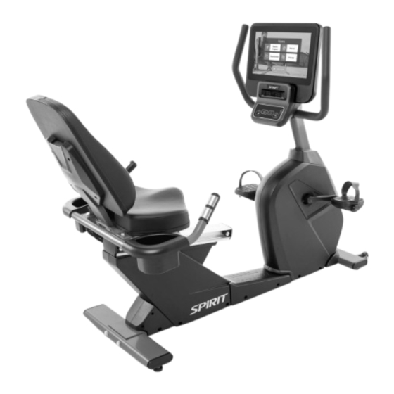
- Page 1 CR800 ENT+ Recumbent Bike OWNER’S MANUAL Please carefully read this entire manual before operating your new recumbent bike.
-
Page 2: Table Of Contents
TABLE OF CONTENTS Important Safety Instructions………………………………………………………….….……3 Important Electrical Instructions……………………………………………………………..5 Important Operation Instructions……………………………………………………….….…..6 Assembly Instructions………………………………………………………………….….……7 Getting on / off your Recumbent Bike .……….…………………………………………… ..14 Suggested Posture and Seat Adjustment Instruction .……….……………………………15 Operation of Your console…………………………………………………………………….17 Target Heart Rate………………………………………………………………………………38 General Maintenance…………………………………………………………….……………41 Exploded View Diagram and Parts List………………………………………………..…….42 Thank you for purchasing our product, please save these instructions. -
Page 3: Important Safety Instructions
IMPORTANT SAFETY INSTRUCTIONS WARNING –When using an electrical appliance, basic precautions should always be followed, including the following: Read all instructions before using this appliance. DANGER - To reduce the risk of electric shock: Always unplug this appliance from the electrical outlet immediately after using and before cleaning. - Page 4 Wear proper shoes. High heels, dress shoes, sandals or bare feet are not suitable for use on your recumbent bike. Quality athletic shoes are recommended to avoid leg fatigue. WARNING: Injuries to health may result from incorrect or excessive training. ...
-
Page 5: Important Electrical Instructions
IMPORTANT ELECTRICAL INSTRUCTIONS WARNING! NEVER remove any cover without first disconnecting AC power. If voltage varies by ten percent (10%) or more, the performance of your recumbent bike may be affected. Such conditions are not covered under your warranty. If you suspect the voltage is low, contact your local power company or a licensed electrician for proper testing. -
Page 6: Important Operation Instructions
IMPORTANT OPERATION INSTRUCTIONS NEVER operate this recumbent bike without reading and completely understanding the results of any operational change you request from the computer. All users should have medical clearance before starting any rigorous exercise program. This is especially important for persons with a history of heart disease or other high risk factors. -
Page 7: Assembly Instructions
ASSEMBLY INSTRUCTIONS PRE-ASSEMBLY Carefully remove all parts from carton and inspect for any damage or missing parts. If damaged parts are found, or parts are missing, contact your dealer immediately. Locate the hardware package. The hardware is separated into four steps. Remove the tools first. Remove the hardware for each step as needed to avoid confusion. - Page 8 STEP 1 #77 - 3/8" x 19 x1.5T #203 - 3/8" x 23 x 2.0T Flat Washer (6pcs) Curved Washer (2 pcs) #176 - 3/8"× 3/4" Hex Head Bolt (6 pcs) #65 - 3/8” x 135mm Hex Head Bolt (2 pcs) STEP 2 #77 - 3/8"x19 x1.5T #89 - 3/8"×7T...
- Page 9 STEP 3 #76 - 8 x19 x1.5T #68 - 5/16” x 5/8” Flat Washer (6 pcs) Hex Head Bolt (8 pcs) #82 - 5/16”x1.5T #83 - 5/16"×19×1.5T Split Washer (2 pcs) Curved Washer (2 pcs) STEP 4 #98 - M6 x 15mm #99 - M5 x 12mm #105 - 4 x 16mm Phillips Head Screw (4 pcs)
- Page 10 STEP 1 1. Install the Rear Stabilizer (No.7) onto the Main Frame with 2 Bolts (No.65) and 2 Washers (No.203). 2. Secure the Seat Back Bracket (No. 5) to the Seat Carriage (No.4) using 6 Bolts (No.176) and 6 Flat Washers (No.77).
- Page 11 STEP 2 1. To install the Rear Handlebar (No.6) to the Seat Carriage (No.4) use 2 Bolts (No.71), 2 Flat Washers (No.77), and 2 Nylon Nuts (No.89). From the side secure with 2 Bolts (No.175), 2 Flat Washers (No.77), and 2 Nylon Nuts (No.89). 2.
- Page 12 STEP 3 1. Feed the Console Mast Cover (No.31) onto the Console Mast (No.2). 2. Thread the Wires (No. 44, 45, 204, 192, 186, 206) through the Console Mast (No.2). 3. Secure the Console Mast (No.2) to the Main Frame (No.1) using 2 Bolts (No.68) and 2 Curved Washers (No.83) from the back of the Mast.
- Page 13 STEP 4 1. Secure the Seat (No.61) to the Seat Carriage (No.4) using 4 Screws (No.98) using the Philips Screwdriver (No.114). 2. Connect the Wires on the back of the console to their respective places: Computer Cable (No.44), Handpulse Wire (No.45), CSAFE Connecting Wire (No.204), Network Connecting Cable (No.192), HDMI Connecting Wire (No.186) and TV Signal Cable (No.206).
-
Page 14: Getting On / Off Your Recumbent Bike
Getting on / off your Recumbent Bike IMPORTANT The Recumbent Bike comes with a Stationary Handlebar & Seat Handlebar. Always hold the Stationary Handlebar or Seat Handlebar when getting on and off the Recumbent Bike. First time users should familiarize themselves with using the Recumbent Bike by using the Stationary Handlebar first and then progressing to the Seat Handlebar. - Page 15 Suggested Posture: Sit straight on the saddle, grab the handle with both hands, position the feet on pedal through the pedal strap. Seat Adjustment Instruction: Height Adjustment Pull adjusting lever upward to slide the seat to a proper position and then push down the lever to fix the position.
-
Page 16: Operation Of Your Console
OPERATION OF YOUR CONSOLE Touchscreen Adjustable fan angle Tablet-friendly reading rack Charging port Start, Stop, and Level controls How to connect with the Bluetooth Click of the Bluetooth icon to enter the pairing page. The system will be searching the available BT signal device around the recumbent bike. - Page 17 STARTING OPERATION When the power is turned ON, the screen will show a brief loading screen and then display the Home Screen which indicates that the machine is ready to operate. Home Screen: Begin operation by touching the icons. Quick operating buttons are conveniently located for basic recumbent bike functions. CSAFE FEATURE Your console is equipped with a CSAFE feature.
- Page 18 FUNCTIONS OF THIS RECUMBENT BIKE The Touchscreen is used for operating all functions. You can directly touch any button on the screen or through quick button on the bottom to control functions. On the lower portion of the console there is the Start button to begin the workout, Stop button to pause/stop programs, Level button to change workload.
- Page 19 TOUCHSCREEN OPERATION LANGUAGE There are 13 languages to choose from. Select your desired language by tapping it on the screen. Once selected, the system will return to the Home Screen with your new language being used. To return to the Home Screen without selecting a new language, press the Home button in the upper left corner of the screen.
- Page 20 ENTERTAINMENT OPTIONS From the Home Screen, tap Entertainment to go to the entertainment menu. You will be given the options of Screen Mirroring and TV mode interface. There are two sources under the TV mode: from the Set-Top Box (STB) or antenna. TV Mode When properly connected to the Set-Top Box (STB) via the HDMI port and TV mode selected, you can enjoy TV programs after selecting TV mode from the Entertainment screen on your recumbent...
- Page 21 SCREEN MIRRORING When Screen Mirroring is selected from the Entertainment screen, you may begin pairing your device. Screen Mirroring displays your phone's screen on the touchscreen of the recumbent bike. Please note that your device must be running iOS 8 or higher. 1.
- Page 22 Android 1. Connect your phone or tablet to the facility’s WiFi. 2. Scan the QR code or search for “Spirit Mirroring” in the Google Play store on your phone or tablet. 3. Download the app. 4. Open the Spirit Mirroring App and select the device name. Then, click Start Mirroring to complete the screen mirroring process.
- Page 23 ENTERING A PROGRAM & CHANGING SETTINGS When the Exercise Programs button is selected from the Home Screen, the screen displays a menu of the different programs available: Manual, Hill, Fat Burn, Cardio, HIIT, Interval, Heart Rate, Custom, Constant Power, and Fitness Test. To select and start a preset program: Select a program by tapping it on the screen, then press Enter to begin.
- Page 25 EXERCISE PROGRAM CHANGING THE WORKOUT DISPLAY During your workout, you may change the display based on the view that works best for your needs. Once your workout begins, you will see 3 preset views available at the bottom of the screen: Simple, Track, and Dashboard.
- Page 26 EXERCISE PROGRAM DASHBOARD To switch the display to Dashboard view, simply tap the Dashboard button at the bottom of the screen. This view shows a virtual dashboard mimics a typical recumbent bike display with information that corresponds with the current workout. Metrics such as elapsed Distance, Calories/Hr, Calories, Total Time, Heart Rate, and RPM are displayed as well as other exercise data.
- Page 27 MANUAL The level of resistance is controlled by the user. Increase or decrease levels at any time during your workout.
- Page 28 HILL This program follows a triangle or pyramid type of gradual progression from approximately 10% of maximum effort (the level that you chose before starting this program) up to a maximum effort which lasts for 10% of the total workout time, then a gradual regression of resistance back to approximately 10% of maximum effort.
- Page 29 CARDIO This program presents a quick progression up to near maximum resistance level (default or user input level). It has slight fluctuations up and down to allow your heart rate to elevate, and then recover repeatedly, before beginning a quick cool down. This will build up your heart muscle and increase blood flow and lung capacity.
- Page 30 CONSTANT POWER A watts program is a controllable constant power whose level adjusts when the speed is changed. Choose either faster pedaling at a lower resistance level or slower pedaling at a higher resistance level. HEART RATE The default value is 65% of your projected rate maximum. You have the option of changing your target heart rate.
- Page 31 CUSTOM You will create the desired resistance levels for each of the 20 segments of the program using the keyboard on the screen. You may change these levels at any time during the workout. TO BEGIN A CUSTOM PROGRAM: 1. Select the Custom program then press the Enter key to begin customizing the program with your personal data, or just press the Start key to begin the program with the default settings.
- Page 32 HIIT PROGRAM The HIIT, or High Intensity Interval Training, program takes advantage of the latest trend in fitness. During the program you will perform short bursts of high intensity sprinting followed by short rest periods. HIIT is a fully customizable interval training program. You can enter the number of intervals, time of each interval Sprint and Rest periods and the work intensity of the levels.
- Page 33 FITNESS TEST The VO2 program is based on the YMCA protocol and is a sub-maximal test that uses pre-determined, fixed work levels that are based on your heart rate readings as the test progresses. The test will take anywhere between 6 to 15 minutes to complete, depending on your level of fitness. The test ends when your heart rate reaches 85% of maximum at any time during the test or your heart rate is between 110 bpm and 85% at the end of two consecutive stages.
- Page 34 Workload chart for male or very fit female: Stage kgm/min < 90 90 - 105 > 105 Stage kgm/min kgm/min kgm/min HR <120 120-135 HR >135 HR <120 120-135 HR >135 HR <120 120-135 HR >135 1350 1200 1050 1200 1050 1050 stage...
- Page 35 Before the Test: Make sure you are in good health; check with your physician before performing any exercise if you are over the age of 35 or persons with pre-existing health conditions. Make sure you have warmed up and stretched before taking the test. ...
- Page 36 What your score means: VO2max Chart for males and very fit females 18-25 26-35 36-45 46-55 56-65 years years years years years years excellent >60 >56 >51 >45 >41 >37 good 52-60 49-56 43-51 39-45 36-41 33-37 above average 47-51 43-48 39-42 35-38...
-
Page 37: Target Heart Rate
TARGET HEART RATE The old motto, “no pain, no gain”, is a myth that has been overpowered by the benefits of exercising comfortably. A great deal of this success has been promoted by the use of heart rate monitors. With the proper use of a heart rate monitor, many people find that their usual choice of exercise intensity was either too high or too low and exercise is much more enjoyable by maintaining their heart rate in the desired benefit range. - Page 38 RATE OF PERCEIVED EXERTION There are more variables involved in how hard you should workout than just heart rate. Your stress level, physical health, emotional health, temperature, humidity, the time of day, the last time you ate and what you ate, all contribute to the intensity at which you should workout. The rate of perceived exertion (RPE), also know as the Borg scale, was developed by Swedish physiologist G.A.V.
- Page 39 Normally the transmitter will be oriented so the Spirit Fitness logo is right side up. 7. The antenna that picks up your heart rate is very sensitive. If there is an outside noise source, turning the whole machine 90 degrees may de-tune the interference.
-
Page 40: General Maintenance
GENERAL MAINTENANCE 1. Wipe down all areas in the sweat path with a damp cloth after each workout. 2. If a squeak, thump, clicking or rough feeling develops the main cause is most likely one of two reasons: a. The hardware was not sufficiently tightened during assembly. All bolts that were installed during assembly need to be tightened as much as possible. - Page 41 EXPLODED VIEW DIAGRAM...
- Page 42 PARTS LIST Q’ty Dwg # Part description Main Frame Console Mast Handle Bar Seat Carriage Seat Back Bracket Handle Bar Rear Stabilizer Crank Axle Seat Wheel Adjustment Plate (L) Seat Wheel Adjustment Plate (R) Idler Wheel Assembly Seat Stop Axle Seat Position Latch Backing Plate Aluminum Track...
- Page 43 Q’ty Dwg # Part description board Power Adaptor Control Power Board EMS Controller 150mm_Connecting Wire,Power Cord Crank Arm(L) Crank Arm® 6004_Bearing 6203_Bearing Drive Belt Induction Brake Magnet(Ø 15×7T) Seat Seat Back Handgrip Foam 3/8" × 135mm_Hex Head Bolt(30mm) 1/4" × UNC20 × 3/4"_Hex Head Bolt 5/16"...
- Page 44 Q’ty Dwg # Part description Ø 13.5 × 30mm_Spring 4 × 16mm_Sheet Metal Screw 5/16" × UNC18 × 1-3/4"_Button Head Socket Bolt M10 × P1.25 × 10T_Nut M5 × P0.8 × 10L_Flat Phillips Head Screw 12/14mm_Wrench Phillips Head Screw Driver Pedal Ø...
- Page 45 Q’ty Dwg # Part description Rubber Pad Network Connecting Cable 1350mm_Sensor W/Cable AC Electronic Module 200mm_Ground Wire 80mm_Connecting Wire (White) 80mm_Connecting Wire (Black) 1500mm_Connecting Wire(Black) 1500mm_Connecting Wire (White) Chain Cover Attaching Plate 300mm_Computer Cable Ø 3/8" × 23 × 2.0T_Curved Washer 1400mm_CSAFE Connecting Wire 300mm_Ground Wire TV Signal Cable...
Need help?
Do you have a question about the CR800ENT+ and is the answer not in the manual?
Questions and answers