
Related Manuals for Midtronics Celltron START+


Summary of Contents for Midtronics Celltron START+
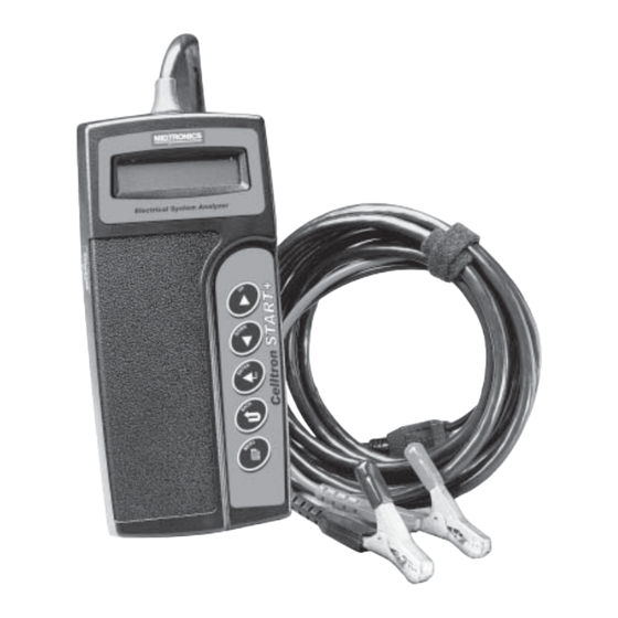
- Page 1 Battery Management Innovation Electrical System Analyzer For testing 6- and 12-volt engine crank/ generator starting, automotive, and marine batteries and 12- and 24-volt charging systems. INSTRUCTION MANUAL...
-
Page 2: Table Of Contents
TABLE OF CONTENTS TEST PREPARATION ............... 3 OUT-OF-VEHICLE TESTING ............. 3 IN-VEHICLE TESTING ............... 3 CONNECTING THE ANALYZER ..........3 USING THE KEYPAD ................ 4 SELECTING A TEST MODE ............. 4 SELECTING A TEST OPTION ............5 ENTERING BATTERY INFORMATION ..........5 TESTING THE BATTERY PACK ............ - Page 3 MENU OPTIONS ................12 VIEW RESULTS ............... 12 PRINT RESULTS ..............12 VOLTMETER ................13 SET ADDRESS ................ 13 PERFORM TEST ..............13 ADDITIONAL FEATURES .............. 14 SYSTEM SAVER ..............14 SURFACE CHARGE REMOVAL ..........14 TEMPERATURE COMPENSATION ........14 BEFORE AND AFTER CHARGE TESTS ........
-
Page 4: Test Preparation
TEST PREPARATION CAUTION: Because of the possibility of personal injury, always use extreme caution when working with batteries. Follow all BCI (Battery Council International) safety recommendations. OUT-OF-VEHICLE TESTING • Clean the battery terminals with a wire brush before testing. • For Group 31 batteries, clip onto the lead pads or install and tighten the lead terminal adapters provided with the analyzer. -
Page 5: Using The Keypad
USING THE KEYPAD USING THE KEYPAD Press the ARROW buttons to scroll through menu choices. Press the ENTER button to make selections. Press the BACK button to move to the previous step. Press the MENU button to make the following options available: •... -
Page 6: Selecting A Test Option
SELECTING A TEST OPTION If you select the In-Vehicle test, the Celltron START+ offers the following options: FULL SYSTEM prompts you through testing the battery pack, the individual batteries, the starting system and the charging system. BATTERY PACK tests the condition of the battery pack and provides the option to test batteries individually. -
Page 7: Testing The Battery Pack
• CA—Cranking Amps. Used in southern climates, where some batteries are rated at 32º F. • MCA—Marine Cranking Amps. For testing marine batteries rated at 32º F. • JIS—Japanese Industrial Standard. Shown on a battery as a combination of numbers and letters. For example, 8D26. BATTERY RATING Once the battery rating system has been selected, scroll to the rating specified on the battery (for example, 625 CCA). -
Page 8: Battery Pack Test Results
BATTERY PACK TEST RESULTS The analyzer will display the open circuit voltage, the cranking amps (units are based on the rating system you selected), and a decision in the following format: 12.62 V 1685 CCA GOOD BAT.PACK • GOOD BAT.PACK—The battery pack is in good shape when compared with its rating while being compensated for cable and connector resistance. -
Page 9: Test Code
• REPLACE BATTERY—Although a battery evaluated as “replace” may still start the vehicle, it no longer measures up to its minimum standard and will fail soon. • BAD CELL-REPLACE—Replace the battery and retest to perform a complete system analysis IMPORTANT: A REPLACE BATTERY result may mean a poor connection exists between the vehicle’s cables and the battery. -
Page 10: Starter System Test Results
• Air—The vehicle has an air starter. This selection will bypass the starting (electrical) system test. You will be prompted to start the engine, and then press ENTER to continue. The analyzer will proceed to the Charging System Test. • Conventional—The vehicle has a conventional electrical starter. - Page 11 The Celltron START+ displays real-time alternator output voltage: Press ENTER to begin the Charging System Test. Testing at rev: The analyzer will prompt you to rev the engine for 5 seconds. When the analyzer has detected the rev, it will collect data and show that it detected the rev.
-
Page 12: Charging System Test Results
CHARGING SYSTEM TEST RESULTS The Analyzer will display several screens including charging system decision, charging system problem detail, load voltage measure- ments, and alternator ripple evaluation. Charging System Decision • CHARGING SYSTEM NORMAL—The charging system is operating within a normal voltage range. •... -
Page 13: Menu Options
MENU OPTIONS To access one of the menu options below, press and hold the MENU button. In the Option Menu use the ARROW buttons to scroll to the desired option and press ENTER to select it. IMPORTANT: The last test results will be lost when you start a new test. -
Page 14: Voltmeter
VOLTMETER The Analyzer can also function as a voltmeter. The operating range of the voltmeter is 0 to 30 volts. IMPORTANT: If the analyzer is connected to a voltage source greater than 30 volts, the circuit board might be damaged. To use the voltmeter function, press and hold the MENU button. -
Page 15: Additional Features
ADDITIONAL FEATURES SYSTEM SAVER While the analyzer is powered only by its internal 9-volt battery (i.e., the clamps are not connected to a 12-volt battery or pack), the analyzer will power-off after 20 seconds (except while printing) if no keypad selections are made. This helps prolong the life of the inter- nal battery. -
Page 16: Glow Plug Detection
Note: When testing a battery installed in a vehicle that has recently been driven, use the Before Charge Test. GLOW PLUG DETECTION If necessary during the Charging System Test, the analyzer will ask you if the vehicle has glow plugs. Choose the appropriate selection by scrolling with the ARROW buttons, then press ENTER. -
Page 17: Troubleshooting
TROUBLESHOOTING DISPLAY PROBLEMS If the display does not turn on: • Check the connection to the vehicle battery or pack. • The vehicle battery may be too low to power the analyzer (below 1 volt). Fully charge the battery and retest. •... -
Page 18: Printing Problems
To turn the printer on, briefly press the MODE button. The green STATUS light should turn on. Make sure you are using the Midtronics printer provided with the analyzer. Other printers may not be compatible. -
Page 19: Replacing The Analyzer Battery
If you are unable to print after ensuring the analyzer is functioning, the printer is on, the battery is good, and the IR transmitter and receiver are aligned, check the printer manual for further instructions or call Midtronics at 800-776-1995 for assistance. REPLACING THE ANALYZER BATTERY... - Page 20 NOTES • •...
- Page 21 NOTES • •...
-
Page 22: Patents, Limited Warranty, Service
PATENTS Made in the U.S.A. by Midtronics, Inc. and is protected by one or more of the following U.S. Patents: 6,469,511; 6,456,045; 6,445,158; 6,441,585; 6,392,414; 6,323,650; 6,316,914; 6,310,481; 6,304,087; 6,249,124; 6,225,808; 6,163,156; 6,091,245; 6,051,976; 5,831,435; 5,821,756; 5,757,192; 5,592,093; 5,585,728; 5,572,136;... - Page 23 PN 168-848A 8/03 ©2003 Midtronics, Inc.
Need help?
Do you have a question about the Celltron START+ and is the answer not in the manual?
Questions and answers