
Related Manuals for TE Connectivity RAYCHEM RBK-X1


Summary of Contents for TE Connectivity RAYCHEM RBK-X1
- Page 1 1 P a g e Page | 1 Customer Manual RBK-X1 / RBK-X1C Heat Shrink Machine Operating manual no. 409-35022 Language: English Rev:...
- Page 2 TE Connectivity/Raychem only obligations are those in the Standard Terms and Conditions of Sale for this product and in no case will TE Connectivity/Raychem are liable for any incidental, indirect or consequential damages arising from the sale, resale, use or misuse of the product.
- Page 3 RBK-X1 / RBK-X1C Rev. D2 07 Mar 2024 Disposal: RBK processor (RBK-X1 & RBK-X1C) This product must not be disposed of as municipal waste. Amendment Record Change Revision Content Amended by Date Request Involve X1 and X1C, CE version, and Cham Zhu Jun.
-
Page 4: Table Of Contents
RBK-X1 / RBK-X1C Rev. D2 07 Mar 2024 Table of Contents Introduction ..............................5 General Information ........................... 6 Front Panel ..............................7 Rear Panel ..............................9 Safety ................................11 General Warnings ............................. 11 Electrical Safety ............................12 Personal Safety ............................13 2.3.1 Eyes .............................. - Page 5 RBK-X1 / RBK-X1C Rev. D2 07 Mar 2024 Operation mode ............................37 4.2.1 Stand-by mode ..........................37 4.2.2 Single Process mode (Main Interface) ---- See section 4.2.7 ............37 4.2.3 Sequence Production mode ---- See section 3.2 & 3.3 ..............37 4.2.4 Remote production mode ---- See section 3.8 .................
-
Page 6: Introduction
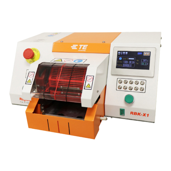
RBK-X1 / RBK-X1C Rev. D2 07 Mar 2024 Introduction This manual applies to RBK-X1 and RBK-X1C processor: (In this manual RBK processor will stand for both RBK-X1 and RBK-X1C): Table 1: General View Air- Centering Picture TE PN cooling Device 2234800-1 --------- RBK-X1 STD 1-2234800-3... -
Page 7: General Information
RBK-X1 / RBK-X1C Rev. D2 07 Mar 2024 General Information The RBK processor is semi-automatic units using an infrared process to heat shrink tubes like… (allows using the machine for ALL tubes in range, TE and non-TE) onto ultrasonically welded or crimped splices. The equipment is designed to operate in conjunction with ultrasonic welders, positioned adjacent to the welding head. -
Page 8: Front Panel
RBK-X1 / RBK-X1C Rev. D2 07 Mar 2024 Front Panel (Controls and Major Components) RBK-X1 Figure 1: Front Panel RBK-X1C Figure 2: Front Panel NOTE In Figure 1, Item 1~10, apply for both RBK-X1 & RBK-X1C and in Figure 2 Item 11~15, apply only for RBK-X1C. - Page 9 RBK-X1 / RBK-X1C Rev. D2 07 Mar 2024 1. Emergency Stop (Cuts power to processor) 2. I/O Switch (Switch to heater. Off--standby, Flash—warm up, Lit—temperature reach set value) 3. Cycle Start Push buttons (Press and hold both buttons simultaneously 0.5s to start cycle process. Interrupt Cycle----see section 3.6 item4, when switch ON this function, to press both start button during cycle would interrupt the cycle.
-
Page 10: Rear Panel
RBK-X1 / RBK-X1C Rev. D2 07 Mar 2024 Rear Panel RBK-X1 Figure 4: Rear Panel RBK-X1C Figure 5: Rear Panel NOTE In Figure 4, Item 1~11, apply for both RBK-X1 & RBK-X1C and in Figure 5 Item 12~13, apply only for RBK-X1C. - Page 11 RBK-X1 / RBK-X1C Rev. D2 07 Mar 2024 1. Ethernet Port. (Access to upgrade program to PLC and touch screen) 2. USB port. (USB connection hole. Communicate with HMI, like barcode scanning and data collection) 3. CD port. (Connect to centering device via CD cable, item 12.) 4.
-
Page 12: Safety
RBK-X1 / RBK-X1C Rev. D2 07 Mar 2024 Safety In common with all electrical equipment, the RBK processor must be used in accordance with established safe working practices. Prior to using the equipment, carefully read the Installation and Operating instructions (Section 4), together with the following safety warnings. -
Page 13: Electrical Safety
RBK-X1 / RBK-X1C Rev. D2 07 Mar 2024 Electrical Safety The equipment is connected to an AC mains electricity supply. Before undertaking any maintenance or repair, always turn off the equipment and ensure it is isolated from the AC supply. Allow the equipment to cool. -
Page 14: Personal Safety
Do not try to put hands into the safety guard, it could cause crush and cut. 2.3.6 Servicing When carrying out repairs, always follow the instructions contained in this manual or contact TE Connectivity for further advice. A record should be kept of the maintenance and servicing of the equipment. -
Page 15: Warnings And Labels
RBK-X1 / RBK-X1C Rev. D2 07 Mar 2024 Warnings and Labels The RBK processor carries a label (shown below) which displays the product part number (PCN), product description, electrical rating information. Figure 6 The following conventions are used in the manual. Information to prevent personal injury from electrical hazard. -
Page 16: Software
RBK-X1 / RBK-X1C Rev. D2 07 Mar 2024 Software The software serves as the processor's central control unit. W ith this you can set the procedures for product processing. The software is operated via a touch screen. When power on to heater, you would see the main interface like this picture. - Page 17 RBK-X1 / RBK-X1C Rev. D2 07 Mar 2024 Table 2 No log on Access right for setting item Main Interface (Single production) Sequence production Production setting Auto Cal. Heat parameter Sequence setting Maintenance Manual Cal. Remote Error Log System Parameter Circle Test I/O &...
-
Page 18: Main Interface
RBK-X1 / RBK-X1C Rev. D2 07 Mar 2024 Main interface Figure 7: Touch Screen (main interface) Figure 7 This picture above (see ) is showing the main interface. In this page, operator can process single production. 1. Processor Status Indicator (Illuminated amber when processor not ready for production. - Page 19 RBK-X1 / RBK-X1C Rev. D2 07 Mar 2024 11. Current cooling cycle time (Display countdown for cooling cycle time. Value will show 0 when cooling function inactivated.) 12. Target production volume (It will pop up reminder when production volume reach target value. See section 3.5 production setting.) 13.
-
Page 20: Heat Parameter
RBK-X1 / RBK-X1C Rev. D2 07 Mar 2024 Heat parameter In this interface, operator can pre-set or edit heat parameters (product description / Temperature / Heating cycle time / Cooling cycle time) stored in the 10X quick process buttons. Figure 8 To edit the parameter stored in quick process button (for example): 1. -
Page 21: Sequence Production
RBK-X1 / RBK-X1C Rev. D2 07 Mar 2024 Sequence production In this interface, processor entry the Sequence production mode. Figure 9 To operate processor as sequence 1# (for example): Click on this icon to have drop down list, to select the Sequence 1#. It would show the selected button, which originally stored in ... -
Page 22: Sequence Setting
RBK-X1 / RBK-X1C Rev. D2 07 Mar 2024 Sequence Setting In this interface, operator can pre-set or edit parameter stored in each Sequence. NOTE: Currently, processor can store up to 15X sequences. Each sequence contains up to 10X processes. Figure 10 To edit the parameter stored in Sequence (for example): 1. -
Page 23: Production Setting
RBK-X1 / RBK-X1C Rev. D2 07 Mar 2024 Production Setting Figure 11 1. Count, production counter. (The number here will +1 automatically after each cycle is completed. The counter won’t count the cycle which was interrupted.) 2. Set, target production volume ... -
Page 24: Maintenance
RBK-X1 / RBK-X1C Rev. D2 07 Mar 2024 Maintenance Figure 12 1. Standby Time Default value: 60 mins. The processor will automatically entry standby mode if no action in 60min. Input value “0”, will turn OFF this function. 2. Processor Calibration Counter No matter which value Count down by cycle (default value: 75000 pcs) or by Hour (default value: 350 Hours). - Page 25 RBK-X1 / RBK-X1C Rev. D2 07 Mar 2024 8. Key lock switch Switch OFF, operator can select other process by press on the 10X quick process button. Switch ON, processor won’t response when operator press on the 10X quick process button. 9.
-
Page 26: Auto Calibration
RBK-X1 / RBK-X1C Rev. D2 07 Mar 2024 Auto Calibration Refer to section 4.6.1 to prepare calibration tool. Figure 13 RBK-X1 “Set Value” °C @ 15S. RBK processor calibration temperature and cycle time. Factory setting: 500 RBK-X1 “Current” RBK processor real temperature and cycle time. (When calibration cycle start, cycle time will count down from 15S to 0S.) Probe “Cal Temp”... -
Page 27: Manual Calibration
RBK-X1 / RBK-X1C Rev. D2 07 Mar 2024 Manual Calibration Refer to section 4.6.1 to prepare calibration tool. Figure 14 RBK-X1 “Set” °C @ 15S. RBK processor calibration temperature and cycle time. Factory setting: 500 RBK-X1 “Current” RBK processor real temperature and cycle time. (When calibration cycle start, cycle time will count down from 15S to 0S.) Manual Calibration Procedure 1. -
Page 28: Remote Operation Mode
RBK-X1 / RBK-X1C Rev. D2 07 Mar 2024 Remote Operation Mode The remote operation mode allows the processor to be controlled by external devices such as an industrial Computer or Ultrasonic Welding equipment. The TE heat shrink machine was tested and proved functional with the major ultrasonic welding machine available in the markets, consult with TE for any communication difficulty occurs. -
Page 29: Remote Operation Procedure
RBK-X1 / RBK-X1C Rev. D2 07 Mar 2024 The checksum hex (A-F) must be in ASCII lower case. The Processor will ignore all RS232 data until a SOH character is recognized. On receipt of a SOH, 10 additional characters or an EOT character is sought. For each character received (including the SOH) the longitudinal addition (checksum) is maintained up to and including byte 11. -
Page 30: System Parameter
RBK-X1 / RBK-X1C Rev. D2 07 Mar 2024 NOTE Refer to section 3.6 item 5, about how to de-active air-cooling function. Then cooling time will display 0. To edit the air-cooling time, click on the hidden button under SNOW icon, to access to the COOLING TIME SETTING page. -
Page 31: Error Log
RBK-X1 / RBK-X1C Rev. D2 07 Mar 2024 3.11 Error Log This page will show error message on HMI. Other processor issue please find from section 4.3 Troubleshooting Table 4 Error Possible Reason Action The processor isn't powered off in right process 1. -
Page 32: Circle Test
RBK-X1 / RBK-X1C Rev. D2 07 Mar 2024 T/P to side/center 1. Check the sensor 1. T/P side/center sensor error. alarm! 2. Reconnect the outer CD cable 2. Outer connection of CD cable fail Push tube failure! 1. Push tube sensor error. 1. -
Page 33: I/O & Manual
RBK-X1 / RBK-X1C Rev. D2 07 Mar 2024 3.13 I/O & Manual Figure 18 Figure 19 This is an I/O page, help FSE to check processor status or do maintenance. 1. When pressing on left start button, this icon will illuminate green. 2. -
Page 34: Centering Manual
RBK-X1 / RBK-X1C Rev. D2 07 Mar 2024 3.14 Centering Manual Figure 20 This is an I/O page when input signal from those action. 1. When detection arms swing up, this icon will illuminate green. 2. When detection arms swing down, this icon will illuminate green. 3. -
Page 35: Barcode Scanning
RBK-X1 / RBK-X1C Rev. D2 07 Mar 2024 3.15 Barcode scanning Barcode scanning can help processor to get the product’s heating parameter (Temperature/time…) by reading the barcode attached on the product, then upload and change current heating parameter to processor accordingly. -
Page 36: Data Collection
RBK-X1 / RBK-X1C Rev. D2 07 Mar 2024 3.16 Data Collection Data Collection is designed to implement the storage of production data, for example: scan ID, product info, temperature, time, date and so on. Production data could be stored to USB stick or external PC through using this feature. Figure 21: (A connection instance of the data transition) NOTE Processors have default setting (parameter, doc format, …) on data collection. -
Page 37: Installation And Operation
RBK-X1 / RBK-X1C Rev. D2 07 Mar 2024 Installation and Operation Installation 4.1.1 Unpacking Remove the RBK processor from its packing. If there is any sign of damage, return the equipment to TE in its original container. Note: The Serial Number on processor must correspond with the Serial Number on the packaging. 4.1.2 Safety CAUTION RBK processor must be installed in accordance with established safe working practices. -
Page 38: Operation Mode
RBK-X1 / RBK-X1C Rev. D2 07 Mar 2024 Operation mode 4.2.1 Stand-by mode When turn on the main power switch, the I/O button LED start to flash, processor is in stand-by, no power is connected to the heater, fan and motor circuits. Currently the processor is showing standby interface and ready to power ON by press on I/O button for 5 second. -
Page 39: Switch On/Off To Processor
RBK-X1 / RBK-X1C Rev. D2 07 Mar 2024 4.2.6 Switch ON/OFF to processor Figure 22: Switch ON/OFF OFF/ ON Switch ON procedure 1. Connect the power input socket with 230V (+/-10%) AC by power cord. 2. Release the Emergency Stop button. 3. -
Page 40: Single Process Operation
RBK-X1 / RBK-X1C Rev. D2 07 Mar 2024 4.2.7 Single Process Operation CAUTION Denotes a condition that can result in product or equipment damage. Figure 23: Single process (RBK-X1 & RBK-X1C) 1. Log on in HMI, switch OFF to the ‘Centering’ button in Maintenance page, to inactivate Auto Centering function (see section 3.5, item 10). -
Page 41: Auto Centering Operation
RBK-X1 / RBK-X1C Rev. D2 07 Mar 2024 4.2.8 Auto Centering Operation CAUTION Action of the Process Start buttons is inhibited until the heater LED has changed to green. Figure 24: Auto Centering (RBK-X1C only) Offset Knob Detection plate Splice length Knob To trigger Auto Centering function: 1. -
Page 42: Emergency Stop
RBK-X1 / RBK-X1C Rev. D2 07 Mar 2024 3. Press on both start buttons simultaneously until the heater carrier move forward to load position. Note: If turn on “Auto Trigger” button in Maintenance page, operator don’t need to press both start button to activate heater carrier moving forward, it would automatically move forward when detection success. -
Page 43: Heater Carriage Jammed
RBK-X1 / RBK-X1C Rev. D2 07 Mar 2024 1. To Power OFF the processor in an emergency, push the EMERGENCY STOP button. If the heater chamber is forward when STOP is activated, it will move to the rear and eject the splice being processed. All power to the Processor is then turned OFF. -
Page 44: Emergency Heater Chamber Release
RBK-X1 / RBK-X1C Rev. D2 07 Mar 2024 4.2.11 Emergency Heater Chamber Release This is an EMERGENCY procedure used in the unlikely event of The Heater Chamber not opening when the Emergency stop is activated. The equipment is connected to an AC mains electricity supply. Before undertaking any maintenance or repair, always turn off the equipment and ensure it is isolated from the AC supply. -
Page 45: Routine Maintenance
RBK-X1 / RBK-X1C Rev. D2 07 Mar 2024 4.2.12 Routine Maintenance The RBK processor requires only the minimum of maintenance. However, the following checks must be carried out on a weekly basis: 1. Check the cooling fan is operating correctly and air is flowing through the rear vent panel. If necessary, clean the dust inside the machine by air gun. -
Page 46: Troubleshooting
RBK-X1 / RBK-X1C Rev. D2 07 Mar 2024 Troubleshooting THE TASKS IN THIS SECTION SHOULD ONLY BE CARRIED OUT BY A SUITABLY QUALIFIED TECHNICIAN. BEFORE STARTING ANY REPAIRS, THE PROCESSOR MUST BE DISCONNECTED FROM THE MAINS SUPPLY. AFTER COMPLETION, THE APPROPRIATE SAFETY CHECKS MUST BE MADE. - Page 47 RBK-X1 / RBK-X1C Rev. D2 07 Mar 2024 Problem Possible Cause Verification Solution Heater chamber Heater not in rear Check heater chamber Remove obstruction. fails to move when position. position. Press cycle start start buttons Check for obstruction. buttons to return pressed.
- Page 48 RBK-X1 / RBK-X1C Rev. D2 07 Mar 2024 Problem Possible Cause Verification Solution ‘Load’ proximity Check that the ‘Load’ Heating chamber moves forward Adjusting sensor and returns immediately to the sensor permanently sensor internal LED position. Replace Home position. 'OFF' or defective. sensor if necessary.
-
Page 49: Recommended Spare Parts
RBK-X1 / RBK-X1C Rev. D2 07 Mar 2024 Recommended Spare Parts Refer to section 4.5.2 Gaining Access, how to remove the cover to replace below spare parts. Mostly all RBK processor can share same spare parts, except those items specify in note column. Table 6 Description Picture... - Page 50 RBK-X1 / RBK-X1C Rev. D2 07 Mar 2024 Description Picture Part No Note Calibration socket, “K” Refer to section 1.2, item 6 2234973-1 type Kit, thermocouple All RBK processor 2391335-1 connector Use on RBK-X1C Connection cable, CD 2369601-4 Refer to section 1.4, item 12 Use on RBK-X1C 2369601-3 or A/C version...
- Page 51 RBK-X1 / RBK-X1C Rev. D2 07 Mar 2024 Description Picture Part No Note Use on NON-CE version 2408011-1 Wire kit, drag chain, X1 (NON-CE) Use on CE version 2408011-2 Wire kit, drag chain, X1 (CE) 2234963-1 Use on NON-CE version Cooling Fan (220V) Use on CE version 2234963-2...
- Page 52 RBK-X1 / RBK-X1C Rev. D2 07 Mar 2024 Description Picture Part No Note 2234964-1 Only used on 2234964-1/-2 CPU module, 2234800-1, -2, -11 programmed 2376800-1, -2 2234966-1 Only used on PLC ASSY 2234964-2 Analog input 2234800-13, -14 module 2376800-13, -14 2234965-1 Communication Locate in Right cover...
- Page 53 RBK-X1 / RBK-X1C Rev. D2 07 Mar 2024 Description Picture Part No Note Use on RBK-X1C 6-2369604-9 Locate in top middle cover Valve, centering plate Use on RBK-X1C 6-2369604-7 Locate in top middle cover Cylinder, Detection plate Use on RBK-X1C 4-2369604-5 Cylinder, Centering Locate in CD cover...
-
Page 54: Repair
RBK-X1 / RBK-X1C Rev. D2 07 Mar 2024 Repair THE TASKS IN THIS SECTION SHOULD ONLY BE CARRIED OUT BY A SUITABLY QUALIFIED TECHNICIAN. THE PROCESSOR MUST BE ALLOWED TO COOL AND BE DISCONNECTED FROM THE MAINS SUPPLY BEFORE CARRYING OUT ANY REPAIR OR REPLACEMENT. -
Page 55: Gaining Access
RBK-X1 / RBK-X1C Rev. D2 07 Mar 2024 4.5.2 Gaining Access To gain access to the internal components, the side and top covers must be removed. Use the correct size Key. Figure 30 Top Rear cover R-side guard Left cover Top front cover L-side guard Top middle cover... - Page 56 RBK-X1 / RBK-X1C Rev. D2 07 Mar 2024 Figure 33: Top Rear Cover Securing Screws (4X) Left Cover Securing Screws (7X) Right Cover Securing Screws (7X)
- Page 57 RBK-X1 / RBK-X1C Rev. D2 07 Mar 2024 Figure 34: L-side guard (2X) and R-side guard (2X) securing screws. Figure 35: CD cover Securing Screws (4X)
-
Page 58: Heater Element Replacement
RBK-X1 / RBK-X1C Rev. D2 07 Mar 2024 4.5.3 Heater Element Replacement ENSURE THAT MAINS SUPPLY IS DISCONNECTED. The two heater elements are mounted within a protective cage. Each are removed separately but must be replaced as a set. REMOVE TOP GUARD FIRST. Replacement procedure 1. -
Page 59: Plc Or Hmi Replacement
RBK-X1 / RBK-X1C Rev. D2 07 Mar 2024 4.5.4 PLC or HMI replacement CAUTION It is important to do additional setting on HMI after replacing the new PLC or HMI. Contact with TE to get the highest authority D, then access to SYSTEM PARAMETER interface, and click on NEXT page icon on bottom right to get the hidden page as below capture. -
Page 60: Optional Accessories
RBK-X1 / RBK-X1C Rev. D2 07 Mar 2024 6. Autorun Default setting OFF. It is customized Autorun function, ONLY available on customized machine 1-2234800-1. OPTIONAL ACCESSORIES Below option components were not included in standard processor. Customers need to purchase from TE Please consult with product manager for PN on TBD item. -
Page 61: Rbk Fixture
RBK-X1 / RBK-X1C Rev. D2 07 Mar 2024 Figure 40 4.6.3 RBK Fixture Table 9 2234786-1 RBK fixture 2234786-2 RBK fixture, with air-cooling kit Figure 41 NOTE More detail on RBK fixture, refer to Instruction Sheet 408-35188. -
Page 62: Air Cooled Stub Splice Fixture
RBK-X1 / RBK-X1C Rev. D2 07 Mar 2024 4.6.4 Air Cooled Stub splice fixture Table 10 981721-000 Air Cooled stub splice fixture (TE PN: 1-1197585-9) 1-529533-7 Air-cooling kit (air flow controller) Figure 42 4.6.5 Other accessories Table 11 2234781-1 Barcode Scanner 2369598-1 USB Flash, 16 GB with adapter (NON-CE) -
Page 63: Specification
RBK-X1 / RBK-X1C Rev. D2 07 Mar 2024 Specification Table 13 Model Designation RBK-X1 RBK-X1C Electrical Supply 230V(+/-10%) - 50 Hz(+/-1Hz) ) Can connect to 110V via optional transformer 2234986-1 N/A (4~6 bar, for A/C version) 4~6 bar Pressure air Supply Power Consumption 3 A (Maximum) Operating Temperature Range... -
Page 64: Schematic Diagram
RBK-X1 / RBK-X1C Rev. D2 07 Mar 2024 Schematic Diagram. NOTE Check on Figure 1, for different kind of version machine. (CE, NON-CE, W/ A/C, W/O A/C, W/ CD, W/O CD) Figure 43... - Page 65 RBK-X1 / RBK-X1C Rev. D2 07 Mar 2024...
- Page 66 RBK-X1 / RBK-X1C Rev. D2 07 Mar 2024...
- Page 67 RBK-X1 / RBK-X1C Rev. D2 07 Mar 2024...
- Page 68 RBK-X1 / RBK-X1C Rev. D2 07 Mar 2024...
- Page 69 RBK-X1 / RBK-X1C Rev. D2 07 Mar 2024...
- Page 70 RBK-X1 / RBK-X1C Rev. D2 07 Mar 2024...
- Page 71 RBK-X1 / RBK-X1C Rev. D2 07 Mar 2024...
- Page 72 RBK-X1 / RBK-X1C Rev. D2 07 Mar 2024...
- Page 73 RBK-X1 / RBK-X1C Rev. D2 07 Mar 2024...
-
Page 74: Pneumatic Diagram
RBK-X1 / RBK-X1C Rev. D2 07 Mar 2024 Pneumatic Diagram Apply only on RBK-X1C... -
Page 75: Replacement And Repair
Stock and control a complete inventory to prevent lost time when replacement of parts is necessary. Parts other than those listed should be replaced by TE Connectivity to ensure quality and reliability. Order or return parts through your TE representative or go to TE.com... -
Page 76: Declaration Of Conformity Of Ce
RBK-X1 / RBK-X1C Rev. D2 07 Mar 2024 Declaration of conformity of CE... - Page 77 RBK-X1 / RBK-X1C Rev. D2 07 Mar 2024...
Need help?
Do you have a question about the RAYCHEM RBK-X1 and is the answer not in the manual?
Questions and answers