Table of Contents
Advertisement
Quick Links
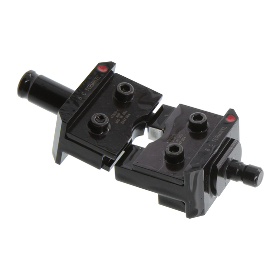
Crimping Dies; PN 47820 thru 47825, 47915, and 47918 (Typical)
Part Number
1. INTRODUCTION
Crimping Dies 47820 through 47823 are used with Crimping Head 69051 or Hand Tool 59974--1. Crimping
Dies 47824, 47825, 47915, and 47918 are used with Crimping Head 69066. The dies crimp pre-insulated
AMPOWER* terminals onto wire sizes 4 through 1/0 AWG, TERMINYL* terminals and splices onto wire sizes 8
through 4/0 AWG, TERMINYL splices with step-down adapters onto wire sizes 16-14 through 1/0 AWG, and
PLASTI-GRIP* terminals and splices onto wire sizes 8 through 4/0 AWG. Refer to Figure 1 to ensure
compatibility of crimping die, head or tool, and wire size.
NOTE
Dimensions in this document are in millimeters [with inches in brackets]. Figures and illustrations are for reference only and
are not drawn to scale.
For detailed information about the head or tool, refer to the instructions packaged with the head or tool.
Reasons for reissue of this instruction sheet are provided in Section 8, REVISION SUMMARY.
2. DESCRIPTION
(FIGURE 1)
Each crimping die consists of a stationary die (nest) and a moving die (anvil). The stationary die features a
locator. Each die contains a color code dot that matches the color code of the terminal and splice. When
mated, the dies form a crimping chamber.
© 2016 TE Connectivity Ltd. family of companies.
All Rights Reserved.
*Trademark
TE Connectivity, TE connectivity (logo), and TE (logo) are trademarks. Other logos, product, and/or company names may be trademarks of their respective owners.
Crimping Dies; PN 47820 thru
47825, 47915, and 47918
Crimping Die
Color Code Dot
47820
Red
47821
Blue
47822
Yellow
47823
Red
47824
Blue
47825
Yellow
47915
Red
47918
Blue
PRODUCT INFORMATION 1-800-522-6752
Wire Size
Head or Tool
(AWG)
8
Hydraulic Crimping Head 69051
6
or
4
Hydraulic Hand Tool 59974-1
2
1/0
2/0
Hydraulic Crimping Head 69066
3/0
4/0
Figure 1
This controlled document is subject to change.
For latest revision and Regional Customer Service,
visit our website at www.te.com.
Instruction Sheet
408-1729
Rev K
22 NOV 16
1 of 11
Advertisement
Table of Contents

Related Manuals for TE Connectivity 47820


Summary of Contents for TE Connectivity 47820
- Page 1 1 of 11 All Rights Reserved. For latest revision and Regional Customer Service, visit our website at www.te.com. *Trademark TE Connectivity, TE connectivity (logo), and TE (logo) are trademarks. Other logos, product, and/or company names may be trademarks of their respective owners.
-
Page 2: Installation
408-1729 3. DIE INSTALLATION AND REMOVAL DANGER To avoid personal injury, ALWAYS release hydraulic pressure to hose or control and disconnect power unit from power supply before installing or removing dies. 3.1. Installation 1. Remove latch pin and open yoke on crimping head (see Figure 2). Figure 2 2. -
Page 3: Crimping Procedure
408-1729 4. CRIMPING PROCEDURE 4.1. Crimping Terminals DANGER Avoid personal injury. When operating tool or power unit, exercise caution while holding terminals or wire near crimping area. 1. Strip wire to the dimensions listed in Figure 3. Do not nick or cut the wire strands. Figure 3 2. - Page 4 408-1729 6. Holding the terminal in place, close the yoke and insert the latch pin. CAUTION Be sure latch pin is fully inserted, otherwise damage to the die and tool or head will occur when the tool or power unit is activated.
- Page 5 Note that the end of the splice containing the adapter has a different color code. Use the crimping die for the larger wire size to crimp both ends of the splice. For example, use Crimping Die 47820 (for wire size 8 AWG) to crimp both ends of the splice with step-down adapter for stepping down from wire size 8 to 16-14 AWG.
- Page 6 408-1729 6. Holding the splice in place, close the yoke and insert the latch pin. CAUTION Be sure latch pin is fully inserted, or damage to the dies and tool or head will occur when the tool is activated. 7. Holding the wire in place, activate tool or power unit to complete first wire barrel crimp. 8.
-
Page 7: Crimp Inspection
Torque (4) Screws in Accordance with Figure 8. Screw Torque Setting Screw Torque Setting Crimping Die Wire Size Crimping Die Wire Size Specification Specification (AWG) (AWG) (inch-pounds) (inch-pounds) 47820 47824 47821 47825 47822 47915 47823 47918 Figure 8 7 of 11 Rev K... - Page 8 408-1729 Figure 9 8 of 11 Rev K...
- Page 9 408-1729 6.1. Daily Maintenance It is recommended that each operator of the dies be made aware of-and responsible for-the following steps of daily maintenance: 1. Remove dust, dirt, and other contaminants with a clean brush, or a soft, lint--free cloth. Do NOT use objects that could damage the dies.
-
Page 10: Replacement And Repair
Order replacement parts through your TE Connectivity Representative, or call 1-800-526-5142, or send a facsimile of your purchase order to 1-717-986- 7605, or write to: CUSTOMER SERVICE (038-035) TE CONNECTIVITY CORPORATION P.O. BOX 3608 HARRISBURG, PA 17105—3608 NOTE Dies may be returned for evaluation and repair. - Page 11 Figures, and CAUTIONS in SECTIONS 6 and 8. Revised quantities of Items 2, 3, 5, 6 in Figure 12. VIEW A VIEW B Replacement Parts Part Numbers for Crimping Die View A View B Item Description 47820 47821 47822 47823 47824 47825 47915 47918 Assy 47941...
- Page 12 Mouser Electronics Authorized Distributor Click to View Pricing, Inventory, Delivery & Lifecycle Information: TE Connectivity 47820 47821...
Need help?
Do you have a question about the 47820 and is the answer not in the manual?
Questions and answers