Table of Contents
Advertisement
Quick Links
© 2022 TE Connectivity family of companies
All Rights Reserved
TE Connectivity, TE connectivity (logo), and TE (logo) are trademarks. Other logos, product, and/or company names may be trademarks of their respective owners.
High Force 20 (HF-20) Terminator, PN 2335500-[ ]
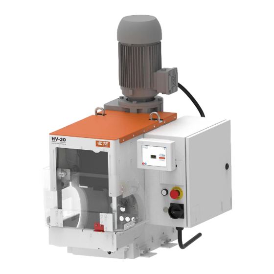
High Voltage 20 (HV-20) Terminator, PN 2348822-[ ]
High Voltage 20 Vision (HV20V) Terminator, PN 2399816-[ ]
INTRODUCTION .................................................................................................................. 4
DESCRIPTION ..................................................................................................................... 5
2.1. By model ..................................................................................................................... 5
2.2. Functional .................................................................................................................... 6
2.3. Electrical ...................................................................................................................... 8
2.4. Machine guard ............................................................................................................. 9
RECEIVING INSPECTION AND INSTALLATION ............................................................. 11
3.1. Receiving inspection ................................................................................................. 11
3.2. Installation ................................................................................................................. 11
3.3. Considerations affecting placement of bench machines ........................................... 12
3.4. Electrical connection ................................................................................................. 14
OPERATION ....................................................................................................................... 15
4.1. Control panel ............................................................................................................. 15
4.2. Membrane keypad and display screen ...................................................................... 18
4.3. Mode selection .......................................................................................................... 21
4.4. Adjusting motor speed ............................................................................................... 21
4.5. Applicator installation ................................................................................................ 22
4.6. Setup ......................................................................................................................... 22
4.7. Adjusting the crimp height ......................................................................................... 23
PREVENTIVE MAINTENANCE .......................................................................................... 23
5.1. Cleaning .................................................................................................................... 23
5.2. Lubrication ................................................................................................................. 24
5.3. Safety system check ................................................................................................. 25
ADJUSTMENTS ................................................................................................................. 27
6.1. Shut height ................................................................................................................ 27
6.2. Guard insert ............................................................................................................... 28
MACHINE OPTIONS .......................................................................................................... 29
7.1. Air feed valve kit (PN 2372210-1) ............................................................................. 30
7.2. Vacuum system ......................................................................................................... 33
7.3. Manual cable clamp .................................................................................................. 34
7.4. Automatic cable clamp .............................................................................................. 35
TROUBLESHOOTING ....................................................................................................... 41
8.1. Error codes ................................................................................................................ 41
8.2. Diagnostics ................................................................................................................ 42
IDENTIFYING THE SOFTWARE VERSION ...................................................................... 43
DISPOSAL .......................................................................................................................... 44
REPLACEMENT AND REPAIR ......................................................................................... 44
RESTRICTION ON HAZARDOUS SUBSTANCES (ROHS) INFORMATION ................... 44
REVISION SUMMARY ....................................................................................................... 44
TOOLING ASSISTANCE CENTER 1-800-722-1111
This controlled document is subject to change.
For latest revision and Regional Customer Service,
visit our website at www.te.com.
Customer Manual
409-35009
JAN 2022 Rev E
20
1 of 44
Advertisement
Table of Contents

Related Manuals for TE Connectivity HF-20


Summary of Contents for TE Connectivity HF-20
-
Page 1: Table Of Contents
1 of 44 All Rights Reserved For latest revision and Regional Customer Service, visit our website at www.te.com. TE Connectivity, TE connectivity (logo), and TE (logo) are trademarks. Other logos, product, and/or company names may be trademarks of their respective owners. - Page 2 409-35009 SAFETY PRECAUTIONS — AVOID INJURY Safeguards are designed into this application equipment to protect operators and maintenance personnel from most hazards during equipment operation. However, certain safety precautions must be taken by the operator and repair personnel to avoid personal injury, as well as damage to the equipment. For best results, application equipment must be operated in a dry, dust-free environment.
- Page 3 409-35009 Figure 1: HF-20 and HV-20 terminators High Force 20 (HF-20) High Voltage 20 Vision (HV20V) High Voltage 20 (HV-20) Table 1: Part numbers Terminator Description part number 2335500-1 High Force 20 terminator (400v) 2335500-2 High Force 20 terminator (200v)
-
Page 4: Introduction
409-35009 INTRODUCTION Read and understand the entire manual before using the equipment. When reading this manual, pay special attention to DANGER, CAUTION, and NOTE statements. DANGER Denotes an imminent hazard that can result in moderate or severe injury. CAUTION Denotes a condition that can result in product or equipment damage. NOTE Highlights special or important information. -
Page 5: Description
HV-20 Terminator 2348822-[ ] Revision D and HV-20V Terminator 2399816-[ ] are equipped with a pneumatic assembly and controls to allow the use of the automatic cable clamp of the HV Modular Die Holder 2305470-2. It does not work on the HF-20 Terminator 2335500-[ ] or the HV-20 Terminator 2348822-[ ] Revision C and earlier. -
Page 6: Functional
409-35009 2.2. Functional These machines provide the force required to crimp terminals in the applicator. A terminal is attached to the wire by placing the wire in the crimp area and pressing the foot switch. The machine consists of three functional areas: ... - Page 7 409-35009 The base plate provides the mounting surface on which the applicator is installed. The external knob allows access to base plate locking feature for easy installation and removal of the applicator (Figure 3). Figure 3: Base plate Base plate Applicator release knob 7 of 44 Rev E...
-
Page 8: Electrical
Both machines include an AC power disconnect switch, a guard control button, an emergency stop push button, and a safety reset push button (Figure 4). Figure 4: Electrical controls HF-20 HV-20 / HV-20V Safety reset... -
Page 9: Machine Guard
409-35009 2.4. Machine guard A guard system is installed to protect the operator while maintaining proper visibility of the work area. The guard system consists of two parts: An upper guard that opens vertically to provide access to load a terminal and wire or cable into the crimping area ... - Page 10 409-35009 To open the lower guard, complete the following steps: 1. Open the upper guard. 2. Press the Lower Guard Release latch (Figure 6). A spring plunger pushes the lower guard open slightly. 3. Release the Lower Guard Release latch. The lower guard falls open. A rubber stop under the guard stops it at the bottom of its travel.
-
Page 11: Receiving Inspection And Installation
409-35009 RECEIVING INSPECTION AND INSTALLATION 3.1. Receiving inspection These machines are thoroughly inspected during and after assembly. A final series of inspections are made to insure the proper machine functioning before packaging and shipping. Despite careful packaging, damage may occur during shipping. Upon receipt, remove the machine from the crate and carefully inspect for damage. -
Page 12: Considerations Affecting Placement Of Bench Machines
409-35009 3.3. Considerations affecting placement of bench machines The location of the machine in relation to the operator's position is extremely important in terms of both safety and maximum efficiency. Studies have repeatedly shown that operator fatigue is reduced, and greater efficiency achieved, if all of the following are true: ... - Page 13 409-35009 Bench The bench to be used should be of sturdy construction, preferably with rubber mounts to minimize noise. A height of 762 to 812 mm [30 to 32 in.] is the most suitable for operator comfort and convenience. This height allows the operator to rest both feet on the floor, providing for the shifting of weight and leg position.
-
Page 14: Electrical Connection
409-35009 Foot switch When the operator is correctly positioned in front of a machine equipped with a foot switch, the foot should rest comfortably on the switch. The foot switch should be movable, so that its location can be readily changed when the operator shifts position to minimize fatigue. -
Page 15: Operation
4.1. Control panel HF-20 Terminator The HF-20 Terminator includes a membrane keypad and display screen for operator control of the terminator. Operation of the machine using the membrane keypad is described in section 4.2. On HF- 20 terminators equipped with an optional Crimp Quality Monitor (CQM) kit, terminator operation is still controlled using the membrane keypad. - Page 16 409-35009 3. Configure the Cycle Options (Figure 13). Auto Raise Guards: When this option is selected, the guards automatically open after a crimp cycle is completed. If CQM is in use and a defective crimp is detected, the guards don’t open until the crimp error is cleared.
- Page 17 409-35009 b. Dismiss the virtual keypad by pressing the X button (Figure 15). Figure 15: Dismissing the virtual keypad 17 of 44 Rev E...
-
Page 18: Membrane Keypad And Display Screen
409-35009 4.2. Membrane keypad and display screen The membrane keypad (Figure 16) is used to set up and operate the machine. The buttons operate as described in Table 3. Figure 16: Membrane keypad Table 3: Membrane buttons Button Name Description Decrease Speed Decrease the motor speed* for normal cycle operations and for jogging. - Page 19 409-35009 Machine status / error code display Table 4: Membrane keypad status codes Code Meaning Machine is ready to cycle Emergency Stop system is not ready. Twist and pull out the Emergency Stop button, then press the white safety reset push button. Machine guards are open, or cycling is inhibited by the Crimp Quality Monitor (if attached).
- Page 20 409-35009 Additional controls Figure 17 shows the additional controls. The operation of the controls is described in Table 6. Figure 17: Additional controls Table 6: Operation of additional controls Control Operation Push button/indicator. Press to turn on the safety circuit, enabling motor operation. Safety reset The indicator shows that the safety circuit is active and motor operation can occur.
-
Page 21: Mode Selection
409-35009 4.3. Mode selection Table 7 describes the three basic modes of operation for this machine. The buttons for selecting a mode are described in Table 3. Table 7: Modes of operation Mode Description Pressing the foot switch (with the guard closed) rotates the crankshaft (at a speed defined by Full cycle the speed control buttons) through a complete revolution. -
Page 22: Applicator Installation
Jog the machine (see Table 7) through a complete crimp cycle. NOTE Do not use wire during this step of the setup process. NOTE The HV-20 and HF-20 machines should be able to jog through the terminal at maximum jog speed. 22 of 44 Rev E... -
Page 23: Adjusting The Crimp Height
409-35009 Inspect the crimped terminal to verify that the terminal is being positioned properly within the applicator. Correct for any positioning errors in accordance with the applicator instruction sheet. Repeat steps 2 and 3 until a terminal is properly positioned. Place a prepared wire in the crimp area and press the foot switch. -
Page 24: Lubrication
409-35009 5.2. Lubrication The moving parts of the machine require regular lubrication to ensure reliable service and long life. Preferred greases are Chevron™ Delo™ ESI™ EP NLGI 2, and Chevron Ulti-Plex™ EP NLGI 2. NOTE Contact TE Engineering for second choice alternatives. NOTE For operation in temperatures below 10°... -
Page 25: Safety System Check
2. Place the system in diagnostic mode (see section 8.2). 3. Close all the guards: Front Guard and Side Guard (if equipped). 4. On the control panel display, verify that the input identifier is ON (Figure 19). Figure 19: Input identifiers for HF-20 Guards interlocks Emergency stop Motor safety stop 5. - Page 26 409-35009 HV-20 Terminators 1. Power ON the system by turning on the AC Disconnect switch. 2. Navigate to the HV-20 diagnostic display (Figure 34). Figure 20: Input identifiers for HV-20 3. Close all the guards: Front Guard and Side Feed (if equipped). 4.
-
Page 27: Adjustments
409-35009 ADJUSTMENTS The following adjustments are necessary to maintain the machine in operating condition, and to set up the machine after replacing parts. DANGER To avoid personal injury, always disconnect electrical and air supplies before performing adjustments. 6.1. Shut height Measuring The shut height is the distance between the bottom portion of the ram post adapter and the top surface of the machine base plate. -
Page 28: Guard Insert
409-35009 Adjusting The shut height is pre-set at the factory and should not require further adjustment unless it is necessary to replace parts. Before you make any changes to the machine, contact your local Field Service Representative, or call the Tooling Assistance Center at 1-800-722-1111. CAUTION Never attempt to adjust the shut height without first trying an applicator that is known to produce terminations of the correct crimp height. -
Page 29: Machine Options
409-35009 MACHINE OPTIONS Table 12 lists the available machine options for the HF-20 and HV-20 Terminator Machines. Refer to the applicable section for installation instructions. Table 12: Machine options Part Description Section Purpose HF-20 HV-20 number Required to run certain types of air feed... -
Page 30: Air Feed Valve Kit (Pn 2372210-1)
409-35009 7.1. Air feed valve kit (PN 2372210-1) Figure 22: Air feed valve kit PN 2372210-1 Port 3: Constant air supply (for use with air feed units with built-in valves Port 2: Cylinder retract connection (throttle acting air cylinder connection) Port 1: Cylinder extend connection (spring return cylinder connection) Air feed cable Flow control adjustment... - Page 31 409-35009 8. Mount the pressure regulator/shut off valve to the terminator frame. 9. Route the air feed cable (Figure 23) through the gap in the rear guard (Figure 24). Figure 23: Air feed cable Figure 24: Routing the air feed cable Route cable with other cables Route cable through opening in guard Route cable through cable gland into electrical enclosure...
- Page 32 409-35009 10. Unscrew the cable gland (Figure 24), using care not to damage the existing wire going through it. 11. Route the air feed cable through the cable gland into the electrical box. 12. Plug the air feed cable into connector J17 on the PC board. 13.
-
Page 33: Vacuum System
409-35009 7.2. Vacuum system To install the vacuum system, proceed as follows: 1. Attach the vacuum system to the left frame plate as shown in Figure 25. Figure 25: Vacuum system 2. Thread the air hose through the rear guard and plug it into the air valve as shown in Figure 26. Figure 26: Threading the air hose Port 2 Vacuum air supply line... -
Page 34: Manual Cable Clamp
409-35009 7.3. Manual cable clamp The manual cable clamp is available on certain die holders. See Figure 27. Figure 27: Manual cable clamps Original style cable clamp New manual style cable clamp Handle NOTE The jaws only help locate the cable. They do not lock the cable in place before or during crimping. They allow the cable to slide in the jaws due to terminal extrusion during crimping. -
Page 35: Automatic Cable Clamp
409-35009 Operation of the new manual clamp To load the cable: 1. Position the cable. 2. Lift the handle. Springs close the jaws. To unload the cable: 1. Push down fully on the handle to open the jaws. The jaws remain open. 2. - Page 36 409-35009 3. Install the air lines in the matching ports: air line 4 in port 4, air line 5 in port 5, air line 6 in port 6 (Figure 29). Figure 29: Air lines and ports Port 6 Port 4 Port 5 4.
- Page 37 409-35009 Automatic cable clamp operation 1. To load the cable: a. Position the cable. b. Lift the handle. Springs close the jaws (Figure 30). NOTE The jaws only help locate the cable. They do not lock the cable in place before or during crimping. They allow the cable to slide in the jaws due to terminal extrusion during crimping.
- Page 38 409-35009 2. Unload the cable. NOTE The setup person can select between manual unload operation and automatic unload operation from the display screen when selecting to use the automatic cable clamp. Manual jaw opening operation: a. Push down fully on the handle (Figure 31) to open the jaws. The jaws remain open. Figure 31: Handle of automatic cable clamp b.
- Page 39 409-35009 4. Press the foot switch to start a terminator cycle and crimp the terminal. The Crimp Quality Monitor analyzes the crimp. If the crimp is determined to be good: a. Open the upper guard by pushing the guard control push button. If manual jaw opening operation was selected, open the jaws by pressing down fully on the handle.
- Page 40 409-35009 The status of the cable clamp jaws is displayed on the display screen (Figure 32). NOTE X superimposed on the clamp icon indicates a sequence error. Figure 32: Status of cable clamp jaws Clamp icon (showing sequence error) Opened Closed Locked 40 of 44...
-
Page 41: Troubleshooting
409-35009 TROUBLESHOOTING Contact the Tooling Assistance Center at 1-800-722-1111. 8.1. Error codes Table 13: Error codes Code Description E001 The host is inhibiting operation. E002 The guard interlock is open. E005 The control panel is not communicating with the CPU board. E020 Movement of the TDC switch was not detected. -
Page 42: Diagnostics
409-35009 8.2. Diagnostics The control panel can be placed in a diagnostic mode to check operation of the machine inputs. HV-20 only Navigate to the Diagnostics screen and click the HV-20 tab (Figure 33). Various indicators are displayed (Table 14). Figure 33: HV-20 tab Table 14: HV-20 input status indicators Icon... -
Page 43: Identifying The Software Version
2. Turn power to the machine ON. When the display on the control panel appears, the control panel software version is displayed briefly, followed by the HV-20 / HF-20 software version. The format for both is X.XX.XX. 43 of 44... -
Page 44: Disposal
Call 800-522-6752. Write to: CUSTOMER SERVICE (038-035) TE CONNECTIVITY CORPORATION PO BOX 3608 HARRISBURG PA 17105-3608 For customer repair services, call 800-522-6752. RESTRICTION ON HAZARDOUS SUBSTANCES (ROHS) INFORMATION Information on the presence and location of any substances subject to RoHS can be found at https://www.te.com/commerce/alt/product-compliance.do.
Need help?
Do you have a question about the HF-20 and is the answer not in the manual?
Questions and answers