Table of Contents
Advertisement
Quick Links
© 2012 Tyco Electronics Corporation, a TE Connectivity Ltd. Company
All Rights Reserved
*Trademark
TE Connectivity, TE connectivity (logo), and TE (logo) are trademarks. Other logos, product and/or Company names may be trademarks of their respective owners.
Crimp Quality Monitor II
1. INTRODUCTION . . . . . . . . . . . . . . . . . . . . . . . . . . . . . . . . . . . . . . . . . . . . . . . . . . . . . . . . 3
2. DESCRIPTION. . . . . . . . . . . . . . . . . . . . . . . . . . . . . . . . . . . . . . . . . . . . . . . . . . . . . . . . . . 5
2.1. Screen Description . . . . . . . . . . . . . . . . . . . . . . . . . . . . . . . . . . . . . . . . . . . . . . . . . . . 5
2.2. Menu Bar . . . . . . . . . . . . . . . . . . . . . . . . . . . . . . . . . . . . . . . . . . . . . . . . . . . . . . . . . . 5
2.3. Control Panel Screen . . . . . . . . . . . . . . . . . . . . . . . . . . . . . . . . . . . . . . . . . . . . . . . . . 6
2.4. Help . . . . . . . . . . . . . . . . . . . . . . . . . . . . . . . . . . . . . . . . . . . . . . . . . . . . . . . . . . . . . . 7
2.5. Screen Information . . . . . . . . . . . . . . . . . . . . . . . . . . . . . . . . . . . . . . . . . . . . . . . . . . . 7
2.6. Graphing Information . . . . . . . . . . . . . . . . . . . . . . . . . . . . . . . . . . . . . . . . . . . . . . . . . 7
2.7. Task Bar . . . . . . . . . . . . . . . . . . . . . . . . . . . . . . . . . . . . . . . . . . . . . . . . . . . . . . . . . . . 7
2.8. Definitions. . . . . . . . . . . . . . . . . . . . . . . . . . . . . . . . . . . . . . . . . . . . . . . . . . . . . . . . . . 7
3. RECEIVING INSPECTION AND INSTALLATION . . . . . . . . . . . . . . . . . . . . . . . . . . . . . . 8
3.1. Receiving . . . . . . . . . . . . . . . . . . . . . . . . . . . . . . . . . . . . . . . . . . . . . . . . . . . . . . . . . . 8
3.2. Inspection and Installation . . . . . . . . . . . . . . . . . . . . . . . . . . . . . . . . . . . . . . . . . . . . . 8
3.3. System Settings . . . . . . . . . . . . . . . . . . . . . . . . . . . . . . . . . . . . . . . . . . . . . . . . . . . . . 8
3.4. CQM II Settings . . . . . . . . . . . . . . . . . . . . . . . . . . . . . . . . . . . . . . . . . . . . . . . . . . . . . 9
4. PRODUCTION RUN SETUP . . . . . . . . . . . . . . . . . . . . . . . . . . . . . . . . . . . . . . . . . . . . . . . 15
4.1. Options . . . . . . . . . . . . . . . . . . . . . . . . . . . . . . . . . . . . . . . . . . . . . . . . . . . . . . . . . . . . 15
4.2. Work Order . . . . . . . . . . . . . . . . . . . . . . . . . . . . . . . . . . . . . . . . . . . . . . . . . . . . . . . . . 16
4.3. Order Size . . . . . . . . . . . . . . . . . . . . . . . . . . . . . . . . . . . . . . . . . . . . . . . . . . . . . . . . . 17
4.4. Part . . . . . . . . . . . . . . . . . . . . . . . . . . . . . . . . . . . . . . . . . . . . . . . . . . . . . . . . . . . . . . . 17
4.5. Analysis Methods . . . . . . . . . . . . . . . . . . . . . . . . . . . . . . . . . . . . . . . . . . . . . . . . . . . . 18
4.6. Crimp Height. . . . . . . . . . . . . . . . . . . . . . . . . . . . . . . . . . . . . . . . . . . . . . . . . . . . . . . . 18
4.7. Peak Force and Work Index Sensitivity . . . . . . . . . . . . . . . . . . . . . . . . . . . . . . . . . . . 19
4.8. Point to Point (P2P) / FFT Sensitivity . . . . . . . . . . . . . . . . . . . . . . . . . . . . . . . . . . . . . 20
4.9. Sample . . . . . . . . . . . . . . . . . . . . . . . . . . . . . . . . . . . . . . . . . . . . . . . . . . . . . . . . . . . . 21
4.10. Calibrate . . . . . . . . . . . . . . . . . . . . . . . . . . . . . . . . . . . . . . . . . . . . . . . . . . . . . . . . . . 21
4.11. Learn. . . . . . . . . . . . . . . . . . . . . . . . . . . . . . . . . . . . . . . . . . . . . . . . . . . . . . . . . . . . . 22
5. PRODUCTION . . . . . . . . . . . . . . . . . . . . . . . . . . . . . . . . . . . . . . . . . . . . . . . . . . . . . . . . . . 24
6. CONTROL PANEL . . . . . . . . . . . . . . . . . . . . . . . . . . . . . . . . . . . . . . . . . . . . . . . . . . . . . . 31
7. TROUBLESHOOTING. . . . . . . . . . . . . . . . . . . . . . . . . . . . . . . . . . . . . . . . . . . . . . . . . . . . 55
8. MAINTENANCE. . . . . . . . . . . . . . . . . . . . . . . . . . . . . . . . . . . . . . . . . . . . . . . . . . . . . . . . . 58
8.1. Touch Screen Cleaning. . . . . . . . . . . . . . . . . . . . . . . . . . . . . . . . . . . . . . . . . . . . . . . . 58
8.2. Daily Maintenance . . . . . . . . . . . . . . . . . . . . . . . . . . . . . . . . . . . . . . . . . . . . . . . . . . . 58
8.3. Special Handling Precautions for the Linear Encoder . . . . . . . . . . . . . . . . . . . . . . . . 58
8.4. Quality Contol Maintennce . . . . . . . . . . . . . . . . . . . . . . . . . . . . . . . . . . . . . . . . . . . . . 59
8.5. Evaluation and Repair . . . . . . . . . . . . . . . . . . . . . . . . . . . . . . . . . . . . . . . . . . . . . . . . 59
9. REVISION SUMMARY. . . . . . . . . . . . . . . . . . . . . . . . . . . . . . . . . . . . . . . . . . . . . . . . . . . . 59
TOOLING ASSISTANCE CENTER
1-800-722-1111
. . . . . . . . . . . . . . . . . . . . . . . . . . . . 2
This controlled document is subject to change.
For latest revision and Regional Customer Service,
visit our website at www.te.com
Customer Manual
409-10100
15 FEB 12 Rev C
1 of 59
LOC B
Advertisement
Table of Contents

Related Manuals for TE Connectivity Crimp Quality Monitor II


Summary of Contents for TE Connectivity Crimp Quality Monitor II
-
Page 1: Table Of Contents
All Rights Reserved 1-800-722-1111 For latest revision and Regional Customer Service, *Trademark visit our website at www.te.com LOC B TE Connectivity, TE connectivity (logo), and TE (logo) are trademarks. Other logos, product and/or Company names may be trademarks of their respective owners. -
Page 2: Safety Precautions Read This First
409-10100 DANGER STOP SAFETY PRECAUTIONS AVOID INJURY Safeguards are designed into this application equipment to protect operators and maintenance personnel from most hazards during equipment operation. However, certain safety precautions must be taken by the operator and repair personnel to avoid personal injury, as well as damage to the equipment. For best results, application equipment must be operated in a dry, dust-free environment. -
Page 3: Introduction
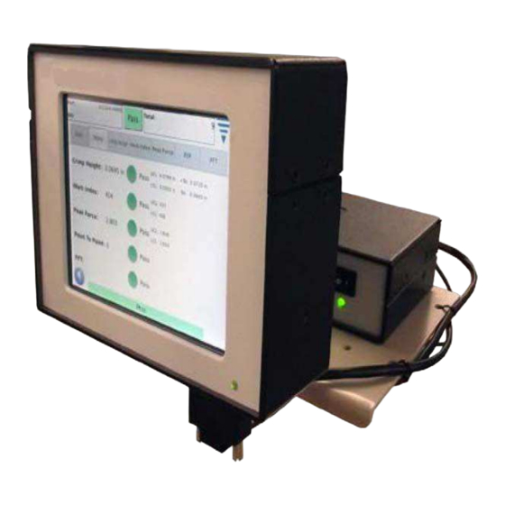
Quality Monitor II (CQM II) applicators or installed into the terminating machine. The Crimp Quality Monitor notifies the operator with visual cues when faulty crimps occur. See Figure 1 to view the CQM II The Crimp Quality Monitor II is a PROCESS monitor. It is influenced by many variables, that include changes in wire, NOTE terminal, applicator terminal condition, operator, environment, etc. - Page 4 AMP 3K/5K Terminating Crimp Quality Monitor II Machine Below is a list of the specifications for the Crimp Quality Monitor II (CQM II). ELECTRICAL Operating Voltage (DC Power Supply) 100 - 240 VAC, 50/60 Hz, 1.5 Amps (Max.) Host and DAQ (data aquisition) operating...
-
Page 5: Description
409-10100 Using the AC power cord that is appropriate with your countries power system (typically included with the system), ensure Using the AC power cord that is appropriate with your countries power system (typically included with the system), ensure NOTE NOTE that the cord is plugged into a circuit that has over-current protection of no greater than 15-20 amps (country dependent). -
Page 6: Control Panel Screen
409-10100 2.3. Control Panel Screen • Touching the Control Panel icon will result in the Control Panel screen. See below • Touching the “Language” icon will result in selecting the appropriate language. Refer to the Control Panel section in Section 6. •... -
Page 7: Help
A. Headroom (and How it Effects Crimps) The Crimp Quality Monitor II monitors the forces that occurs during the crimping process. The forces during a crimp are the combination of forming the crimp profile of the terminal and the compression of the wire strands within the terminal. - Page 8 409-10100 With the “Quick Headroom Check” (described in Paragraph 4.9), you will be able to have a better understanding of how successful Crimp Quality Monitoring will be with the wire and terminal combination you are running. A headroom of greater than 35% is the number you are looking for.
-
Page 9: Receiving Inspection And Installation
3. RECEIVING INSPECTION AND INSTALLATION 3.1. Receiving The Crimp Quality Monitor II (CQM II) is thoroughly inspected during and after assembly. A final series of inspections is made to insure the proper functioning of the Crimp Quality Monitor II before packaging and shipping. - Page 10 409-10100 3.4. CQM Settings The “CQM Settings” refers to the initial setup of the CQM II -- PRIOR to production and is to be performed by the CQM administrator. For system setup information refer to Section 6. Touch the control panel icon to bring up the control panel screen shown below. 10 of 59 Rev C...
- Page 11 409-10100 A. CQM Settings -- Setup Tab Touch the CQM Settings icon to bring up the CQM Settings screen shown below. For the Custom selection, the four outputs can be configured to interface to the intended host machine, including the Crimp Enable output. A non-terminated cable is provided for connection to the host machine.
- Page 12 409-10100 C. CQM Settings -- Force Sensor Tab Choose the Force Sensor tab to select the force sensor that is installed on the terminating machine. Selections are: Piezo Frame and Strain Gauge (base plate). 12 of 59 Rev C...
- Page 13 409-10100 D. CQM Settings -- Sensor Calibration Tab If you have the Analog Height sensor, then you must calibrate it. Select the Sensor Calibration and follow the instructions on the display and enter the Low and High voltages that you measured based on the switch settings of the A/D Calibration Switch.
- Page 14 409-10100 process, you must evaluate the crimp and ensure that it meets your acceptance criteria. The CQM II starts fully analyzing crimps once it is in the Production Mode. For those systems with Crimp Height Monitoring enabled, Crimp Height is evaluated during each learn crimp, so if there is a crimp outside of the tolerance, you will be notified and that crimp will not be used for learning.
-
Page 15: Production Run Setup
409-10100 4. PRODUCTION RUN SETUP 4.1. Options This is the first screen in the task bar. It is also the “home” screen when the home icon is chosen from the menu bar. In order to use the options, select the corresponding radio button. 15 of 59 Rev C... -
Page 16: Work Order
409-10100 4.2. Work Order Using a Work Order is optional list, provide additional detail in printed and saved Reports that the CQM II can provide. To use a Work Order, select the radio button “Specify a Work Order”. You may select an Existing Work Order from the drop down list or edit (create) a new work order. -
Page 17: Order Size
409-10100 4.3. Order Size To use the Order Size counters, select the radio button “Specify Total and Batch Sizes”. Touch the appropriate box Total and Batch sizes and enter the number required. 4.4. Part A part number must be selected. The part number contains the relevant analysis method selections and associated parameters for the product that you want to produce. -
Page 18: Analysis Methods
409-10100 4.5. Analysis Methods Once you touch the Analysis icon, you will notice that the number of selections in the task bar increase to provide more choices for editing parameters for the Analysis methods. First, start by choosing the analysis method(s) for the part. -
Page 19: Peak Force And Work Index Sensitivity
409-10100 Touch the next Sensitivity arrow or the right arrow icon to move to the next task. 4.7. Peak Force (PF) and Work Index (WI) Sensitivity Touch the Up and Down arrows to change the sensitivity settings of the Peak Force and Work Index. Press Default to return the setting to the factory default. -
Page 20: Point To Point (P2P) / Fft Sensitivity
409-10100 4.8. Point to Point (P2P) / FFT Sensitivity Touch the Up and Down arrows to change the sensitivity settings of the Point to Point and FFT. Press Default to return the setting to the factory default. Adjusting the sensitivity to eliminate problems or to enhance performance for these analysis methods is similar to the prior description for Peak Force and Work Index. -
Page 21: Sample
409-10100 4.9. Sample Use the Sample mode to make sample crimps to setup the process. In this task you will install the applicator, load product, and run your initial crimps to set terminal feed and crimp height. The CQM II will graph a crimp curve (provided the force is sufficient) but will not be analyzing the crimp. -
Page 22: Learn
409-10100 4.11. Learn To learn the process, proceed with crimping the number of terminals required for Learn (as entered in the CQM Settings). Carefully inspect each crimp to ensure its quality. If the Crimp is not to your quality requirements, then you can Reject the crimp and do it again. - Page 23 409-10100 . Once you have completed all of the Learn crimps, the display will indicate Process Learned. It is recommended to re-learn the process if something dramatically changes in the process such as changing to a new reel of terminals or a different type of wire. It is also advisable to Re-Learn if while in production you experience too many failures that with further inspection meet your quality requirements.
-
Page 24: Production
After the display indicates Process Learned, you can then proceed to Production. Touch the Production icon or the right arrow icon to move to the next task. The Crimp Quality Monitor II is a PROCESS monitor. It is influenced by many variables that include changes in wire, CAUTION terminal, applicator, terminal condition, operator, environment, etc. - Page 25 409-10100 5.1. Basic Screen (Shown Above) The basic screen, see above, provides a visual indication of the Crimp Status History for selected analysis methods. For each analysis method, the results are shown as: Green for a good crimp, red for a failed crimp, Orange for a Control Limit (not a failure but an indication that the Crimp Height is getting close to the tolerance), and white for a crimp that was not analyzed by that method.
- Page 26 409-10100 5.2. Status The status screen provides individual status indicators for each selected analysis method as well as data that is relevant to the analysis method. If any one analysis method fails, the overall status of the crimp is a Fail. The colors of the indicators are as previously described in the Crimp Status History on the Basic screen.
- Page 27 409-10100 5.3. Crimp Height The Crimp Height screen provides a crimp history graph showing the tolerance limits and the calculated crimp height for each crimp. To see more points than those shown, simply touch the graph to enter a full screen mode and use the arrow keys to move forward and backward in time.
- Page 28 409-10100 5.5. Peak Force The Peak Force screen provides a crimp history graph showing the tolerance limits and the peak force recorded for each crimp. To see more points than those shown, simply touch the graph to enter a full screen mode and use the arrow keys to move forward and backward in time.
- Page 29 409-10100 5.6. P2P The Point-to-Point (P2P) graph on this screen shows the 50 points of the last crimp that are individually analyzed to ensure a good crimp. If any point is outside the tolerance band, then the result of the analysis is a Failure.
- Page 30 409-10100 30 of 59 Rev C...
-
Page 31: Control Panel
409-10100 6. CONTROL PANEL Touching the Control Panel icon on the main menu screen brings up the control panel. The following control panel tools are to be used by the CQM administrator. For System Settings, refer to Paragraph 3.3. For CQM II settings, refer to Paragraph 3.4. NOTE ... - Page 32 409-10100 • Change Password With the user selected from the drop down list, choose Change Password. The user must enter a new password and then verify the password by entering it again. • Delete With the user selected from the drop down list, choose Delete. 32 of 59 Rev C...
- Page 33 409-10100 • Permission Settings Permissions are a method to allow or not allow individual users access to certain tasks or actions that can be performed on the CQM II. With the user selected from the drop down list, choose the appropriate radio button to provide the user permission for the various tasks and actions.
- Page 34 409-10100 A user can always change their own password. The ADMIN user can change any user's password. NOTE (There is no separate permission that would allow a non-ADMIN user to change another users password). D. Locale Settings Touch the icon to select the Locale screen. The thousands separator, decimal symbol, time format, date format, and default units selection can be made in this screen....
- Page 35 409-10100 F. Reports Touch the icon to select the “Reports” screen. The reports screen is a very busy screen and it may be easier to navigate by plugging in a USB NOTE NOTE mouse. 35 of 59 Rev C...
- Page 36 409-10100 The reports screen is a spreadsheet that contains past history of production work orders or parts that have been run. Each NOTE entry is referred to as an “Instance.” The Reports Screen gives access to the data and history of all the crimps analyzed by the CQM unit. The results of every crimp is stored in a database on the unit.
- Page 37 409-10100 • Production Detail View When the detailed data on the production run is displayed each crimp and its results are shown. You will see the Crimp Number, Overall Result, Batch Count, Total Count, Time Stamp, Part Number, Crimp Mode of each individual crimp.
- Page 38 409-10100 Mode Description: SAMPLE_MODE Crimps that are done when the CQM II is in sample mode. In the sample mode no analysis is performed on the crimp and its result in INVALID. CALIBRATE_GAIN_MODE and These are crimps that are done setting the force gain and crimp height CALIBRATE_CRIMP_HEIGHT_ reference.
- Page 39 409-10100 Data Description: CRIMP RESULT DATA INSTANCE ID - production run identifier. CRIMP ID - a unique identifier for the crimp in the production run. OVERALL RESULT - final result of all the analysis methods. BATCH COUNT - number of PASS crimps in the batch after the crimp. TOTAL COUNT - number of PASS crimps in the production run after the crimp.
- Page 40 409-10100 WORK INDEX_HISTORY DATA (WORK INDEX ANALYSIS) WORK INDEX RESULT - PASS or FAIL or LEARN from work index analysis WORK INDEX - work index value from the work index analysis - upper control limit - lower control limit SENSITIVITY - sensitivity setting for the work index analysis P2P HISTORY DATA (POINT TO POINT ANALYSIS) P2P RESULT...
- Page 41 409-10100 41 of 59 Rev C...
- Page 42 409-10100 Raw Data Output File When the “Save Raw Data” button is pressed all the data about the selected production run will be saved to a file. The file is a comma delimited file suitable to be viewed in a spread sheet program like Microsoft Excel. The first and second line shows the Production Run information.
- Page 43 409-10100 H. Curve History Graph Touch the icon to select the Crimp History Graph screen. The Crimp History Graph is a diagnostic tool that displays actual raw data curves for both the force and position sensors. The data is not filtered so a curve may look slightly different from the graphs shown in the other modes.
- Page 44 409-10100 Status Tab Displays the current IP address for the CQM. The Restart Networking button should be used when ever the CQM is connected to a different network while it is already powered up, and will cause the CQM to attempt to configure it's IP address if DHCP is enabled. If connected to a network with a DHCP server, such as a corporate network, or a home internet gateway/ router, the CQM will obtain it's IP address from the DHCP server.
- Page 45 409-10100 J. Display Settings Touch the icon to select the Display Settings screen. You can adjust the display brightness and screen saver time out by touching on the pointer on the slider and dragging it. When the screen saver is active, the display will be dark and the LED on the Host will be amber. Simply touch the display and it will return to the normal operating state.
- Page 46 409-10100 The use of a plastic stylus is recommended for accurate calibration. NOTE The screen indicates where you should touch, but the lower left image is not presented well. It is similar to the other NOTE corners so touching it in a similar manner will suffice.
- Page 47 409-10100 Quit Tab This screen is used to quit the software application. Quitting should only be done following instructions from TE personnel. NOTE Version tab This screen displays the various software versions that are currently installed on the CQM. 47 of 59 Rev C...
- Page 48 409-10100 Firmware Update Tab This screen is used to update the software on the CQM. Follow the onscreen instructions. This should be accomplished ONLY upon instruction of TE personnel NOTE File Operations Tab This screen is used for certain file operations. Follow the on screen instructions. 48 of 59 Rev C...
- Page 49 409-10100 Database Operations Tab This screen is used to backup and restore the system database. Choose the appropriate selection and follow the on screen instructions. Backup to a USB flash drive is provided for secure backup and restoration. M. Diagnostics The Diagnostics section is provided for authorized users to monitor the hardware status of the system.
- Page 50 409-10100 Host I/O Tab The Host I/O screen displays the status of the modules Inputs and Outputs. Output states can be changed by touching the appropriate icon. Do not attempt to change output states without direction from TE personnel. DANGER ...
- Page 51 409-10100 Piezo Tab The Piezo screen provides a means to diagnose the Piezo sensor input. Directions from TE personnel will be provided if this action is required. NOTE CANOpen Node Tab The CANOpen Node screen provides information regarding the CAN address of the attached modules. 51 of 59 Rev C...
- Page 52 409-10100 N. Error Log Viewer The Error Log Viewer provides a list of various errors, system setting changes, etc. that may be useful for diagnosing system problems. Specific instructions will be provided by TE personnel to use this feature. O. Demo The Demo selection is primarily used for demonstration and training purposes.
- Page 53 409-10100 perform the crimp. Data from a stored crimp will be used and all screens will appear as though a normal crimp occurred. P. Printer Icon This screen is used to select the appropriate printer for the CQM. The CQM can print to a local, USB-connected printer, or to some network printers. Printers connected via USB-serial or USB-parallel port adapters are not supported in the CQM.
- Page 54 409-10100 information at the subsequent screens. The printer should now appear in the “Current” printer selection drop down box. It may be necessary to exit the printer setup screen, and reenter it for the printer to appear in the list. Through this web interface, it is possible to configure many different kinds of network printers that cannot be added automatically as outlined above, including Windows printers, HP JetDirect, LPR/LPD, just to name a few.
-
Page 55: Troubleshooting
409-10100 7. TROUBLESHOOTING Problem Possible Cause Corrective Action Invalid Crimps During On terminators with an analog Verify and correct any settings as necessary. Learn. height sensor, the problem can occur if the coefficients are incorrect or have not been entered. Disconnected or damaged cables. - Page 56 409-10100 Additional Information for the Specific Sensors Is the correct Position Sensor selected in CQM Settings? Is the encoder cable connected to the DAQ module? Check for damaged encoder cable. If it is damaged, replace it. The encoder reader head has a LED. If the cable good and is connected to the DAQ module, and the LED is not lit, Linear Encoder replace the encoder.
- Page 57 409-10100 Problem Corrective Action Carefully inspect the crimp. Does it meet your quality criteria? Some problems could be related to poorly maintained tooling. Ensure the tooling is in optimum condition. Too many crimps are failing Adjust the sensitivity of the analysis methods so that they are less sensitive. Experiment by changing the that appear to be good.
-
Page 58: Maintenance
409-10100 8. MAINTENANCE The following procedures have been established to assure the quality and reliability of the CQM. The CQM should be checked daily, and a more detailed inspection should be performed (according to your quality control group) on a regular basis. 8.1. -
Page 59: Quality Contol Maintennce
409-10100 8.4. Quality Control Maintenance Your quality control personnel should perform regular inspections. A record of quality control inspections should remain with the personnel responsible for the CQM. TE recommends one inspection a month; however, operator skill, amount of use, ambient working conditions, and your company’s established standards are all factors in establishing frequency of inspections.
Need help?
Do you have a question about the Crimp Quality Monitor II and is the answer not in the manual?
Questions and answers