
Related Manuals for TE Connectivity 2234800-1


Summary of Contents for TE Connectivity 2234800-1
- Page 1 1 P a g e Page | 1 Customer Manual RBK-X1 PN 2234800-1 Operating manual no. 409-35012 Language: English...
- Page 2 TE Connectivity/Raychem only obligations are those in the Standard Terms and Conditions of Sale for this product and in no case will TE Connectivity/Raychem are liable for any incidental, indirect or consequential damages arising from the sale, resale, use or misuse of the product.
- Page 3 RBK-X1 PN 2234800-1 Disposal: RBK- X1 This product must not be disposed of as municipal waste. Amendment Record Change Rev. Content Amended By Date Request No. Rev. A Initial Release Cham Zhu Sept. 2019 Page 2 Rev A Sept 2019...
-
Page 4: Table Of Contents
RBK-X1 PN 2234800-1 Table of Contents Introduction.......................….5 General Information ..........................5 Front Panel ..............................6 Front Panel-Touch Screen........................7 Rear Panel ..............................8 Safety ...........................10 General Warnings ...........................10 Electrical Safety ............................11 Personal Safety............................12 2.3.1 Eyes ..............................12 2.3.2 Clothing ..............................12 2.3.3 Fire Hazard ............................. .12 2.3.4... - Page 5 RBK-X1 PN 2234800-1 Operation...………………........................29 Stand-by Mode……….…........................29 4.2.1 4.2.2 Single Process Mode (Main interface)……………………………………………………………………….. 29 4.2.3 Sequence Production Mode........................29 4.2.4 Remote Operation Mode..........................29 4.2.5 Switch ON/OFF to processor........................30 4.2.6 Single Process Operation........................31 Emergency Stop……...…........................32 4.2.7 4.2.8 Emergency Heater Chamber Release....................
-
Page 6: Introduction
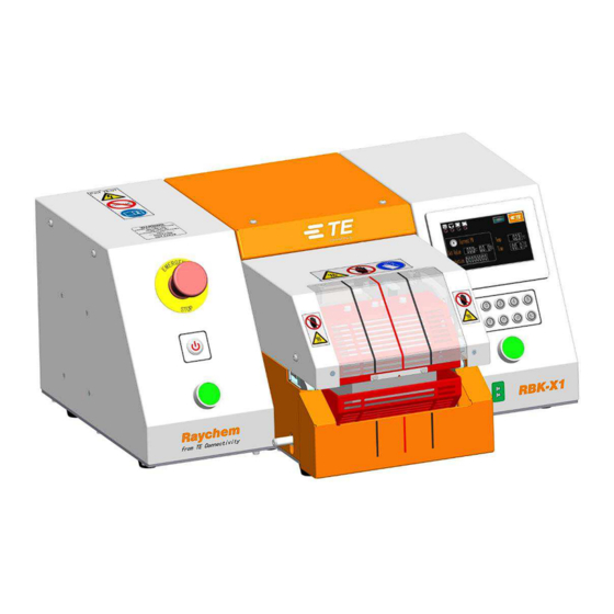
General Information Fig. 1-1: General View The RBK- X1 is semi-automatic units using an infrared process to heat shrink TE Connectivity ILS-125, ILS- 85 and QSZH products onto ultrasonically welded or crimped splices. The equipment is designed to operate in conjunction with ultrasonic welders, positioned adjacent to the welding head. -
Page 7: Front Panel
RBK-X1 PN 2234800-1 Controls and Major Components Front Panel Fig. 1-2: Front Pane 1. Emergency Stop (cuts power to machine) 2. I/O Switch (Off--standby, Flash—warm up, Lit—temperature reach set value) 3. Cycle Start Push buttons (Press and hold both buttons for 0.5 S simultaneously to start cycle process. Or press any start button to interrupt cycle.) 4. -
Page 8: Front Panel-Touch Screen
RBK-X1 PN 2234800-1 Front Panel-Touch Screen Fig. 1-3: Touch Screen ( main interface 1. Heater Indicator (Illuminated amber when heater start to warm up. Illuminated green when heater reach set value. Ready to production.) 2. Calibrate Indicator (Illuminated when calibration required) 3. -
Page 9: Rear Panel
RBK-X1 PN 2234800-1 Rear Panel Fig. 1-4: Rear Panel 1. Ethernet Port (Access to upgrade program to PLC and touch screen) 2. Air Cooling Socket (Connect to air cooling kit 1-529533-7) 3. RS 232 Connector (Connect to welding machine, like Schunk welding machine.) 4. - Page 10 RBK-X1 PN 2234800-1 EMC Protection for connecting external devices to the RBK-X1 Processor. Connecting any external device to the following outputs below a ferrite core must be clamped to every connection used. The ferrite clamp must contain one loop. Connection requiring ferrite clamp WITH ONE LOOP.
-
Page 11: Safety
Failure to follow the manufacturer’s instructions may affect the equipment warranty. Do not use the equipment for cooking food or heating products other than those recommended by TE Connectivity. Due to the processor can reach up to 600° C, do not operate the Processor near combustible liquids or gasses. -
Page 12: Electrical Safety
RBK-X1 PN 2234800-1 Electrical Safety The equipment is connected to an AC mains electricity supply. Before undertaking any maintenance or repair, always turn off the equipment and ensure it is isolated from the AC supply. Allow the equipment to cool. -
Page 13: Personal Safety
2.3.5 Servicing When carrying out repairs, always follow the instructions contained in this manual or contact TE Connectivity for further advice. A record should be kept of the maintenance and servicing of the equipment. Do not use substitute components, use only TE Connectivity approved parts. If the mains (utility) power supply cord is damaged it must be replaced only by a special cord or assembly available from the supplier or its agent. -
Page 14: Warnings And Labels
RBK-X1 PN 2234800-1 Warnings and Labels The RBK-X1 carries a label (shown below) which displays the product part number (PCN), product description, electrical rating information. The following conventions are used in the manual. Information to prevent personal injury. Information to prevent damage to the equipment. -
Page 15: Software
RBK-X1 PN 2234800-1 Software The software serves as the processor's central control unit. With this you can set the procedures for product processing. The software is operated via a touch screen. When power on to processor, you would see the main interface like this picture. - Page 16 RBK-X1 PN 2234800-1 Log on from main interface. Choose the setting item access to below different interface. Circle Test System Parameter Sequence production Error Log Production setting Remote Heat parameter Main Interface Manual calibration Sequence setting Maintenance Auto calibration Page 15...
-
Page 17: Heat Parameter
RBK-X1 PN 2234800-1 Heat parameter In this interface, operator can pre-set/edit heat parameter (product size/heat temperature/heat time) stored in the 10X quick button. To edit the parameter stored in button (for example): 1. Switch , allow the operator to edit the parameter. -
Page 18: Sequence Production
RBK-X1 PN 2234800-1 Sequence production In this interface, processor entry the Sequence production mode. Click on this icon to select the Sequence number. 1#, for example. It would show the selected button, which originally stored in sequence 1# 5). -
Page 19: Sequence Setting
RBK-X1 PN 2234800-1 Sequence Setting In this interface, operator can pre-set/edit Sequence stored in the 15X Sequence. To edit the parameter stored in Sequence: 1. Switch , allow the operator to edit the parameter. 2. Click on this icon to select the Sequence to be edited. 1#, for example. -
Page 20: Production Setting
RBK-X1 PN 2234800-1 Production Setting Production quantity counter. The number here will +1 automatically after each cycle is completed. (The counter won’t count the cycle which was interrupted.) Operator can preset the production target (quantity) here. a. If you input the value, when processor complete the setting production quantity, on the main interface will pop up a tip “complete”, to remind the operator production is completed. -
Page 21: Maintenance
RBK-X1 PN 2234800-1 Maintenance Standby Time, the processor will automatically entry standby mode if no action. Default value: 60 mins, turn OFF this function by input value “0”. Processor Calibration Counter, by cycle (pc) or by Hour. Default value: 75000 pcs / 350 Hours Processor cycle counter, which is designed to indicate the processor operation cycle after leave factory. -
Page 22: Auto Calibration
RBK-X1 PN 2234800-1 Auto Calibration Calibration of the RBK- X1 is carried out by using a UHI 250A probe. (Probe: 288869-000, Extension Cable: 952687-000) 3.6.1 Automatic Calibration Procedure The following procedure describes how to calibrate the Processor, by comparing the expected UHI probe peak temperature with the actual UHI peak temperature recorded after a 15 second cycle. -
Page 23: Manual Calibration
RBK-X1 PN 2234800-1 Manual Calibration 1. Set tool to 500° C and 15 second cycle time. 2. Connect UHI probe to a calibrated meter. 3. Carry out 3 calibration readings (cool UHI to 23°C between each cycle). Calculate average value. -
Page 24: Remote Operation Mode
RBK-X1 PN 2234800-1 Remote Operation Mode The remote operating mode allows the RBK- X1 to be controlled by external devices such as an industrial Computer or Ultrasonic Welding equipment. Remote operation is enabled via the RS232 communication interface, through an RS232 cable connected to the external device. -
Page 25: Rs232 Data Format
RBK-X1 PN 2234800-1 3.8.2 RS232 Data Format All data is transmitted in ASCII form. The Data format uses 8 data bits, 1 stop bit, no parity at 9600 baud. Full duplex TX/RX exists, RTS/CTS is disabled. The RBK- ILS Processor MK3 Processor recognizes the following fourteen bytes information packet structure. -
Page 26: System Parameter
RBK-X1 PN 2234800-1 System Parameter Processor cycle counter. This value cannot be reset. It will record the total cycle after processor leave TE factory. Processor timer. This value cannot be reset. It will record the total operating hours after processor leave TE factory. -
Page 27: Error Log
RBK-X1 PN 2234800-1 3.10 Error Log Error Possible Reason Action The machine isn't powered off in right process 1. Check the emergency stop button was Power off! 1. Emergency stop button be pushed pressed or not 2. The power supply is cut 2. -
Page 28: Circle Test
RBK-X1 PN 2234800-1 3.11 Circle Test This is a testing interface, which was designed to test the RBK-X1 to run cycle in 500 C/0.2S for 60 min. So as to make sure machine work well before leaving factory. To start the circle test: 1. -
Page 29: Installation And Operation
RBK-X1 PN 2234800-1 Installation and Operation Installation 4.1.1 Unpacking Remove the RBK- X1 from its packing. If there is any sign of damage, return the equipment to TE in its original container. Note: The Serial Number on machine must correspond with the Serial Number on the packaging. -
Page 30: Operation
RBK-X1 PN 2234800-1 Operation 4.2.1 Stand-by mode When turn on the main power switch, the I/O button LED start to flash, machine is in stand-by, no power is connected to the heater, fan and motor circuits. Currently the machine is showing standby interface and ready to power ON by press on I/O button for 5 second. -
Page 31: Switch On/Off To Processor
RBK-X1 PN 2234800-1 4.2.5 Switch ON/OFF to processor Switch ON 1. Connect the power input socket with 200~240V AC by power cord. 2. Release the Emergency Stop button. 3. Switch the Mains Switch to ON from rear panel Touch screen will power on and show the standby interface. -
Page 32: Single Process Operation
RBK-X1 PN 2234800-1 4.2.6 Single Process Operation Action of the Process Start buttons is inhibited until the heater LED has changed to green. Operation of any individual Start button during the timer count-down will manually override the process and move the heater chamber to the rear. -
Page 33: Emergency Stop
RBK-X1 PN 2234800-1 4.2.7 Emergency Stop Note: This is an EMERGENCY procedure used in the unlikely event of the Heater Chamber remaining closed after the set time sequence. HAZARDS FROM DAMAGED PRODUCT Due to the nature of all heating tools, any product which is trapped or inadvertently left in the oven can become damaged or even BURN. -
Page 34: Emergency Heater Chamber Release
RBK-X1 PN 2234800-1 4.2.8 Emergency Heater Chamber Release This is an EMERGENCY procedure used in the unlikely event of The Heater Chamber not opening when the Emergency stop is activated. The equipment is connected to an AC mains electricity supply. Before undertaking any maintenance or repair, always turn off the equipment and ensure it is isolated from the AC supply. -
Page 35: Heater Carriage Jammed
RBK-X1 PN 2234800-1 4.2.9 Heater Carriage Jammed Heater Carriage Jams. Power to the motor and heater will remove automatically. The RBK processor heaters will switch off automatically if the carriage has not reached the front sensor in 700ms. Power to the drive motor removed. -
Page 36: Routine Maintenance
RBK-X1 PN 2234800-1 4.2.10 Routine Maintenance The RBK- X1 requires only the minimum of maintenance. However, the following checks must be carried out on a weekly basis: 1. Check the cooling fan is operating correctly and air is flowing through the rear vent panel. -
Page 37: Troubleshooting
RBK-X1 PN 2234800-1 Troubleshooting THE TASKS IN THIS SECTION SHOULD ONLY BE CARRIED OUT BY A SUITABLY QUALIFIED TECHNICIAN. BEFORE STARTING ANY REPAIRS, THE MACHINE MUST BE DISCONNECTED FROM THE MAINS SUPPLY. AFTER COMPLETION, THE APPROPRIATE SAFETY CHECKS MUST BE MADE. - Page 38 RBK-X1 PN 2234800-1 Problem Possible Cause Verification Solution Heater chamber Heater not in rear Check heater chamber Remove obstruction. fails to move when position. position. Press cycle start start buttons Check for obstruction. buttons to return pressed. heater to the rear position.
- Page 39 RBK-X1 PN 2234800-1 Problem Possible Cause Verification Solution ‘Load’ proximity Check that the ‘Load’ Heating chamber moves forward Adjusting sensor and returns immediately to the sensor permanently sensor internal LED position. Replace Home position. 'OFF' or defective. sensor if necessary.
-
Page 40: Recommended Spare Parts
RBK-X1 PN 2234800-1 Recommended Spare Parts The following list contains the spare parts available for the RBK- ILS Processor MK3. Description Picture Part No Note 2234800-1 Main Equipment View Window 2234897-1 Start button 2234980-1 Contact, Start button 2234984-1 Each machine would... - Page 41 RBK-X1 PN 2234800-1 Ejector blade set 2234840-1 (including left and right) Heating Element Assembly 2234991-1 See section (including upper and lower 5.3.2 how to heater, thermocouple is part of replace the lower heater.) heating element Mounting on Thermocouple 2234990-1 lower heating element.
- Page 42 RBK-X1 PN 2234800-1 Emergency Stop Button 2234983-1 Switch 2234985-1 Locate in Right cover PLC Module 2234964-1 Locate in Right Cover Safety Relay 2234967-1 Locate in Right Cover Touch Screen 2234977-1 2234968-1 Locate in left Temperature controller cover Reset Spring, Latch Assembly...
-
Page 43: Repair
RBK-X1 PN 2234800-1 Repair THE TASKS IN THIS SECTION SHOULD ONLY BE CARRIED OUT BY A SUITABLY QUALIFIED TECHNICIAN. THE MACHINE MUST BE ALLOWED TO COOL AND BE DISCONNECTED FROM THE MAINS SUPPLY BEFORE CARRYING OUT ANY REPAIR OR REPLACEMENT. -
Page 44: Gaining Access
RBK-X1 PN 2234800-1 4.5.2 Gaining Access To gain access to the internal components, the side and top covers must be removed. Use the correct size Key. Top Cover Securing Screws (4X) Left Cover Securing Screws (7X) Page 43 Rev A... - Page 45 RBK-X1 PN 2234800-1 Right Cover Securing Screws (7X) Page 44 Rev A Sept 2019...
-
Page 46: Heater Element Replacement
RBK-X1 PN 2234800-1 4.5.3 Heater Element Replacement. ENSURE THAT MAINS SUPPLY IS DISCONNECTED. The two heater elements are mounted within a protective cage. Each are removed separately, but must be replaced as a set. REMOVE TOP GUARD FIRST. Replacement procedure 1. -
Page 47: Optional Accessories
RBK-X1 PN 2234800-1 OPTIONAL ACCESSORIES Below option components were not included in standard machine 2234800-1. Customer need to purchase from TE separately IF NEED. 4.6.1 Calibration tools 288869-000 Standard UHI temperature calibration probe 952687-000 Extension cable 288869-000 952687-000 4.6.2 Power Cord & Transformer... -
Page 48: Centering Device
RBK-X1 PN 2234800-1 4.6.3 Centering Device Centering Device Fixture Software upgrade 4.6.4 Multi-wire Fixture 2234710-1 Multi-wire Fixture 4.6.5 Stub Splice Fixture 2234801-1 Stub Splice Fixture Page 47 Rev A Sept 2019... -
Page 49: Air Cooled Stub Splice Fixture
RBK-X1 PN 2234800-1 4.6.6 Air Cooled Stub splice fixture. 981721-000 Air Cooled stub splice fixture (TE PN: 1-1197585-9) 1-529533-7 Air Cooling kit (air flow controller) 1-529533-7 981721-000 4.6.7 Welding machine interface (Schunk) 2234989-1 Service, Welding machine interface (Schunk) 4.6.8 Barcode Scanner... -
Page 50: Technical Details
RBK-X1 PN 2234800-1 Technical Details Specification RBK- X1 210/240 V - 50 Hz/60Hz Electrical Supply Can connect to 110V via optional transformer ) 2234986-1 Power Consumption 3 A (Maximum) Operating Temperature Range 200ºC to 600ºC Maximum (Acc. ± 1ºC of set temperature) 500°C Recommended...
Need help?
Do you have a question about the 2234800-1 and is the answer not in the manual?
Questions and answers