Advertisement
Quick Links
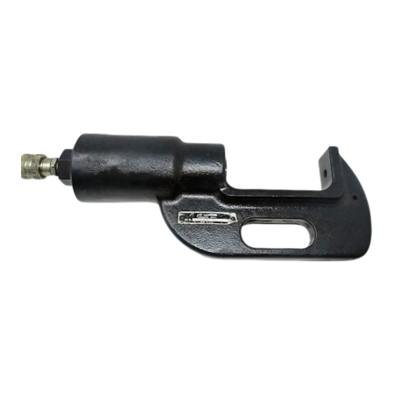
Lock Screw
Lock Screw
in Ram
Flats on
Shank
AMPOWER DISCONNECT TERMINAL CRIMPING DIES
USED IN CRIMPING HEAD
69082 or 1752786-1
46753-3
46758-2
46758-3
68204-1
68206-1
68332-1
Figure 1
1. INTRODUCTION
This instruction sheet provides information on product
application and a maintenance and inspection
procedure for AMPOWER Disconnect Terminal
Crimping Dies listed in the table in Figure 1.
These crimping dies are used to crimp AMPOWER
Quick Disconnect Terminals on wire sizes No. 1/0
through 777 MCM.
Basic instructions on the use of the dies, wire
preparation, etc., are provided in Section 2,
INSTRUCTIONS. Section 3 features a terminal "Crimp
Inspection" procedure, and Section 4 contains
"Maintenance and Inspection Procedures" which will
enable you to maintain a die certification program.
The dies are coated with preservative to prevent rust
and corrosion. Wipe this preservative from the dies,
particularly from the crimping areas.
For further instructions relative to the hydraulic power
unit and hydraulic crimping heads, refer to the
instructions packaged with these tools.
©2013 Tyco Electronics Corporation, a TE Connectivity Ltd. company
All Rights Reserved
*Trademark
TE Connectivity, TE connectivity (logo), and TE (logo) are trademarks. Other logos, product and/or company names may be trademarks of their respective owners.
AMPOWER* Disconnect
Terminal Crimping Dies
Typical Dies
(1/0 Thru 400 MCM)
Stationary Die
Moving Die
Typical Dies
(500-777 MCM)
USED IN CRIMPING HEAD
69099 or 1752868-1
68200-1
68201-1
68203-1
TOOLING ASSISTANCE CENTER 1-800-722-1111
PRODUCT INFORMATION 1-800-522-6752
NOTE
i
NOTE
All dimensions on this document are in metric units [with
U.S. customary units in brackets]. Figures and
illustrations are for identification only and are not drawn
to scale.
Reason for revision is provided in Section 5,
REVISION SUMMARY.
2. CRIMPING PROCEDURES
NOTE
i
NOTE
Crimping Head No. 69082 is illustrated throughout this
document, however, crimping instructions are the same
for 69082, 69099, 1752786-1, or 1752868-1 crimping
heads.
2.1. Die Insertion
DANGER
Avoid personal injury, when using power unit, exercise
caution to avoid accidentally depressing the foot pedals
or trigger control when changing dies.
1. Select the correct dies for wire size being used.
See Figure 2.
2. Loosen the lock screw in the top section of the
crimping head. See Figure 1.
3. Insert the shank of the stationary die into the top
section of the crimping head and tighten the lock
screw. See Figure 1.
NOTE
i
NOTE
Ensure the dies are inserted "fully" nd "flats" on the
shanks are facing the lock screws.
4. Activate the power unit, advance the ram until the
lock screw is visible
5. Loosen the lock screw and insert the shank of the
moving die into the ram. Tighten the lock screw. See
Figure 1.
6. Active the power unit to complete the cycle and
allow the ram to return to the "Down" position.
NOTE
i
NOTE
Observe that the shanks are offset on the 500, 600, and
777 MCM moving and stationary dies. Ensure that the
shank of each die is offset to the same side in order to
maintain the proper mating of dies.
2.2. Die Removal
1. Loosen the lock screw in the top section of the
crimping head and remove the stationary die.
2. Advance the ram until the lock screw is visible.
Loosen the lock screw and remove the dies.
This controlled document is subject to change.
For latest revision and Regional Customer Service,
visit our website at www.te.com
Instruction Sheet
408-2292-3
12 JUL 13 Rev B
1 of 6
Advertisement

Related Manuals for TE Connectivity AMPOWER


Summary of Contents for TE Connectivity AMPOWER
- Page 1 All Rights Reserved PRODUCT INFORMATION 1-800-522-6752 For latest revision and Regional Customer Service, *Trademark visit our website at www.te.com TE Connectivity, TE connectivity (logo), and TE (logo) are trademarks. Other logos, product and/or company names may be trademarks of their respective owners.
- Page 2 408-2292-3 WIRE STRIP LENGTH WIRE DIE SET CRIMPING HEAD SIZE NUMBER NUMBER MINIMUM MAXIMUM 68200-1 69099 23.82 [.938] 25.4 [1.000] 68201-1 69099 23.82 [.938] 25.4 [1.000] 250 MCM 68203-1 69099 39.67 [1.562] 41.28 [1.625] 350 MCM 68204-1 68082 39.67 [1.562] 41.28 [1.625] 400 MCM (2 Crimps) 68332-1...
-
Page 3: Crimp Inspection
408-2292-3 2. Orient all terminals with the dies so the large slot in the terminal is rotated 45° from the vertical as 500, 600, 777 MCM shown in Figure 3B. 3. First Crimp - Position the terminal so the edge of the stationary die is aligned with the outer crimp location mark as shown in Figure 3B(a). - Page 4 408-2292-3 Figure 5 Rev B 4 of 6...
-
Page 5: Maintenance And Inspection Procedures
408-2292-3 4. MAINTENANCE AND INSPECTION PROCEDURES Suggested Plug Gage Design Die Closure TE Connectivity recommends that a maintenance and Configuration GO Dim. NO-GO Dim. inspection program be performed periodically to ensure dependable and uniform terminations. Inspect “B” “B” dies at least once a month. Frequency of inspection may be adjusted to suit your requirements through experience. -
Page 6: Revision Summary
408-2292-3 dimensionally correct. If the die closure does not Inspection of Crimping Die Closure conform with the GO/NO-GO gage conditions, Detail B contact your local TE Representative. 4.4. Replacement Parts Detail A The crimping dies are not repairable. It may be advantageous to stock replacement dies to prevent “GO”...
Need help?
Do you have a question about the AMPOWER and is the answer not in the manual?
Questions and answers