
Related Manuals for TE Connectivity RBK-X1C


Summary of Contents for TE Connectivity RBK-X1C
- Page 1 1 P a g e Page | 1 Customer Manual (Original Instruction) RBK-X1C Heat Shrink Machine PN 2376800-1 Operating manual no. 409-35021 Language: English Rev:...
- Page 2 TE Connectivity/Raychem’s only obligations are those in the Standard Terms and Conditions of Sale for this product. In no case will TE Connectivity/Raychem be liable for any incidental, indirect, or consequential damages arising from the sale, resale, use, or misuse of the product.
- Page 3 RBK-X1C PN 2376800-1 Disposal: RBK-X1C This product must not be disposed of as municipal waste. Amendment Record Change Rev. Content Amended By Date Request No. Rev. A Initial Release John Knoll Dec. 2020 Page 2 Rev. A Dec. 2020...
-
Page 4: Table Of Contents
RBK-X1C PN 2376800-1 Table of Contents Introduction.......................….5 General Information ..........................5 Front Panel ..............................6 Front Panel-Touch Screen........................7 Rear Panel ..............................8 Safety ...........................10 General Warnings ...........................10 Electrical Safety ............................11 Personal Safety............................12 2.3.1 Eyes ..............................12 2.3.2 Clothing ..............................12 2.3.3 Fire Hazard ............................. .12 2.3.4... - Page 5 RBK-X1C PN 2376800-1 Unpacking...………………........................30 4.1.1 Safety…..………………........................30 4.1.2 Location…...………………........................30 4.1.3 4.1.4 Electrical Connection...….........................30 4.1.5 Pneumatic Connections...........................30 Operation Mode…………........................31 Stand-by Mode……….…........................31 4.2.1 Single Process Mode …………………………………………………………………………………………. 31 4.2.2 4.2.3 Sequence Production Mode........................31 4.2.4 Remote Operation Mode..........................31 Auto Centering Mode…..........................31 4.2.5...
-
Page 6: Introduction
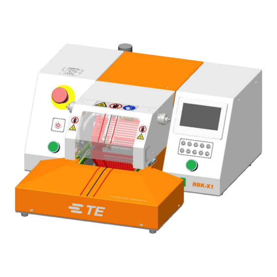
General Information Fig. 1-1: General View The RBK-X1C is a semi-automatic unit using an infrared process to heat shrink TE Connectivity ILS-125, ILS-85 and QSZH products onto ultrasonically welded or crimped splices. The equipment is designed to operate in conjunction with ultrasonic welders, positioned adjacent to the welding head. -
Page 7: Front Panel
RBK-X1C PN 2376800-1 Controls and Major Components Front Panel 14 Offset Knob 13 Distance Knob 6 Heater Chamber 1 Emergency Stop 7 Touch Screen 2 I/O Switch 8 Gripper 9 Process Button 3 Detection Plate 10 Calibration Socket 4 Cycle start... -
Page 8: Front Panel-Touch Screen
RBK-X1C PN 2376800-1 Front Panel-Touch Screen Fig. 1-3: Touch Screen ( main interface This picture above shows the main interface. For other interfaces, see section 3 software. 1. Heater Indicator (Illuminated amber when the heater starts to warm up. Illuminated green when the heater reaches the set value. Ready for production.) 2. -
Page 9: Rear Panel
(230V AC, 3A anti-surge) 10. Fan Fuse. (230V, 1A anti-surge) 11. Main Power Switch. (Used to turn ON/OFF power to RBK-X1C.) 12. Power Input Socket. (230V) 13. Main Power Fuse. (2 x 230V, 3.15A anti-surge) Do not use the Main Power Switch, or the Emergency Stop button on the front panel (see Figure 1-2), to turn off the machine, as this will cause a significant reduction to the life of the heater element. - Page 10 RBK-X1C PN 2376800-1 EMC Protection for connecting external devices to the RBK-X1C Processor. Connecting any external device to the following outputs below a ferrite core must be clamped to every connection used. The ferrite clamp must contain one loop. Connection for the following four items requires a ferrite clamp with one loop.
-
Page 11: Safety
RBK-X1C PN 2376800-1 Safety In common with all electrical equipment, the RBK-X1C must be used in accordance with established safe working practices. Prior to using the equipment, carefully read the Installation and Operating instructions (Section 3), together with the following safety warnings. -
Page 12: Electrical Safety
RBK-X1C PN 2376800-1 Electrical Safety The equipment is connected to an AC mains electricity supply. Before undertaking any maintenance or repair, always turn off the equipment and ensure it is isolated from the AC supply. Allow the equipment to cool. -
Page 13: Personal Safety
2.3.6 Servicing When carrying out repairs, always follow the instructions contained in this manual or contact TE Connectivity for further advice. Keep a record of the maintenance and servicing of the equipment. Do not use substitute components. Use only TE Connectivity approved parts. If the mains (utility) power supply cord is damaged, it must be replaced only by a special cord or assembly available from the supplier or its agent. -
Page 14: Warnings And Labels
RBK-X1C PN 2376800-1 Warnings and Labels The RBK-X1C carries a label (shown below) that displays the product part number (PCN), product description, and electrical rating information. The following icons are used in this manual: Information to prevent personal injury from electrical hazard. -
Page 15: Software
RBK-X1C PN 2376800-1 Software The software serves as the processor's central control unit. With this you can set the procedures for product processing. The software is operated via a touch screen. When the heater is powered on, the main interface is displayed as shown in this picture.. -
Page 16: Heat Parameter
RBK-X1C PN 2376800-1 Heat parameter In this interface, operator can pre-set/edit heat parameter (product size/heat temperature/heat time) stored in the 10X quick button. To edit the parameter stored in button (for example): 1. Switch , allow the operator to edit the parameter. -
Page 17: Sequence Production
RBK-X1C PN 2376800-1 Sequence production In this interface, processor entry the Sequence production mode. Click on this icon to select the Sequence number. 1#, for example. It would show the selected button, which originally stored in sequence 1# 5). -
Page 18: Sequence Setting
RBK-X1C PN 2376800-1 Sequence Setting In this interface, operator can pre-set/edit Sequence stored in the 15X Sequence. To edit the parameter stored in Sequence: 1. Switch , allow the operator to edit the parameter. 2. Click on this icon to select the Sequence to be edited. 1#, for example. -
Page 19: Production Setting
RBK-X1C PN 2376800-1 Production Setting Production quantity counter. The number here will +1 automatically after each cycle is completed. (The counter won’t count the cycle which was interrupted.) Operator can preset the production target (quantity) here. a. If you input the value, when processor complete the setting production quantity, on the main interface will pop up a tip “complete”, to remind the operator production is completed. -
Page 20: Maintenance
RBK-X1C PN 2376800-1 Maintenance Standby Time, the processor will automatically entry standby mode if no action. Default value: 60 mins, turn OFF this function by input value “0”. Processor Calibration Counter, by cycle (pc) or by Hour. Default value: 75000 pcs / 350 Hours. No matter which value met, calibration is required. -
Page 21: Auto Calibration
The following procedure describes how to calibrate the Processor, by comparing the expected UHI probe peak temperature with the actual UHI peak temperature recorded after a 15 second cycle. The RBK-X1C processor will automatically calculate the temperature Offset required to correct any errors and automatically replace the existing Offset value in the parameter memory. -
Page 22: Manual Calibration
RBK-X1C PN 2376800-1 Manual Calibration 1. Inactivate the “Centering” function in HMI Maintenance page. 2. Set tool to 500° C and 15 second cycle time. 3. Connect UHI probe to a calibrated meter. 4. Carry out 3 calibration readings (cool UHI to 23°C between each cycle). -
Page 23: Remote Operation Mode
RBK-X1C PN 2376800-1 Remote Operation Mode The remote operating mode allows the RBK-X1C to be controlled by external devices such as an industrial Computer or Ultrasonic Welding equipment. Remote operation is enabled via the RS232 connector, through an RS232 cable connecting to the external device. -
Page 24: Rs232 Data Format
The checksum hex (A-F) must be in ASCII lower case. The RBK-X1C Processor will ignore all RS232 data until a SOH character is recognized. On receipt of a SOH, 10 additional characters or an EOT character is sought. For each character received (including the SOH) the longitudinal addition (checksum) is maintained up to and including byte 11. -
Page 25: System Parameter
RBK-X1C PN 2376800-1 System Parameter Processor cycle counter. This value cannot be reset. It will record the total cycle after processor leave TE factory. Processor timer. This value cannot be reset. It will record the total operating hours after processor leave TE factory. -
Page 26: Error Log
RBK-X1C PN 2376800-1 3.10 Error Log This page will show error message on HMI. Other machine issue please find from section 4.3 Troubleshooting Error Possible Reason Action The machine isn't powered off in right process 1. Check the emergency stop button was pressed Power off! 1. -
Page 27: Circle Test
PN 2376800-1 3.11 Circle Test This is a testing interface, which was designed to test the RBK-X1C to run cycle in 500 C/0.2S for 60 min. So as to make sure machine work well before leaving factory. To start the circle test: 1. -
Page 28: Centering Manual
RBK-X1C PN 2376800-1 When heater in load position, this icon will illuminate green. When heater in home position, this icon will illuminate green. Press on this button, heater will move to forward to load position. Press on this button again, heater will move backward to home position. -
Page 29: Barcode Scanning
RBK-X1C PN 2376800-1 3.14 Barcode scanning Barcode scanning can help processor to get the product’s heating parameter (Temperature/time…) by reading the barcode attached on the product, then upload and change current heating parameter to processor accordingly. (1) Login on from main interface as User ID “C”, select BARCODE SCANNING to... -
Page 30: 3.15 Data Collection
RBK-X1C PN 2376800-1 3.15 Data Collection Data Collection is designed to implement the storage of production data, for example: scan ID, product info, temperature, time, date and so on. Production data could be stored to USB stick or external PC through using this feature. -
Page 31: Installation And Operation
Installation 4.1.1 Unpacking Remove the RBK-X1C from its packing. If there is any sign of damage, return the equipment to TE in its original container. Note: The Serial Number on machine must correspond with the Serial Number on the packaging. -
Page 32: Operation Mode
RBK-X1C PN 2376800-1 Operation mode 4.2.1 Stand-by mode When turn on the main power switch, the I/O button LED start to flash, machine is in stand-by, no power is connected to the heater, fan and motor circuits. Currently the machine is showing standby interface and ready to power ON by press on I/O button for 5 second. -
Page 33: Switch On/Off To Processor
RBK-X1C PN 2376800-1 4.2.6 Switch ON/OFF to processor OFF/ ON Fig. 4-1: Power ON/OFF Switch ON 1. Connect the power input socket with 230V (+/-10%) AC by power cord. 2. Release the Emergency Stop button. 3. Switch the Mains Switch to ON from rear panel Touch screen will power on and show the standby interface. -
Page 34: Single Process Operation
RBK-X1C PN 2376800-1 4.2.7 Single Process Operation Action of the Process Start buttons is inhibited until the heater LED has changed to green. Operation of any individual Start button during the timer count-down will manually override the process and move the heater chamber to the rear. -
Page 35: Auto Centering Operation
RBK-X1C PN 2376800-1 4.2.8 Auto Centering Operation Action of the Process Start buttons is inhibited until the heater LED has changed to green. Operation of any individual Start button during the timer count-down will manually override the process and move the heater chamber to the rear. -
Page 36: Emergency Stop
RBK-X1C PN 2376800-1 9. When the Timer reaches zero, the heater will move backward to home position, and the processed splice will be ejected. Cycle completed, DETECTION PLATE drops down, ready for next cycle. Note: TAKE CARE WHEN HANDLING THE EJECTED CABLE SPLICE AS IT WILL BE HOT. -
Page 37: Heater Carriage Jammed
RBK-X1C PN 2376800-1 4.2.10 Heater Carriage Jammed Heater Carriage Jams. Power to the motor and heater will remove automatically. The RBK processor heaters will switch off automatically if the carriage has not reached the front sensor in 700ms. Power to the drive motor removed. -
Page 38: Emergency Heater Chamber Release
RBK-X1C PN 2376800-1 4.2.11 Emergency Heater Chamber Release This is an EMERGENCY procedure used in the unlikely event of The Heater Chamber not opening when the Emergency stop is activated. The equipment is connected to an AC mains electricity supply. Before undertaking any maintenance or repair, always turn off the equipment and ensure it is isolated from the AC supply. -
Page 39: Routine Maintenance
4.2.12 Routine Maintenance The RBK-X1C requires only the minimum of maintenance. However, the following checks must be carried out on a weekly basis: 1. Check the cooling fan is operating correctly and air is flowing through the rear vent panel. -
Page 40: Troubleshooting
RBK-X1C PN 2376800-1 Troubleshooting THE TASKS IN THIS SECTION SHOULD ONLY BE CARRIED OUT BY A SUITABLY QUALIFIED TECHNICIAN. BEFORE STARTING ANY REPAIRS, THE MACHINE MUST BE DISCONNECTED FROM THE MAINS SUPPLY. AFTER COMPLETION, THE APPROPRIATE SAFETY CHECKS MUST BE MADE. - Page 41 RBK-X1C PN 2376800-1 Problem Possible Cause Verification Solution Heater chamber Heater not in rear Check heater chamber Remove obstruction. fails to move when position. position. Press cycle start start buttons Check for obstruction. buttons to return pressed. heater to the rear position.
- Page 42 RBK-X1C PN 2376800-1 Problem Possible Cause Verification Solution ‘Load’ proximity Check that the ‘Load’ Heating chamber moves forward Adjusting sensor and returns immediately to the sensor permanently sensor internal LED position. Replace Home position. 'OFF' or defective. sensor if necessary.
-
Page 43: Recommended Spare Parts
RBK-X1C PN 2376800-1 Recommended Spare Parts , how to remove the cover to replace below spare parts. Refer to section 4.5.2 Gaining Access Description Picture Part No Note Refer to section 1.2, Start button 2234980-1 item 3 Contact, Start button... - Page 44 RBK-X1C PN 2376800-1 Remove the Top Ejector blade, Left 2-2369603-2 Front cover to replace these Ejector blade, Right 2-2369603-3 Ejector blades Heating Element Assembly 2234991-1 See section 4.5.3 (including upper and lower how to replace the heater, thermocouple is part of heating element lower heater.)
- Page 45 RBK-X1C PN 2376800-1 Locate in Right Proximity Sensor 2234988-1 cover (Heater home/load position sensor) Switch 2234985-1 Locate in Right cover PLC Module 2234964-1 Locate in Right cover Safety Relay 2234967-1 Locate in Right cover 2234968-1 Locate in Left Cover Temperature controller...
- Page 46 RBK-X1C PN 2376800-1 Detection Plate, Left 3-2369602-1 Locate in Top Front cover Detection Plate, Right 6-2369602-5 Locate in Top Valve, centering plate 6-2369604-9 Middle cover Cylinder, Detection plate 6-2369604-7 Locate in Top Middle cover Cylinder, Centering plate 4-2369604-5 Locate in CD...
-
Page 47: Repair
RBK-X1C PN 2376800-1 Repair THE TASKS IN THIS SECTION SHOULD ONLY BE CARRIED OUT BY A SUITABLY QUALIFIED TECHNICIAN. THE MACHINE MUST BE ALLOWED TO COOL AND BE DISCONNECTED FROM THE MAINS SUPPLY BEFORE CARRYING OUT ANY REPAIR OR REPLACEMENT. -
Page 48: Gaining Access
RBK-X1C PN 2376800-1 4.5.2 Gaining Access To gain access to the internal components, the side and top covers must be removed. Use the correct size Key. Right cover Top Rear cover Left cover Top middle cover Top front cover L-side guard... - Page 49 RBK-X1C PN 2376800-1 Top Rear Cover Securing Screws (4X) Left Cover Securing Screws (7X) Right Cover Securing Screws (7X) Page 48 Rev. A Dec. 2020...
- Page 50 RBK-X1C PN 2376800-1 L-side guard (2X) and R-side guard (2X) securing screws CD cover Securing Screws (4X) Page 49 Rev. A Dec. 2020...
-
Page 51: Heater Element Replacement
RBK-X1C PN 2376800-1 4.5.3 Heater Element Replacement. ENSURE THAT MAINS SUPPLY IS DISCONNECTED. The two heater elements are mounted within a protective cage. Each are removed separately, but must be replaced as a set. REMOVE TOP GUARD FIRST. Replacement procedure 1. -
Page 52: Optional Accessories
RBK-X1C PN 2376800-1 OPTIONAL ACCESSORIES Below option components were not included in standard machine. Customer need to purchase from TE Please consult with product manager for PN on TBD item. separately IF NEED. 4.6.1 Calibration tools 288869-000 Standard UHI temperature calibration probe... -
Page 53: Fixture, 3 In 1
RBK-X1C PN 2376800-1 4.6.3 3 in 1 Fixture 2234786-1 3 in 1 fixture 2234786-2 3 in 1 fixture, with air cooling kit Note: This fixture can work for single/dual stub, single/dual wire product, single end product. 2234786-1 2234786-2 4.6.4 Air Cooled Stub splice fixture. -
Page 54: Specification
RBK-X1C PN 2376800-1 Specification RBK-X1C Electrical Supply 230V(+/-10%) - 50 Hz(+/-1Hz) ) Can connect to 110V via optional transformer 2234986-1 Pressure air Supply 4~6 bar Power Consumption 3 A (Maximum) Operating Temperature Range 200ºC to 600ºC Maximum (Acc. ± 1ºC of set temperature) 500°C Recommended... -
Page 55: Schematic Diagram
RBK-X1C PN 2376800-1 Schematic Diagram. Page 54 Rev. A Dec. 2020... - Page 56 RBK-X1C PN 2376800-1 Page 55 Rev. A Dec. 2020...
- Page 57 RBK-X1C PN 2376800-1 Page 56 Rev. A Dec. 2020...
- Page 58 RBK-X1C PN 2376800-1 Page 57 Rev. A Dec. 2020...
- Page 59 RBK-X1C PN 2376800-1 Page 58 Rev. A Dec. 2020...
- Page 60 RBK-X1C PN 2376800-1 Page 59 Rev. A Dec. 2020...
- Page 61 RBK-X1C PN 2376800-1 Page 60 Rev. A Dec. 2020...
- Page 62 RBK-X1C PN 2376800-1 Page 61 Rev. A Dec. 2020...
- Page 63 RBK-X1C PN 2376800-1 Page 62 Rev. A Dec. 2020...
-
Page 64: Pneumatic Diagram
RBK-X1C PN 2376800-1 Pneumatic Diagram Page 63 Rev. A Dec. 2020... -
Page 65: Address "After" Sales
RBK-X1C PN 2376800-1 Address "After" Sales. Tyco Electronics (Shanghai) Co., Ltd F/G/H Section, 1/F, Building 15, 999 Yinglun Road, (Shanghai) Pilot Free Trade Zone, China GATD Hotline: +86-021-33989030 Email: TEFE1AP@te.com Page 64 Rev. A Dec. 2020...
Need help?
Do you have a question about the RBK-X1C and is the answer not in the manual?
Questions and answers