Advertisement
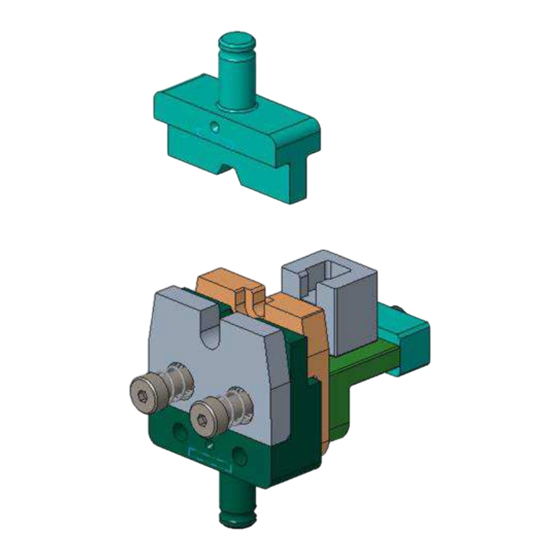
Figure 1: Crimping die and ferrule locator assembly for HVA HD400 ferrules
1
Introduction
The crimping die assembly (Figure 1) is designed to be installed into the modular tool holders listed in Table 1.
The crimping die assembly is designed to crimp HVA HD400 ferrules.
Crimping die
assembly
2374311-1
NOTE
Dimensions in this instruction sheet are in millimeters with [inches in brackets]. Figures are for reference only and are not
drawn to scale.
Read these instructions thoroughly before crimping ferrules.
© 2023 TE Connectivity Ltd. family of companies.
All Rights Reserved.
TE Connectivity, TE connectivity (logo), and TE (logo) are trademarks. Other logos, product, and/or company names may be trademarks of their respective owners.
Crimping Die and Ferrule Locator
Assembly for HVA HD400 Ferrules
Table 1: Crimping specifications
Wire size
Ferrule
mm²
part number
2371242-1
2.5
2371243-1
2371242-2
4
2371243-1
2371242-3
6
2371243-1
PRODUCT INFORMATION +1 800 522 6752
Application
Modular
specification
tool holders
2305470-1
114-160093
2326378-1
This controlled document is subject to change.
For latest revision and Regional Customer Service,
visit our website at www.te.com.
Instruction Sheet
408-35328
18 APR 2023 Rev A
1 of 7
Advertisement
Table of Contents

Subscribe to Our Youtube Channel
Related Manuals for TE Connectivity HVA HD400


Summary of Contents for TE Connectivity HVA HD400
- Page 1 1 of 7 For latest revision and Regional Customer Service, All Rights Reserved. visit our website at www.te.com. TE Connectivity, TE connectivity (logo), and TE (logo) are trademarks. Other logos, product, and/or company names may be trademarks of their respective owners.
- Page 2 408-35328 Description Each crimping die assembly consists of a crimper, a nest, a terminal stopper, a ferrule locator, and a ferrule locator assembly (Figure 2). NOTE The rear locator and the ferrule locator assembly maintain the ferrule position during the crimping process. They are supplied pre-assembled to the crimping die.
- Page 3 408-35328 Installing the die set and locator assembly For information concerning die installation, removal, and general performance of each modular tool holder, refer to the applicable 408 series instruction sheet packaged with the tool holder (Table 2). Table 2: Instruction sheets Modular tool holder Instruction sheet 2305470-1...
- Page 4 408-35328 Crimping For strip length and specific crimp information for each terminal being crimped using this die assembly, refer to the application specification listed in Table 1. CAUTION If the tool holder is equipped with a crimp height (fine adjust) adjustment, you can avoid damage to the terminator, modular tool holder, or die assembly by starting at setting A on the crimp disc and incrementally adjusting to the specified crimp height.
- Page 5 408-35328 4. Refer to Figure 5 and verify that: The outer ferrule butts against the ferrule locator. The crimped contact is inserted in the terminal block (stopper). The latch on the contact body is in the pocket of the terminal stopper. NOTE The crimped contact must fit within the identified surfaces to ensure proper spacing and orientation (see Figure 4).
- Page 6 408-35328 5. Close the wire clamp to hold the wire in place. 6. Cycle the terminator to complete the crimp. 7. Open the wire clamp to remove the crimped assembly from the tooling. Figure 6: Closing and opening the wire clamp Inspecting the crimp For crimp inspection information, refer to the 114 series application specification listed in Table 1 for the ferrule being crimped.
- Page 7 Call +1 800 522 6752. Write to: CUSTOMER SERVICE (038-035) TE CONNECTIVITY CORPORATION PO BOX 3608 HARRISBURG PA 17105-3608 For customer repair services, call +1 800 522 6752. Revision summary Since the last revision of this document, the following changes were made: ...
Need help?
Do you have a question about the HVA HD400 and is the answer not in the manual?
Questions and answers