EOS EMOTEC DC 9000 User Manual
Hide thumbs
Also See for EMOTEC DC 9000:
- Assembly and operating instructions manual (39 pages) ,
- User manual (24 pages)

Related Manuals for EOS EMOTEC DC 9000


Summary of Contents for EOS EMOTEC DC 9000
- Page 1 User‘s Guide EMOTEC DC 9000 Made in Germany IP x4 Druck Nr. 2934528en / -22.08...
-
Page 2: Table Of Contents
English Table of Contents Package contents ....................3 Technical data ......................3 General information concerning sauna bathing ............4 General safety precautions ..................5 Assembly of the control unit ..................6 Wall mounting ....................6 Electrical connection ..................7 Connecting the sauna oven ................7 Connecting the sauna lamp ................7 Connecting the sensor lines ................8 Mounting the oven sensor .................8 Operation ........................9... -
Page 3: Package Contents
Package contents (subject to change) Included with the control unit are: 1. An heater-sensor board with overheat shutoff protection, KTY-sensors with sensor hou- sing , two 3x25 mm fastening screws and a 1,7 m long sensor cable, red and white. 2. -
Page 4: General Information Concerning Sauna Bathing
General information concerning sauna bathing Dear customer, with purchase of this sauna control unit you For the cabin light use only light bulbs. Do opted for a superior quality, high-tech elec- not use fl uorescent lamps, energy saving tronic device which was developed and lamps and gas discharge lamps. -
Page 5: General Safety Precautions
General safety precautions • his device has not been designed for being • Please note the safety and installation in- used by persons (including children) that formation from the sauna oven manufac- are physically or mentally handicapped turer. or have sensory disabilities. Moreover, it •... -
Page 6: Assembly Of The Control Unit
Assembly of the control unit Wall mounting Mount the control unit outside the sauna cabin only. The most practical mounting point would be the wall area onto which the sauna oven is mounted on the inside, except on the outside of the cabin. If elec- trical conduits are present, mount the con- trol unit accordingly. -
Page 7: Electrical Connection
Electrical connection Connecting the sauna oven Assemble the sauna oven according to the The electrical connection instructions provided by the manufacturer only be done by a qualifi ed elec- in front of the air intake opening. trical technician under authority of the regulations of the local power supply Lead the silicon lines through the electrical company and those of the VDE. -
Page 8: Connecting The Sensor Lines
2. Drill a hole to lead the cable through, pre- Connecting the sensor lines ferably through the middle of one of the ou should not install sensor and power sup- wooden boards. ply lines together, or lead them through the 3. -
Page 9: Operation
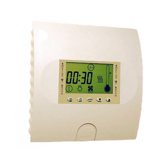
Operation Button functions Mode Lamp Program button Operating Selection switch on - off on - off buttons Symbol description Time Heating (dry) Preselected time Ventilation function Lamp Heating time Coloured light Error message If the control box does not pick off voltage after closure, please check the position of the control box switch (Switch-Off). -
Page 10: Switching On The Device For The First Time
Switching on the device for the fi rst time After checking all the connections once again, connect the device to the mains by switching on the fuses or mains switch. The time appears on the display. 20:03 If the display fl ashes, proceed as follows: 12:03 Please chose the wished value with the „... -
Page 11: Default Parameters
Default parameters Finnish sauna operation After switching on the screen displays the current time and remaining heating time 20:03 alternately. 05:58 Temperature indicator The temperature is indicated on the right side of the screen above the thermometer icon. Pre-selected Here the pre-selected temperature is temperature indicated by an arrow to the right of the thermometer. -
Page 12: Please Note The Following When Programming The Unit
The sauna switches off automatically at the end of the selected heating time. 20:03 If you want to end your sauna before this time, press the „ „ button. The sauna is switched off. The screen indicates the current time. Please note the following when programming the unit The buttons to be used are shown in the text as follows. -
Page 13: Specialist Section
Specialist section F1 Setting the current time For clock time adjustment please press „Mode“ and „ “ button synchron. (In the display appears „F1“ and the clock symbol.) Please confi rm with the „Mode“ button. 20:03 Please chose the wished value with the „... -
Page 14: P1 Start With Preset Time
Programming section Start with preset time You can use the time pre-selection to start your sauna within the next 24 hours. Always ensure that no objects are located on the sauna heater at the start of heating process. Risk of fi re! For the heating adjustment please press „Mode“button. -
Page 15: P2 Preset Time Mode
P2 Preset time mode The heating time limiter is fi xed at 6 hours. After these time the sauna will automatic shut-off. For the heating time limiter adjustment ple- ase press „Mode“ button. Afterwards the „ „ button until in the dis- play the the heating time symbol and „P2“... -
Page 16: P5 Temperature Setting
P5 Temperature setting Attention:Temperature range in Finnish operation 30-110 C in humidity operation 30-70 C The temperature is fi xed on 95C for Finnish operation and 60C for Humidity operation. For temperature adjustment please press „Mode“ button. Afterwards the „ „ button until in the display the heating symbol and „P5“... -
Page 17: P6 Programming Fan Operation
P6 Programming fan operation This control unit gives you the option of swit- ching on a fan (max. 100W) and setting the fan speed individually to one of 3 stages. The default setting is „no fan mode“. Only in post heating operation after operation humidity the fan is default on the maximum step. -
Page 18: P7 Ability To Dim The Cubicle Lights
P7 Ability to dim the cubicle lights Please note that this function may only be programmed in combination with incande- scent bulbs. No phosphorous, energy- saving or gas discharge bulbs may be used. The default light setting is maximum. You can dim the cubicle lighting of your sauna as you wish. -
Page 19: Coloured Light (Optional)
Coloured light (optional) This programming option is only available if the coloured light module (item number 942761) has been installed. Switch off all power to the system before installing the coloured light mo- dule. You have the option of operating a coloured light device in your sauna using the HCS 9003 control unit. - Page 20 If coloured light mode is to be switched off use the previous instructions and set the value to „0“. It goes without saying that the sauna lights can also be switched on and off in coloured light mode. To do so press the light switch as usual.
-
Page 21: P9 Setting The Time Interval For The Coloured Light
P9 Setting the time interval for the coloured light This programming option gives you the option of automatically setting the length of time each collour is on. The fefault is one minute. You can set on-time to between 1 and maximum 10 minutes.. For shining period adjustment please press „Mode“... -
Page 22: The Control Unit Switch (Switch-Off)
The control unit switch (Switch- C o n t r o l u n i t off) switch = unit swit- The control unit switch can be found on the ched on top end of the unit. Using this switch, you can isolate the electronics from the mains supply in case of a breakdown. -
Page 23: Error Display
Error display n order to provide an immediate diagnosis for any errors that may occur, the following errors can be determined via on-screen error codes. Error code Error E 100 Temperature sensor paused E 101 Temperature sensor short circuit E 211 Excess temperature fuse paused Other error options that are not displayed and their causes: Screen is blank –... -
Page 24: Connection Diagram
Connection diagram Attention! Dear customer, according to the valid regulations, the electrical connection of the sauna heater and the control box has to be carried out through the specialist of an authorized electric shop We would like to mention to the fact that in case of a warrenty claim, you are kindly requested to present a copy of the invoice of the executive electric shop. - Page 25 Service Address: Outside of Germany please contact your EOS-WERKE GÜNTHER GmbH specialist dealer in case of warranty claims. Adolf-Weiß-Straße 43 Direct warranty processing with our service 35759 Driedorf-Mademühlen, Germany department is in this case not possible.
-
Page 26: Handling Procedures For Return Shipments (Rma) - Details For All Returns
Handling procedures for return shipments (RMA) - Details for all returns ! Dear customer we hope that you will rejoice in the ordered articles. Just in case that you are not entirely contented as an exeption, please follow the procedures specified below.This enabling us to ensure a quick and smooth handling of the return shipment.
Need help?
Do you have a question about the EMOTEC DC 9000 and is the answer not in the manual?
Questions and answers