Beckhoff CP69 Series Manual
Hide thumbs
Also See for CP69 Series:
- Installation and operating instructions manual (28 pages) ,
- Manual (39 pages) ,
- Installation and operating instructions manual (24 pages)
Table of Contents
Advertisement
Quick Links
Advertisement
Chapters
Table of Contents

Related Manuals for Beckhoff CP69 Series


Summary of Contents for Beckhoff CP69 Series
- Page 1 Manual | EN CP69xx Control Panel 2024-03-20 | Version: 3.9...
-
Page 3: Table Of Contents
Table of contents Table of contents 1 Notes on the documentation........................ 5 2 For your safety ............................ 6 Signal words............................ 6 Intended use ............................. 6 Fundamental safety instructions ....................... 7 Operator's obligation to exercise diligence.................. 7 Notes on information security...................... 8 3 Product overview ............................ - Page 4 Table of contents Version: 3.9 CP69xx...
-
Page 5: Notes On The Documentation
EP1590927, EP1789857, EP1456722, EP2137893, DE102015105702 and similar applications and registrations in several other countries. ® EtherCAT is registered trademark and patented technology, licensed by Beckhoff Automation GmbH, Germany Copyright © Beckhoff Automation GmbH & Co. KG, Germany. The distribution and reproduction of this document as well as the use and communication of its contents without express authorization are prohibited. -
Page 6: For Your Safety
Exclusion of liability Beckhoff shall not be liable in the event of non-compliance with this documentation and thus the use of the devices outside the documented operating conditions. -
Page 7: Fundamental Safety Instructions
For your safety Fundamental safety instructions The following safety instructions must be observed when handling the device. Application conditions • Do not use the device under extreme environmental conditions. • Only use the device in hazardous areas if it is explicitly designed for this purpose. •... -
Page 8: Notes On Information Security
For your safety Notes on information security The products of Beckhoff Automation GmbH & Co. KG (Beckhoff), insofar as they can be accessed online, are equipped with security functions that support the secure operation of plants, systems, machines and networks. Despite the security functions, the creation, implementation and constant updating of a holistic security concept for the operation are necessary to protect the respective plant, system, machine and networks against cyber threats. -
Page 9: Product Overview
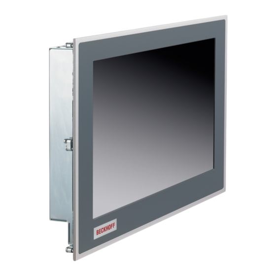
Product overview Product overview The single-touch built-in control panel is designed for control cabinet installation and is available in a wide range of diagonals. It can be used for a wide range of automation tasks. The control panel has the following features: •... -
Page 10: Structure
Product overview Structure Fig. 1: Structure Table 1: Key for CP69xx configuration Component Description Display and touch screen glass Operating the control panel Clamping lever Mounting the control panel in the control cabinet wall Grounding bolt Functional earth of the control panel Access to interfaces Interfaces on the underside Interface description... -
Page 11: Dvi Extended Input
Product overview 3.2.1 DVI Extended input The control panel has a DVI Extended input (X101). It is used to transmit the graphics signal from the industrial PC to the control panel. The graphics signal is transferred directly via a DVI cable over a distance of 50 m max. Such a cable length leads to strong distortion of the graphics signal on arrival at the control panel. -
Page 12: Usb Extended Input
Product overview 3.2.2 USB Extended input The control panel has a USB extended input (X102) in the form of an RJ45 socket. The interface is used to connect the control panel to the CU8801 USB-to-USB extended converter box. The interface transmits USB 2.0 with 480 Mbit/s. -
Page 13: Usb Output
The plug is included in the delivery. You can obtain a replacement plug from your Beckhoff Sales using the following ordering option: • C9900-P927: power supply connector for CP69xx Control Panel, 5-pin connector with strain relief for... -
Page 14: Status Leds
Product overview Status LEDs The control panel has six status LEDs. They are located on the rear side in the connection section of the panel (see fig. 8). Fig. 8: Status LEDs The LEDs have the following meanings: Table 7: LED functions Designation Meaning No function... -
Page 15: Name Plate
Product overview Name plate The name plate provides information about the control panel equipment. The name plate shown here serves only as an example. xxxxxxx Fig. 9: Name plate Table 8: Legend for CP69xx name plate Description Model: The last four digits indicate the device generation. Serial number (BTN) Date of manufacture Display... -
Page 16: Key Functions
Product overview Key functions You can order your Control Panel with different versions of the front laminate. You can choose between a panel without buttons and a panel with different button configurations. Please refer to the current price list for specific ordering options. - Page 17 Product overview Opening the properties window of a selected object Esc = close dialog box, cancel operations Set printed character to the cursor position … Function keys F1-F10 = functions of the keys determined by the software Special keys = Special keys with LED that can be determined by the automation software TwinCAT Einschub Einschub...
-
Page 18: Connection Kits
Product overview Connection kits The following optional connection kits are available: Table 10: CP69xx connection kits Connection kits Description C9900-K560 1 m connection kit for CP69xx, consisting of: DVI cable 1 m, USB cable 1 m C9900-K513 3 m connection kit for CP69xx, consisting of: DVI cable 3 m, USB cable 3 m C9900-K515 5 m connection kit for CP69xx, consisting of:... -
Page 19: Commissioning
You can either order a Beckhoff protective film individually and fit it yourself retrospectively, or you can order the film for fitting directly ex factory. Please refer to the price list for the available protective films according to the display size of your device. -
Page 20: Transport And Unpacking
4. Check your delivery for completeness by comparing it with your order. 5. Check the contents for visible shipping damage. 6. In case of discrepancies between the package contents and the order, or in case of transport damage, please inform Beckhoff Service (see Chapter 9.1 Service and Support). Version: 3.9 CP69xx... -
Page 21: Control Cabinet Installation
The device is designed for installation in the front of a control cabinet in machine and system engineering. The environmental conditions specified for operation must be observed. Dimensions The dimensions of the control panel can be found on the Beckhoff website: https://www.beckhoff.com/de- de/support/downloadfinder/technische-zeichnungen/. All dimensions are in mm. -
Page 22: Fig. 10 Delivery State Clamping Lever
Commissioning Fig. 10: Delivery state clamping lever To install and secure the control panel in the control cabinet, follow the steps shown in Fig. 11 and 12: 1. Insert the control panel at the intended position in the control cabinet wall. Make sure that the device is secured against falling out until it is fastened properly. -
Page 23: Fig. 12 Control Cabinet Installation
Commissioning Fig. 12: Control cabinet installation Also see about this 2 Technical data [} 33] CP69xx Version: 3.9... -
Page 24: Connecting The Control Panel
If you require a replacement for the voltage connector or the strain relief housing, you can order these from Beckhoff Sales using the following ordering option: • C9900-P927: power supply plug for CP69xx or CP66xx Control Panel, 5-pin connector with strain relief... -
Page 25: Fig. 13 Assembly Of Strain Relief Housing
Commissioning Fig. 13: Assembly of strain relief housing To remove the strain relief housing, proceed as follows: 1. Use your fingers to bend the latching lugs on the lower part slightly outwards (see Fig. 14). 2. Lever the upper part off the lower part. 3. -
Page 26: Grounding The Control Panel
Commissioning 4.3.2 Grounding the Control Panel Potential differences are minimized and electrical currents are diverted to the ground through grounding or potential equalization of electronic devices. This is to prevent dangerous touch voltages and electromagnetic interference. Protective earth The protective grounding of a device serves to avoid dangerous touch voltages. According to the EN 60204-1 standard (Chapter 8 Potential equalization), protective grounding is required if: •... -
Page 27: Connecting Cables And Power Supply
When connecting the control panel to an industrial PC with UPS output, Beckhoff recommends using this for the connection so that the display is also active in UPS mode. Only one control panel may be connected to the UPS output on the PC. -
Page 28: Decommissioning
Decommissioning Decommissioning NOTICE Hardware damage due to power supply A connected power supply can cause damage to the device during disassembly. • Disconnect the power supply from the device before starting to disassemble it. When taking the control panel out of operation, you must first disconnect the power supply and cables. You can then remove the device from the control cabinet. -
Page 29: Disassembly And Disposal
Decommissioning Disassembly and disposal In order to be able to dismount the control panel from the control cabinet, you must first have disconnected the power supply and the cables (see Chapter 5.1 Disconnecting the power supply and cables [} 28]). To remove the control panel from the control cabinet, follow the steps shown in Fig. 16 and 17: 1. -
Page 30: Maintenance
You can clean the front screen of the device during operation. In order to avoid inadvertent touch entries when doing this, you must first set the device to "Cleaning Mode" with the help of the Beckhoff Control Tool. The Beckhoff Control Tool does not start automatically when the device starts up. Proceed as follows to activate the "Cleaning Mode"... -
Page 31: Fig. 18 Select "Cleaning Mode
5 and 120 seconds. Right-click the sun symbol again and click "Options". Now select the appropriate duration (see Fig.). Fig. 19: Configuration "Cleaning Mode" Repair Only the vendor may repair the device. If a repair should be necessary, contact Beckhoff Service (see Chapter 9.1 Service and Support [} 34]). CP69xx Version: 3.9... -
Page 32: Troubleshooting
Measures No control panel function Lack of power supply to the control Check the power supply cable panel Call Beckhoff Service Other cause The control panel only works Defective backlight in the display Call Beckhoff Service partially or only temporarily (e.g. -
Page 33: Technical Data
(24 V power supply unit, NEC class 2) Power consumption Data sheet for calculating power consumption and power loss in the download finder - Data sheets: http://www.beckhoff.com/downloadfinder Protection rating Front IP65, rear IP20 Vibration resistance (sinusoidal EN 60068-2-6: 10 to 58 Hz: 0.035 mm... -
Page 34: Appendix
33415 Verl Germany Phone: + 49 5246/963-0 email: info@beckhoff.de The addresses of the worldwide Beckhoff branches and agencies can be found on our website at http:// www.beckhoff.com/. You will also find further documentation for Beckhoff components there. Version: 3.9 CP69xx... -
Page 35: Approvals
Appendix Approvals Your device has at least the following approvals: • CE • EAC • UKCA • FCC You will find all other applicable approvals on the name plate of your device. FCC approvals for the United States of America FCC: Federal Communications Commission Radio Frequency Interference Statement This device was tested and complies with the limits for a digital device of class A, according part 15 of the FCC regulations. - Page 36 List of figures List of figures Fig. 1 Structure............................Fig. 2 Connection section........................Fig. 3 DVI-E input pin numbering ......................Fig. 4 USB-E input pin numbering......................Fig. 5 USB input pin numbering ......................Fig. 6 USB output pin numbering ......................Fig.
- Page 37 List of tables List of tables Table 1 Key for CP69xx configuration....................... Table 2 DVI Extended interface pin assignment ..................Table 3 USB-E input pin assignment ......................Table 4 USB interface pin assignment...................... Table 5 USB interface pin assignment...................... Table 6 Voltage socket pin assignment ....................Table 7 LED functions..........................
- Page 39 More Information: www.beckhoff.com/cp69xx Beckhoff Automation GmbH & Co. KG Hülshorstweg 20 33415 Verl Germany Phone: +49 5246 9630 info@beckhoff.com www.beckhoff.com...
Need help?
Do you have a question about the CP69 Series and is the answer not in the manual?
Questions and answers