
Related Manuals for Beckhoff CP6909


Summary of Contents for Beckhoff CP6909
- Page 1 Installation and Operating instructions for Built-in Control Panel CP69xx Version: 2.3 Date: 2012-11-27...
-
Page 2: Table Of Contents
Functional description Operation Setting the transmission rate Keyboard codes Servicing and maintenance Cleaning the Control Panel Servicing Emergency procedures Shutting down Disposal Troubleshooting Fault correction Beckhoff Support & Service Beckhoff branches and partner companies Beckhoff Headquarters Beckhoff Support Beckhoff Service CP69xx... - Page 3 Table of contents Appendix Assembly dimensions Technical data Approvals FCC: Federal Communications Commission Radio Frequency Interference Statement FCC: Canadian Notice CP69xx...
-
Page 4: Foreword
Modifications to hardware or software configurations other than those described in the documentation are not permitted, and nullify the liability of Beckhoff Automation GmbH. Delivery conditions In addition, the general delivery conditions of the company Beckhoff Automation GmbH apply. -
Page 5: Description Of Safety Symbols
Foreword Description of safety symbols The following safety symbols are used in this operating manual. They are intended to alert the reader to the associated safety instructions. Acute risk of injury!! If you do not adhere the safety advise adjoining this symbol, there is DANGER immediate danger to life and health of individuals! Risk of injury! -
Page 6: Basic Safety Measures
Foreword Basic safety measures Only switch the PC off after Before the Industrial PC is switched off, software that is running must closing the software be properly closed. Otherwise it is possible that data on the storage medium is lost. Please read the section Functional description. -
Page 7: Operator's Obligation To Exercise Diligence
The operator must initiate such inspections in good time. Do not open the housing of the Control Panel! For technical support contact Beckhoff Service. Note Procedure in the event of a... -
Page 8: Product Description
Product Description Product Description Appropriate Use The CP69xx Control Panel is designed for industrial application in machine and plant engineering. A steel plate housing with aluminum front contains a TFT display, touch screen/ pad (optional) and a PC keyboard (optional). The Control Panel is installed in the front of control cabinets. -
Page 9: Connector Description
Product Description X106 Function Power Socket 5-pol RM3.50 Sw Screw Clamp BL3.5/180F (WEIDMÜLLER 1615810000) 24 V Power Supply Connector description DVI (Digital Visual Interface) X101 The DVI connection is used for transferring the video signal from the DVI in Industrial PC to the Control Panel. The purely digital part (DVI-D) is supported. -
Page 10: Control Panel Connecting Kits
Product Description Control Panel Connecting Kits Cable Set C9900-K513 Connecting kit 3 m for CP69xx, containing: 3 m DVI cable, 3 m USB cable C9900-K515 Connecting kit 5 m for CP69xx, containing: 5 m DVI cable, 5 m USB cable C9900-K421 Connecting kit 10 m for CP69xx including: 10 m DVI cable, 10 m CAT 5 cable for USB-E, USB to USB-E converter CU8800 for... -
Page 11: Installation Instructions
4. Please keep the associated paperwork. It contains important information for handling the unit. 5. Check the contents for visible shipping damage. 6. If you notice any shipping damage or inconsistencies between the contents and your order, you should notify Beckhoff Service. CP69xx... -
Page 12: Installation In The Control Cabinet
Installation Instructions Installation in the control cabinet The Control Panel CP69xx is designed for mounting in control cabinets in machine and plant engineering applications. The ambient conditions specified for operation must be observed (see chapter Technical data). Preparation of the control The control cabinet wall must be prepared with the required mounting cabinet opening for the computer unit according to the Control Panel’s dimensions... -
Page 13: Mounting Of The Control Panel
Installation Instructions Mounting of the Control Panel Please refer to the chapter Assembly dimensions for Control Panel cutout dimensions. Similar pictures. Mounting of the Control Panel with clamping levers Clamping levers Release clamping levers, Insert the Control Panel into the cutout. -
Page 14: Fitting The Cable
Installation Instructions Fitting the cable Wiring Fit the cables for the power supply of the Control Panel, using the included material for assembling the connectors. Material for assembling the connectors Material for assembling the connectors Plug connector 5-pole Stain relief housing with lacing cord Assembling the connectors Conductive cross-section The connector is specified for 16 A and can lift conductive cross-sections... -
Page 15: Connecting The Control Panel
Installation Instructions Connecting the Control Panel Risk of explosion! The Control Panel must never be connected or disconnected in an area DANGER that is subject to explosion hazard! Risk of explosion! Power supply plug The mains plug must be disconnected! Attention Please read the documentation for the external devices prior to connecting them. -
Page 16: Operating Instructions
Operating Instructions Operating Instructions Please also refer to chapter Foreword. Functional description Switch on The Control Panel does not have its own mains power switch. As soon as the power supply is switched on the control panel is activated. Shutting down and When the plant is switched off, or when it is disconnected from its power switching off supply, the Control Panel will be switched off. -
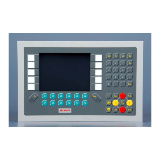
Page 17: Keyboard Codes
Operating Instructions Keyboard codes Type-dependent number of Depending on the precise type, the Control Panel can have fewer keys keys than those described here. Operation The cursor is the blinking character that marks the point at which the next character entered will be displayed. The cursor is also known as the insertion point. - Page 18 Operating Instructions The meaning of the function keys, F1 to F10, is determined by the software and is displayed at the bottom edge of the display. The function of the special keys above the display is also determined by Einschub Einschub Einschub Einschub...
-
Page 19: Servicing And Maintenance
Servicing The Control Panel requires no maintenance. Do not open the housing of the Control Panel! For technical support contact Beckhoff Service. Note Emergency procedures In case of fire, the Control Panel should be extinguished with powder or nitrogen. -
Page 20: Troubleshooting
Check power supply cable function when the Industrial PC has been started Cable not connected 1. Correctly connect cable 2. Call Beckhoff Service The Industrial PC does not boot Setup settings are incorrect Check the setup settings fully Other cause... -
Page 21: Beckhoff Support & Service
Please contact your Beckhoff branch office or partner company for local support and service on Beckhoff products! The contact addresses for your country can be found in the list of Beckhoff branches and partner companies: www.beckhoff.com You will also find further documentation for Beckhoff components there. - Page 22 Appendix Appendix Assembly dimensions Notice mounting orientation The assembly of the unit must take place with the orientation diagrammed Attention here. All dimensions are in mm. Control Panel CP6907 with 5,7“ display front view rear view with cutout dimensions side view rear view CP69xx...
- Page 23 Appendix Notice mounting orientation The assembly of the unit must take place with the orientation diagrammed Attention here. All dimensions are in mm. Control Panel CP69xx Dimensions CP690x CP6909 6.5"-Display 26.6 30.5 CP6901 12"-Display 24.6 32.5 CP6902 15"-Display 41.2 CP6903 19"-Display...
- Page 24 Appendix Technical data Dimensions Dimensions (W x H x D): see section Assembly dimensions. Operation in areas that are The Control Panel must not be used where there is a risk of subject to explosion hazard explosion. The following conditions must be observed during operation: Environmental conditions Ambient temperature: 0 to 55°C...
Need help?
Do you have a question about the CP6909 and is the answer not in the manual?
Questions and answers