
Related Manuals for Beckhoff CPX29 0000 Series


Summary of Contents for Beckhoff CPX29 0000 Series
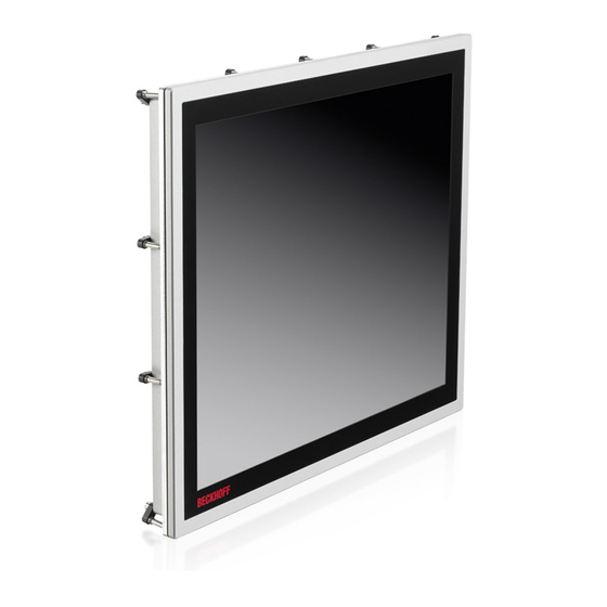
- Page 1 Installation and operating instructions | EN CPX29xx-0000 Multi-touch Control Panel with DVI/USB Extended interface for use in haz- ardous locations, zone 2/22 4/20/2021 | Version: 0.2...
-
Page 3: Table Of Contents
Table of Contents Table of Contents 1 Notes on the documentation ........................ 5 Explanation of symbols........................ 6 Documentation issue status ...................... 7 2 For your safety............................ 8 Intended use ............................ 8 Notes about operation in potentially explosive areas ................ 9 2.2.1 Special conditions (ATEX) .................... 9 2.2.2 Special conditions (IECEx) .................... - Page 4 Table of Contents 10.2 Connection Kits/ Connection Cables/Accessories................ 35 10.3 Approvals for USA and Canada ...................... 36 10.4 Support and Service ........................ 37 Version: 0.2 CPX29xx-0000...
-
Page 5: Notes On The Documentation
EP0851348, US6167425 with corresponding applications or registrations in various other countries. ® EtherCAT is registered trademark and patented technology, licensed by Beckhoff Automation GmbH, Germany Copyright © Beckhoff Automation GmbH & Co. KG, Germany. The reproduction, distribution and utilization of this document as well as the communication of its contents to others without express authorization are prohibited. -
Page 6: Explanation Of Symbols
Notes on the documentation Explanation of symbols The following symbols with corresponding warnings or explanatory text are used in the documentation. Read and follow the warnings. Symbols that warn of personal injury: DANGER Serious risk of injury Note this warning. Hazard with high risk of death or serious injury. WARNING Risk of injury Note this warning. -
Page 7: Documentation Issue Status
Notes on the documentation Documentation issue status Version Comment Preliminary Version CPX29xx-0000 Version: 0.2... -
Page 8: For Your Safety
Beckhoff Automation GmbH & Co. In addition, the following actions are excluded from the liability of Beckhoff Automation GmbH & Co. KG: • Failure to comply with this documentation. -
Page 9: Notes About Operation In Potentially Explosive Areas
For your safety Notes about operation in potentially explosive areas 2.2.1 Special conditions (ATEX) WARNING Danger of explosion Gases or dusts can be ignited in potentially explosive areas. Read and follow the safety instructions to pre- vent deflagration or explosions. The Control Panel must be installed in a housing, which ensures protection class IP54 for gas according to EN 60079-7. -
Page 10: Marking
For your safety 2.2.3 Marking The Control Panel CPX29xx-0000 bears a continuous serial number, markings and a production date on the name plate. xxxxxxxx Fig. 1: Name plate on the back side of the Control Panel CPX29xx-0000. The Control Panel CPX29xx-0000 is certified for potentially explosive areas and bears the following markings: ATEX: BVS 17 ATEX E 119 X Ta: 0..55°C... -
Page 11: Safety Instructions
• The sensitivity of an Industrial PC against malicious software increases with the number of installed and active software. • Uninstall or disable unnecessary software. Further information about the safe handling of networks and software can be found in the Beckhoff Information System: http://infosys.beckhoff.com... -
Page 12: Staff Qualification
For your safety Staff qualification All operations involving Beckhoff software and hardware may only be carried out by qualified personnel with knowledge of control and automation engineering. The qualified personnel must have knowledge of the administration of the Control Panel and the associated network. -
Page 13: Transport And Storage
4. Please keep the associated paperwork. It contains important information for handling the unit. 5. Check the contents for visible shipping damage. If you notice any shipping damage or inconsistencies between the contents and your order, you should notify Beckhoff Service. CPX29xx-0000 Version: 0.2... -
Page 14: Product Overview
--- FEHLENDER LINK --- control cabinet wall. The new Beckhoff panel generation with industry-standard multi-touch display offers a solution for any application. The control panel is also suitable for hazardous locations of Zone 2/22. The wide selection of models offers different display sizes and formats. Even for single-touch users, this new panel generation offers an excellent price- to-performance ratio and represents an economical alternative to other systems. -
Page 15: Access To The Interfaces
Product overview Access to the interfaces The interfaces of the Control Panel are located at the rear side of the housing. Fig. 3: Connection block of the Control Panel CPX29xx-0000 with all interfaces. CPX29xx-0000 Version: 0.2... -
Page 16: Name Plate
Product overview Name plate The Control Panel CPX29xx-0000 bears a continuous serial number, markings and a production date on the name plate. xxxxxxxx Fig. 4: Name plate on the back side of the Control Panel CPX29xx-0000. The Control Panel CPX29xx-0000 is certified for potentially explosive areas and bears the following markings: ATEX: BVS 17 ATEX E 119 X Ta: 0..55°C... -
Page 17: Description Of The Interfaces
Product overview Description of the interfaces Fig. 5: Interfaces of the Control Panel CPX29xx-0000. Interface Interface DVI-D In (X106) [} 18] USB out (X102, X103) [} 17] USB-E In (X105) [} 18] Ground [} 19] USB In (X104) [} 18] Power supply (X101) [} 17] Mounting bracket (see: Using the mounting bracket [} 25]) 4.3.1 Power supply (X101) X101... -
Page 18: Usb In (X104)
Product overview 4.3.3 USB In (X104) X104 USB type B, PCB installation (FCI 61729-0010B USB Receptacle B-Type) The Control Panel is connected with the Industrial PC via the USB port (X 104, connector type B). USB3.0 standard is supported. Signal Signal 4.3.4 USB-E In (X105) -
Page 19: Ground
Product overview 4.3.6 Ground Malfunction possible with missing ground connection A proper ground connection of the device is absolutely necessary for the correct function of the touchscreen. The Control Panel is grounded via the screw connection (Ground). A wire cross-section of min. 4 mm is required. -
Page 20: Mounting And Wiring
Mounting and wiring Mounting and wiring Mounting The Control Panel CPX29xx is designed for mounting in control cabinets in machine and plant engineering applications. The ambient conditions specified for operation must be observed (see chapter: Technical Data [} 32]). Permitted mounting position The Control Panel may only be mounted horizontally. - Page 21 Mounting and wiring Earthing measures Earthing connections dissipate interference from external power supply cables, signal cables or cables to peripheral equipment. Establish a low-impedance connection from the earthing point on the Control Panel housing to the central earthing point on the control cabinet wall, in which the Panel is being installed. Malfunction possible with missing ground connection A proper ground connection of the device is absolutely necessary for the correct function of the touchscreen.
-
Page 22: Mounting Of The Control Panel
Mounting and wiring 5.1.2 Mounting of the Control Panel The Control Panel is installed in the cabinet wall with clamping levers. You need to cutout the cabinet wall for the Control Panel. For the cutout dimensions of the Control Panel see chapter: Assembly dimensions [} 29]. The Control Panel may only be mounted horizontally. -
Page 23: Wiring
Mounting and wiring Wiring 5.2.1 Preperation and protective earthing NOTE The mains plug must be disconnected Please read the documentation for the external devices prior to connecting them! During thunderstorms, plug connector must neither be inserted nor removed! when disconnecting a plug connector, always handle it at the plug. -
Page 24: Fitting The Power Supply Cable
Mounting and wiring 5.2.2 Fitting the power supply cable Conductive cross-section The connector is specified for 10 A and can lift conductive cross-sections until 1.5 mm Fit the cables for the power supply of the Control Panel, using the included material for assembling the connectors: Material for assembling the connector... -
Page 25: Using The Mounting Bracket
Mounting and wiring 5.2.3 Using the mounting bracket In potentially explosive areas the USB plugs must not slip out of the interfaces. Fix the USB cables with cable straps to the mounting bracket. Requirements: • Cable straps. • Nipper or a side cutter. Proceed as follows: 1. -
Page 26: Operation
Operation Operation Switching the Control Panel on and off Switching on The Control Panel does not have its own mains power switch. As soon as the power supply is switched on the Control Panel is activated. Shutting down and switching off Control software such as is typically used on Industrial PCs permits various users to be given different rights. -
Page 27: Servicing And Maintenance
Maintenance The Control Panel is maintenance-free. Do not open the Control Panel. For hardware problems, please contact the Beckhoff Service Emergency procedures In case of fire, the Control Panel should be extinguished with powder or nitrogen. -
Page 28: Troubleshooting
The Control Panel shows no function No power supply to the Control Check power supply cable Panel/ Industrial PC 1. Correctly connect cable 2. Call Beckhoff Service Cable not connected Computer boots, software starts, but Cause of the fault is either in the... -
Page 29: Assembly Dimensions
Assembly dimensions Assembly dimensions CPX2915-0000 CPX29xx-0000 Version: 0.2... - Page 30 Assembly dimensions CPX2919-0000 Version: 0.2 CPX29xx-0000...
- Page 31 Assembly dimensions CPX2921-0000 CPX29xx-0000 Version: 0.2...
-
Page 32: Technical Data
Technical Data Technical Data Product name CPX2915-0000 CPX2919-0000 CPX2921-0000 Dimensions (W x H x D) 368.2 x 295.3 x 58 mm 438,3 x 369 x 58 mm 543 x 334.7 x 58 mm Weight approx. 3.7 kg approx. 5.4 kg approx. -
Page 33: Appendix
Appendix Appendix 10.1 Standards reference for explosive atmospheres The following standards have been used: ATEX Standard Description EN 60079-0:2012+A11:2013 Explosive atmospheres - Part 0: Equipment - General requirements EN 60079-7:2015 Explosive atmospheres - Part 7: Equipment protection by increased safety "e" EN 60079-31:2014 Explosive atmospheres - Part 31: Equipment dust ignition protection by enclosure "t"... - Page 34 Appendix cFMus Standard Description FM Class 3600:2018 Electrical Equipment for Use in Hazardous (Classified) Locations – General Requirements FM Class 3611:2018 Nonincendive electrical equipment for use in Class I and II, Division 2 and Class III, Divisions 1 and 2 hazardous (classified) locations FM Class 3810:2018 Electrical Equipment for Measurement, Control and...
- Page 35 Appendix 10.2 Connection Kits/ Connection Cables/Accessories One 5-pole power supply connector is provided with the Control Panel. Optionally prefabricated connection kits for the DVI-D/ USB-E connection are available. The following connection kits are available: Table 2: Connection Kits DVI-D/ USB-E connection for CPX29xx-0000, optional Connecting kit DVI-E/ USB-E Connection C9900-K622...
- Page 36 Appendix 10.3 Approvals for USA and Canada FCC: Federal Communications Commission Radio Frequency Interference Statement This equipment has been tested and found to comply with the limits for a Class A digital device, pursuant to Part 15 of the FCC Rules. These limits are designed to provide reasonable protection against harmful interference when the equipment is operated in a commercial environment.
- Page 37 Beckhoff's branch offices and representatives Please contact your Beckhoff branch office or representative for local support and service on Beckhoff products! The addresses of Beckhoff's branch offices and representatives round the world can be found on her internet pages: http://www.beckhoff.com You will also find further documentation for Beckhoff components there.
- Page 39 Beckhoff Automation GmbH & Co. KG Hülshorstweg 20 33415 Verl Germany Phone: +49 5246 9630 info@beckhoff.com www.beckhoff.com...
Need help?
Do you have a question about the CPX29 0000 Series and is the answer not in the manual?
Questions and answers