
Related Manuals for Beckhoff CP66 Series


Summary of Contents for Beckhoff CP66 Series
- Page 1 Installation and Operating instructions for Built-in Control Panel CP66xx Version: 1.3 Date: 2009-12-04...
-
Page 3: Table Of Contents
Replacing the battery on the motherboard Servicing Emergency procedures Shutting down Disposal Troubleshooting Fault correction Beckhoff Support & Service Beckhoff branches and partner companies Beckhoff Headquarters Beckhoff Support Beckhoff Service Appendix Technical data Approvals FCC: Federal Communications Commission Radio Frequency Interference... -
Page 4: General Notes
© This documentation is protected by copyright. Any reproduction or third party use of this publication, whether in whole or in part, without the written permission of Beckhoff Automation GmbH, is forbidden. Description of safety symbols The following safety symbols are used in this operating manual. They are intended to alert the reader to the associated safety instructions. -
Page 5: Basic Safety Measures
General Notes Basic safety measures Switch off all parts of the equipment, then uncouple the fieldbus Before opening the control panel housing, and whenever the control panel is not being used for control purposes (such as during functional checks Attention after a repair), all parts of the equipment must first be switched off, after which the control panel is to be disconnected from the equipment. -
Page 6: Operator's Obligation To Exercise Diligence
General Notes Operator's obligation to exercise diligence The operator must ensure that • the Control Panel is only used for its intended purpose (see Product Description section); • the Control Panel is only operated in a sound condition and in working order;... -
Page 7: Product Description
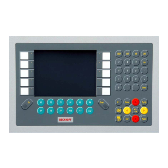
Product Description Product Description Appropriate Use The CP66xx Control Panel is designed for industrial application in machine and plant engineering. A steel plate housing with aluminum front contains a TFT display, touch screen/ pad (optional) and a PC keyboard (optional). The Control Panel is installed in the front of control cabinets. -
Page 8: Connector Description
Product Description X107 Function Power Socket 5-pol RM3.50 Sw Screw Clamp BL3.5/180F (WEIDMÜLLER 1615810000) 24 V DC Power Supply Connector description Serial interface X102 The Control Panel is equipped with a COM1 (X 102) serial interface (Type Serial interface COM1 RS232) for the connection of serial peripheral devices. -
Page 9: Installation Instructions
4. Please keep the associated paperwork. It contains important information for handling the unit. 5. Check the contents for visible shipping damage. 6. If you notice any shipping damage or inconsistencies between the contents and your order, you should notify Beckhoff Service. CP66xx... -
Page 10: Assembly
Installation Instructions Assembly Assembly dimensions Notice mounting orientation The assembly of the unit must take place with the orientation diagrammed Attention here. All dimensions are in mm. Control Panel CP6607 with 5,7“ display rear view with front view cutout dimensions side view rear view CP66xx... - Page 11 Installation Instructions Notice mounting orientation The assembly of the unit must take place with the orientation diagrammed Attention here. Control Panel CP66xx All dimensions are in mm. buttom view side view rear view Dimensions CP660x CP6609 6,5“-Display CP6601 12“-Display CP6602 15“-Display CP6603 19“-Display...
-
Page 12: Mounting Of The Control Panel
Installation Instructions Mounting of the Control Panel Please refer to the tables for Control Panel cutout dimensions. Mounting of the Control Panel Clamping levers Release clamping levers, Insert the Control Panel into the cutout. Release the clamping levers with a No. -
Page 13: Fitting The Cable
Installation Instructions Fitting the cable Wiring Fit the cables for the power supply of the Industrial PC, using the included material for assembling the connectors. Material for assembling the connectors Material for assembling the connectors Plug connector 5-pole Stain relief housing with lacing cord Assembling the connectors The connector is specified for 16 A and can lift conductive cross-sections Conductive cross-section... -
Page 14: Connecting The Control Panel
Installation Instructions Connecting the Control Panel Risk of explosion! The Control Panel must never be connected or disconnected in an area DANGER that is subject to explosion hazard! Mains plug The mains plug of the Control Panel must be disconnected! Attention Please read the documentation for the external devices prior to connecting them. -
Page 15: Operating Instructions
Operating Instructions Operating Instructions Please also refer to chapter General Notes. Functional description Switch on The Control Panel does not have its own mains power switch. As soon as the power supply is switched on the control panel is activated. Switching off Control software, as typically applied in Control Panels, enables the assignment of different rights to all users. -
Page 16: Keyboard Codes
Operating Instructions Keyboard codes Type-dependent number of Depending on the precise type, the Control Panel can have fewer keys keys than those described here. Operation The cursor is the blinking character that marks the point at which the next character entered will be displayed. The cursor is also known as the insertion point. - Page 17 Operating Instructions All other keys bring the character printed on them onto the display at the position of the cursor. The meaning of the function keys, F1 to F10, is determined by the software and is displayed at the bottom edge of the display. The function of the special keys above the display is also determined by Einschub Einschub...
-
Page 18: Servicing And Maintenance
Servicing The Control Panel is maintenance-free. Do not open the housing of the Control Panel For technical support contact Beckhoff Service. Note Emergency procedures In case of fire, the control panel should be extinguished with powder or nitrogen. -
Page 19: Troubleshooting
Check power supply cable function when the Industrial PC has been started Cable not connected 1. Correctly connect cable 2. Call Beckhoff Service The Industrial PC does not boot Hard disk damaged (e.g. by 1. Boot with boot diskette fully switching off while software running) 2. -
Page 20: Beckhoff Support & Service
Please contact your Beckhoff branch office or partner company for local support and service on Beckhoff products! The contact addresses for your country can be found in the list of Beckhoff branches and partner companies: www.beckhoff.com You will also find further documentation for Beckhoff components there. -
Page 21: Appendix
Appendix Appendix Technical data Dimensions Dimensions (W x H x D): see section Assembly dimensions. Operation in areas that are The Control Panel must not be used where there is a risk of subject to explosion hazard explosion. The following conditions must be observed during operation: Environmental conditions Ambient temperature: 0 to 55°C...
Need help?
Do you have a question about the CP66 Series and is the answer not in the manual?
Questions and answers