Beckhoff CP69 Series Installation And Operating Instructions Manual
Built-in control panel with dvi/ usb extended interface
Hide thumbs
Also See for CP69 Series:
- Manual (39 pages) ,
- Installation and operating instructions manual (24 pages) ,
- Manual (39 pages)

Subscribe to Our Youtube Channel
Related Manuals for Beckhoff CP69 Series


Summary of Contents for Beckhoff CP69 Series
- Page 1 Installation and Operating instructions for CP69xx Built-in Control Panel with DVI/ USB Extended interface Version: 2.5 Date: 2019-05-31...
-
Page 3: Table Of Contents
Table of contents Table of contents 1 Foreword Notes on the Documentation 1.1.1 Liability Conditions 1.1.2 Trademarks 1.1.3 Patent Pending 1.1.4 Copyright 1.1.5 State at Delivery 1.1.6 Delivery conditions Description of safety symbols Basic safety measures Operator’s obligation to exercise diligence 1.4.1 National regulations 1.4.2... - Page 4 6 Troubleshooting 7 Assembly dimensions 8 Technical Data 9 Appendix Beckhoff Support and Service 9.1.1 Beckhoff branches and partner companies 9.1.2 Beckhoff company headquarters Approvals for USA and Canada FCC Approvals for the United States of America FCC Approval for Canada...
-
Page 5: Foreword
Modifications to hardware or software configurations other than those described in the documentation are not permitted, and nullify the liability of Beckhoff Automation GmbH & Co. KG. 1.1.6 Delivery conditions In addition, the general delivery conditions of the company Beckhoff Automation GmbH & Co. KG apply. CP69xx... -
Page 6: Description Of Safety Symbols
Foreword 1.2 Description of safety symbols The following safety symbols are used in this operating manual. They are intended to alert the reader to the associated safety instructions. Acute risk of injury! If you do not adhere the safety advise adjoining this symbol, there is immediate danger to life and health of individuals! DANGER Risk of injury! -
Page 7: Basic Safety Measures
Foreword 1.3 Basic safety measures Before the Industrial PC is switched off, software that is running must be properly closed. Otherwise it is possible that data on the storage medium is lost. Please read the section Switching the Control Panel on and off. -
Page 8: Operator's Obligation To Exercise Diligence
• the operation manual is in good condition and complete, and always available for reference at the location of the product. Do not open the housing of the Control Panel! For technical support contact Beckhoff Service. Note 1.4.1 National regulations Depending on the type of machine and plant in which the Control Panel is used, national regulations governing the controllers of such machines will apply, and must be observed by the operator. -
Page 9: Product Description
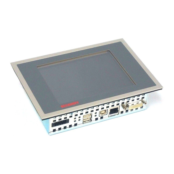
Product Description 2 Product Description 2.1 Product overview Front view of CP69xx The “Economy” built-in Control Panel offer the following benefits: • TFT display in different sizes • aluminium front with sheet-steel rear cover, front side IP65, rear side IP20 •... -
Page 10: Appropriate Use
Product Description 2.2 Appropriate Use The CP69xx Control Panel is designed for industrial application in machine and plant engineering. A steel plate housing with aluminum front contains a TFT display, touch screen/ pad (optional) and a PC keyboard (optional). The Control Panel is installed in the front of control cabinets. Risk of explosion! The Control Panel must not be used where there is a risk of explosion. -
Page 11: Usb-Extended Input (X 102)
Product Description The transmission rate of the DDC file has to be limited At large distance between PC and Control Panel, the transmission rate of the DDC file Note has to be limited. See also chapter Setting the transmission rate. 2.3.2 USB-Extended Input (X 102) X102 Connection via standard-RJ45-cabel, not crossed... -
Page 12: Ground Connection
Product Description 2.3.6 Ground connection The Control Panel is grounded via the stud bolt. 2.4 Status-LEDs The Status-LEDs are X106 located near the connectors: Description of the Status-LEDs: Hub Goodlink: USB-connection to the Industrial-PC established Hub Suspend: Not equipped with LED USB 1: USB 1-Interface in use USB 2:... -
Page 13: Connection Kits
Product Description 2.5 Connection Kits One 5-pole power supply connector is provided with the Control Panel. Optionally prefabricated connection kits for the DVI-E/ USB-E connection are available. 2.5.1 Connection Kits DVI-E/ USB-E connection for CP69xx, optional The following connection kits are available: Connecting kit DVI-E/ USB-E Connection C9900-K513... -
Page 14: Installation
4. Please keep the associated paperwork. It contains important information for handling the unit. 5. Check the contents for visible shipping damage. If you notice any shipping damage or inconsistencies between the contents and your order, you should notify Beckhoff Service. CP69xx... -
Page 15: Mounting
Mounting 4 Mounting The Control Panel CP69xx is designed for mounting in control cabinets in machine and plant engineering applications. The ambient conditions specified for operation must be observed (see chapter Technical Data). 4.1 Installation in the control cabinet 4.1.1 Preparation of the control cabinet The control cabinet wall must be prepared with the required mounting opening according to the Control Panel’s dimensions (see chapter Assembly... -
Page 16: Mounting Of The Control Panel
Mounting 4.1.4 Mounting of the Control Panel The Control Panel is installed in the cabinet wall with clamping levers. For the cutout dimension of the Control Panel see chapter Assembly dimensions, the wall thickness is between 1 mm and 5 Clamping levers 1. -
Page 17: Fitting The Power Supply Cable
Mounting 4.1.5 Fitting the power supply cable Fit the cables for the power supply of the Control Panel, using the included material for assembling the connectors: Material for assembling the connector Plug connector 5-pole Stain relief housing with lacing cord Conductive cross-section The connector is specified for 16 A and can lift conductive cross-sections until 1.5 mm Note... -
Page 18: Connecting The Control Panel
Mounting 4.2 Connecting the Control Panel The mains plug must be disconnected Please read the documentation for the external devices prior to connecting them! Attention During thunderstorms, plug connector must neither be inserted nor removed! When disconnecting a plug connector, always handle it at the plug. Do not pull the cable! 4.2.1 Connecting cables The connections are located at the rear of the Control Panel and are documented in the chapter Interfaces. -
Page 19: Operating Instructions
Operating Instructions 5 Operating Instructions 5.1 Switching the Control Panel on and off 5.1.1 Switching on The Control Panel does not have its own mains power switch. As soon as the power supply is switched on the Control Panel is activated. 5.1.2 Shutting down and switching off Control software such as is typically used on Industrial PCs permits various users to be given different rights. -
Page 20: Keyboard Codes
Operating Instructions 5.3 Keyboard codes Type-dependent number of Depending on the precise type, the Control Panel can have fewer keys keys than those described here. Operation The cursor is the blinking character that marks the point at which the next character entered will be displayed. -
Page 21: Setting The Transmission Rate
Operating Instructions All other keys bring the character printed on them onto the display at the position of the cursor. The meaning of the function keys, F1 to F10, is determined by the software and is displayed at the bottom edge of the display. The function of the special keys above the display is also determined by Einschub Einschub... -
Page 22: Servicing And Maintenance
Operating Instructions 5.5 Servicing and maintenance 5.5.1 Cleaning Disconnect power supply Switch off the device and all connected devices, and disconnect the device from the power supply. DANGER The device can be cleaned with a soft, damp cleaning cloth. Do not use any aggressive cleaning materials, thinners, scouring material or hard objects that could cause scratches. -
Page 23: Troubleshooting
No power supply to the Control Check power supply cable function Panel/ Industrial PC Correctly connect cable Call Beckhoff Service Cable not connected Computer boots, software starts, Cause of the fault is either in the Call the manufacturer of the... -
Page 24: Assembly Dimensions
7 Assembly dimensions For the assembly dimensions of the Control Panels please visit our homepage. Here you will find the actual drawings using the link: http://download.beckhoff.com/download/Technical_Drawings/Industrial_PC/Control_Panel/CP69xx Notice mounting orientation The assembly of the unit must take place with the orientation diagrammed here. - Page 25 Assembly dimensions Notice mounting orientation The assembly of the unit must take place with the orientation diagrammed here. Warning Control Panel CP69xx Dimensions CP690x CP6909 6.5"-Display 26.6 30.5 CP6901 12"-Display 24.6 32.5 CP6902 15"-Display 41.2 CP6903 19"-Display 77.2 CP6904 24”-Display 54.5 Dimensions CP691x 6.5"-Display...
-
Page 26: Technical Data
Technical Data 8 Technical Data Risk of explosion! Do not use the Control Panel in areas of explosive hazard! Danger Pixel errors Pixel errors in the TFT display are production-caused and represent no complaint- reason! Note Product name CP69xx Dimensions (B x H x T) See chapter Assembly dimensions Supply voltage... -
Page 27: Appendix
Please contact your Beckhoff branch office or partner company for local support and service on Beckhoff products! The contact addresses for your country can be found in the list of Beckhoff branches and partner companies: www.beckhoff.com. You will also find further documentation for Beckhoff components there. -
Page 28: Approvals For Usa And Canada
Appendix 9.2 Approvals for USA and Canada 9.3 FCC Approvals for the United States of America FCC: Federal Communications Commission Radio Frequency Interference Statement This equipment has been tested and found to comply with the limits for a Class A digital device, pursuant to Part 15 of the FCC Rules.
Need help?
Do you have a question about the CP69 Series and is the answer not in the manual?
Questions and answers