Beckhoff CP29 Series Manual
Hide thumbs
Also See for CP29 Series:
- Manual (45 pages) ,
- Installation and operating instructions manual (33 pages) ,
- Manual (49 pages)
Table of Contents
Advertisement
Quick Links
Advertisement
Chapters
Table of Contents

Related Manuals for Beckhoff CP29 Series


Summary of Contents for Beckhoff CP29 Series
- Page 1 Manual | EN CP29xx Control Panel 2022-11-18 | Version: 3.6...
-
Page 3: Table Of Contents
Table of contents Table of contents 1 Notes on the documentation........................ 5 2 For your safety ............................ 6 Description of safety symbols ...................... 6 Intended use ............................. 6 Fundamental safety instructions ....................... 7 Operator's obligation to exercise diligence.................. 7 Notes on information security...................... 8 3 Product overview ............................ - Page 4 Table of contents Service and support ........................ 44 Approvals ............................ 45 Version: 3.6 CP29xx...
-
Page 5: Notes On The Documentation
Copyright © Beckhoff Automation GmbH & Co. KG. Publication of this document on websites other than ours is prohibited. Offenders will be held liable for the payment of damages. All rights reserved in the event of the grant of a patent, utility model or design. -
Page 6: For Your Safety
Exclusion of liability Beckhoff shall not be liable in the event of non-compliance with this documentation and thus the use of the devices outside the documented operating conditions. -
Page 7: Fundamental Safety Instructions
For your safety Fundamental safety instructions The following safety instructions must be observed when handling the device. Application conditions • Do not use the device under extreme environmental conditions. Protect the back of the device from dust, moisture and heat and keep the ventilation slots clear. •... -
Page 8: Notes On Information Security
For your safety Notes on information security The products of Beckhoff Automation GmbH & Co. KG (Beckhoff), insofar as they can be accessed online, are equipped with security functions that support the secure operation of plants, systems, machines and networks. Despite the security functions, the creation, implementation and constant updating of a holistic security concept for the operation are necessary to protect the respective plant, system, machine and networks against cyber threats. -
Page 9: Product Overview
Product overview Product overview The Beckhoff Panel generation with industrially-compatible multi-touch display is designed for control cabinet installation. The devices offer suitable solutions for a variety of applications. The model variety ranges from different display sizes and formats to custom models. This Panel generation is also suited for single-touch applications. -
Page 10: Structure
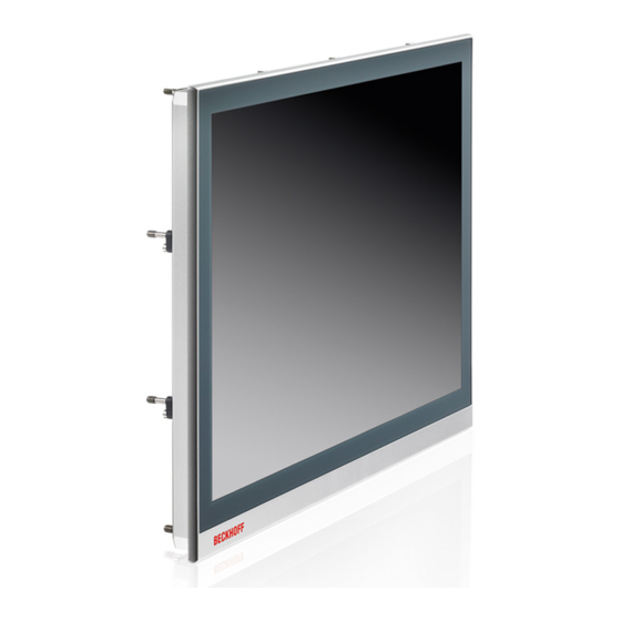
Product overview Structure Figure 2 shows the device configuration as an example of all CP29xx versions. Depending on the product version, the interfaces of the control panel on the connection block vary. Otherwise, there are no differences in the external design of the device. 10 9 Fig. 2: CP29xx_Structure Table 1: Legend CP29xx structure... -
Page 11: Fig. 3 Cp29Xx_Structure Stainless Steel Device
Product overview Fig. 3: CP29xx_structure stainless steel device Table 2: Legend structure CP29xx stainless steel device Component Description Clamping lever Mounting the control panel in the panel of the control cabinet Seal Protection of the connection section from moisture Name plate Information on the control panel equipment Display and touch screen glass Operating the control panel Access to interfaces... -
Page 12: Cp29Xx-0000 Interface Description
The plug is included in the delivery. You can obtain a replacement plug from your Beckhoff Sales using the following ordering option: • C9900-P927: power supply connector for CP29xx, 5-pin connector with strain relief for the external supply cable Version: 3.6... -
Page 13: Fig. 5 Cp29Xx_Usb Interface Pin Numbering
Product overview 3.2.2 USB output The CP29xx-0000 Control Panel has two USB outputs (X102, X103) with socket type A. The interfaces are used to connect peripheral devices with USB connection. USB specification 3.0 is supported for connection distances up to 3 m. USB specification 2.0 is supported for connection distances of more than 3 m or when USB-E is used. -
Page 14: Usb Input
Product overview 3.2.3 USB input The CP29xx-0000 Control Panel has a USB input (X104) with socket type B. The USB input is used to connect the control panel to the industrial PC. USB specification 3.0 is supported for connection distances up to 3 m. -
Page 15: Usb Extended Input
Product overview 3.2.4 USB Extended input The CP29xx-0000 Control Panel has a USB Extended input (X105) in the form of an RJ45 socket. The control panel is connected to the CU8801 USB-to-USB extended converter box via the interface. The connection is made via a standard RJ45 cable, not crossed. The interface transmits USB 2.0 at 480 Mbit/s. The socket does not represent an Ethernet port. -
Page 16: Dvi Extended Input
Product overview 3.2.5 DVI Extended input The CP29xx-0000 Control Panel has a DVI Extended input (X106). It is used to transmit the graphics signal from the industrial PC to the control panel. The graphics signal is transferred directly via a DVI cable over a distance of 50 m max. Such a cable length leads to strong distortion of the graphics signal on arrival at the control panel. -
Page 17: Cp29Xx-0010 Interface Description
The plug is included in the delivery. You can obtain a replacement plug from your Beckhoff Sales using the following ordering option: • C9900-P927: power supply connector for CP29xx, 5-pin connector with strain relief for the external... -
Page 18: Usb Output
Product overview 3.3.2 USB output The CP29xx-0010 Control Panel has two USB outputs (X102, X103) with socket type A. The interfaces are used to connect peripheral devices with USB connection. USB specification 2.0 is supported. X102 1 2 3 4 X10³ Fig. 10: CP29xx_USB interface pin numbering Table 9: USB interface pin assignment... -
Page 19: Cp-Link 4
Product overview 3.3.3 CP-Link 4 The CP29xx-0010 Control Panel has a CP-Link 4 input (X104) in the form of an RJ45 socket. This is not an Ethernet port. Via the interface, the control panel can be connected to an industrial PC at a distance of up to 100 m. -
Page 20: Fig. 13 Cp29Xx-0010_Cp-Link 4, Cu8802
Product overview CP-Link 4 (100 m) CU8802-0000 0000 CP-Link 4 (100 m) CP-Link 4 (100 m) Fig. 13: CP29xx-0010_CP-Link 4, CU8802 When installing the CP29xx-0010 with the CU8803 transmitter box, the industrial PC is likewise connected to the transmitter box via USB and DP/DVI. The transmitter box is then connected to the control panel via the CP-Link 4 connection of the transmitter box using a CP-Link 4 cable. - Page 21 Product overview • CU8802-0001: DisplayPort to DVI cable included with box • CU8803-0000: DVI-to-DVI cable included in the box • CU8803-0001: DisplayPort to DVI cable included with box CP29xx Version: 3.6...
-
Page 22: Optional Usb Interface
Product overview Optional USB interface You can expand the CP29xx beyond the basic configuration with an additional USB interface. The following ordering options are available: • USB (order identifier: C9900-E268) The ordering option is not available for the CP29xx in combination with a push button extension or a stainless steel front. -
Page 23: Name Plate
Product overview Name plate The name plate is shown as an example of all versions of the control panel. xxxxxxxx Fig. 17: CP29xx_name plate example Table 12: Legend for CP29xx name plate Description Model: the last four digits indicate the product variant. Serial number (BTN) Date of manufacture Display... -
Page 24: Connection Cables/Connection Kits
Product overview Connection cables/connection kits Different connection cables or connection kits are available, depending on the product version. 3.6.1 CP29xx-0000 connection kits The following connection kits are available for the CP29xx-0000: Table 13: CP29xx-0000 connection kits Connection kits Description C9900-K622 1 m connection kit for CP29xx-0000, consisting of: 1 m DVI cable, 1 m USB 3.0 cable C9900-K623 3 m connection kit for CP29xx-0000, consisting of:... -
Page 25: Cp29Xx-0010 Connection Cables
Product overview 3.6.2 CP29xx-0010 connection cables The following connection cables are available for the CP29xx-0010: Table 14: CP29xx-0010 connection cables Connection cable Description C9900-K671 RJ45 connection cable CAT.6 , 3 m C9900-K672 RJ45 connection cable CAT.6 , 5 m C9900-K673 RJ45 connection cable CAT.6 , 10 m C9900-K674 RJ45 connection cable CAT.6... -
Page 26: Commissioning
If you, as the user, require additional protection for the touch screen against dirt or scratching, for example due to dirty hands, this can be achieved with a Beckhoff protective film. The film provides short-term protection for a few days. -
Page 27: Transport And Unpacking
5. Check the contents for visible shipping damage. 6. In case of discrepancies between the package contents and the order, or in case of transport damage, please inform Beckhoff Service (see Chapter 9.1 Service and support [} 44]). CP29xx Version: 3.6... -
Page 28: Installation In The Control Cabinet
1 mm and 3 mm. After installation, be sure to check the tightness between the control panel and the installation wall. Take the dimensions from the current drawings on our homepage under the link: http://download.beckhoff.com/download/Technical_Drawings/Industrial_PC/Control_Panel/CP29xx Version: 3.6 CP29xx... -
Page 29: Fig. 18 Cp29Xx_Delivery State Clamping Lever
Commissioning 4.2.2 Installation in the control cabinet Preparation of the control cabinet The control cabinet must have the required installation cutout according to the device dimensions (see Chapter 4.2.1 Dimensions [} 28]) of the control panel. NOTE Extreme environmental conditions Extreme environmental conditions can cause damage to the device. •... -
Page 30: Fig. 19 Cp29Xx_Wall Positioning
Commissioning Fig. 19: CP29xx_wall positioning 2. Fold out the clamping levers 90° (section A and B). 3. Tighten the clamping levers with the Allen key 3.0 mm (section C). Fig. 20: CP29xx_control cabinet installation Version: 3.6 CP29xx... -
Page 31: Connecting The Control Panel
Commissioning Connecting the control panel CAUTION Risk of electric shock Dangerous touch voltages can lead to electric shock. To avoid electric shock, observe the following: • Never connect or disconnect the device cables during a thunderstorm. • Provide protective earthing for handling the device. To prepare the control panel for operation, you have to connect it. -
Page 32: Installing The Supply Cable
It consists of a 5-pin connection strip and a strain relief housing with cable tie. If you require a replacement for the voltage connector or the strain relief housing, you can order these from Beckhoff Sales using the following ordering option: • C9900-P927: power supply connector for CP29xx multi-touch built-in Control Panel, 5-pin connector... -
Page 33: Fig. 22 Cp29Xx_Disassembly Of Strain Relief Housing
Commissioning Fig. 22: CP29xx_Disassembly of strain relief housing CP29xx Version: 3.6... -
Page 34: Grounding The Control Panel
Commissioning 4.3.2 Grounding the control panel Potential differences are minimized and electrical currents are diverted to the ground through grounding or potential equalization of electronic devices. This is to prevent dangerous touch voltages and electromagnetic interference. Protective earth Establish low-resistance protective earth of the control panel via the voltage connection to avoid dangerous touch voltages. -
Page 35: Connecting Cables And Power Supply
Commissioning 4.3.3 Connecting cables and power supply NOTE Incorrect connection procedure Incorrect procedure when connecting the cables and the power supply can cause hardware damage. • Follow the documented procedure for connecting the cables and the power supply. • Always connect all cables first and only then switch on the power supply. •... -
Page 36: Shutting Down
Shutting down Shutting down NOTE Hardware damage due to power supply A connected power supply can cause damage to the control panel during disassembly. • Disconnect the power supply from the device before starting to disassemble it. When taking the control panel out of operation, you must first disconnect the power supply and cables. You can then remove the device from the control cabinet. -
Page 37: Disassembly And Disposal
Shutting down Disassembly and disposal Before you can remove the control panel from the control cabinet, you must first disconnect the power supply and the cables (see chapter 5.1 Disconnecting the power supply and cables [} 36]). To remove the control panel from the control cabinet, follow the steps shown in Fig. 23: 1. -
Page 38: Servicing And Maintenance
• cold water with a heated device • high water pressure, e.g. high-pressure cleaner Repair Only the vendor may repair the device. If a repair should be necessary, contact Beckhoff Service (see Chapter 9.1 Service and support [} 44]). Version: 3.6... -
Page 39: Cleaning The Front Screen
Cleaning the front screen You can clean the front screen of the control panel during operation. In order to avoid inadvertent touch entries when doing this, you must first set the device to "Cleaning Mode" with the help of the Beckhoff Control Tool. -
Page 40: Exchange Seal
The seal may become porous after a long period of operation. In that case, you should replace the seal to continue protecting the connection section. You can order the following replacement seals from your Beckhoff distributor. Table 15: Ordering options seal... -
Page 41: Fig. 27 Cp29Xx_Exchange Seal
Servicing and maintenance To replace the seal, follow the steps shown below in figure 27: 1. Loosen and remove the 16 M2.5x4 screws (section A). 2. Remove the seal (section B). 3. Place the new seal in the circumferential sealing groove on the back of the device (section C). 4. -
Page 42: Troubleshooting
Problem with the cable connections CP29xx-0000: check DVI cable connection CP29xx-0010: 1. Check the cable connec- tions 2. Check the CU880x diagnos- tic LEDs 3. Check the power supply Beckhoff recommends using Beckhoff connection cables and connection kits. Version: 3.6 CP29xx... -
Page 43: Technical Data
Technical Data Technical Data Table 17: Technical data Product designation CP29xx Weight aluminum front/stainless CP2907: 1.5 kg / 1.8 kg steel front CP2912: 3.0 kg CP2913: 2.8 kg / 3.1 CP2915: 3.7 kg CP2916: 4.2 kg / 4.5 kg CP2918: 5.1 kg / 5.4 kg CP2919: 5.4 kg CP2921: 5.9 kg / 6.2 kg CP2924: 7.2 kg Supply voltage... -
Page 44: Appendix
Phone: + 49 (0) 5246/963-0 Fax: + 49 (0) 5246/963-198 e-mail: info@beckhoff.de The addresses of the worldwide Beckhoff branch offices and agencies can be found on our website at http:// www.beckhoff.com/. You will also find further documentation for Beckhoff components there. -
Page 45: Table 18 Approvals Cp29Xx
Appendix Approvals The following table shows the approvals of the control panel according to the product version: Table 18: Approvals CP29xx Product version Approvals CP29xx-0000 CE, EAC, UKCA, FCC CP29xx-0010 CE, EAC, UKCA, FCC You will find all other applicable approvals on the name plate of your device. FCC approvals for the United States of America FCC: Federal Communications Commission Radio Frequency Interference Statement This device was tested and complies with the limits for a digital device of class A, according part 15 of the... - Page 46 List of figures List of figures Fig. 1 CP29xx_without and with push button extension................. Fig. 2 CP29xx_Structure ........................Fig. 3 CP29xx_structure stainless steel device..................Fig. 4 CP29xx_voltage socket pin numbering..................Fig. 5 CP29xx_USB interface pin numbering..................Fig. 6 CP29xx_USB input pin numbering....................Fig.
- Page 47 List of tables List of tables Table 1 Legend CP29xx structure......................Table 2 Legend structure CP29xx stainless steel device................Table 3 Voltage socket pin assignment ....................Table 4 USB interface pin assignment...................... Table 5 USB interface pin assignment...................... Table 6 USB E input pin assignment ......................Table 7 DVI Extended interface pin assignment ..................
- Page 49 More Information: www.beckhoff.com/cp29xx Beckhoff Automation GmbH & Co. KG Hülshorstweg 20 33415 Verl Germany Phone: +49 5246 9630 info@beckhoff.com www.beckhoff.com...
Need help?
Do you have a question about the CP29 Series and is the answer not in the manual?
Questions and answers