Table of Contents
Advertisement
Quick Links
Advertisement
Chapters
Table of Contents

Related Manuals for Beckhoff CP6906-0001-0010


Summary of Contents for Beckhoff CP6906-0001-0010
- Page 1 Manual | EN CP6906-0001-0010 Control Panel 2023-07-19 | Version: 2.0...
-
Page 3: Table Of Contents
5 Decommissioning ........................... 23 Disconnecting the power supply and cables ................... 23 Disassembly and disposal....................... 24 6 Maintenance ............................ 25 7 Troubleshooting ............................ 27 8 Technical data ............................ 28 9 Appendix .............................. 29 Service and support ........................ 29 Approvals ............................ 30 CP6906-0001-0010 Version: 2.0... - Page 4 Table of contents Version: 2.0 CP6906-0001-0010...
-
Page 5: Notes On The Documentation
Copyright © Beckhoff Automation GmbH & Co. KG. Publication of this document on websites other than ours is prohibited. Offenders will be held liable for the payment of damages. All rights reserved in the event of the grant of a patent, utility model or design. -
Page 6: For Your Safety
Exclusion of liability Beckhoff shall not be liable in the event of non-compliance with this documentation and thus the use of the devices outside the documented operating conditions. -
Page 7: Fundamental Safety Instructions
• the operating instructions are in good condition and complete, and always available for reference at the location where the products are used. CP6906-0001-0010 Version: 2.0... -
Page 8: Notes On Information Security
For your safety Notes on information security The products of Beckhoff Automation GmbH & Co. KG (Beckhoff), insofar as they can be accessed online, are equipped with security functions that support the secure operation of plants, systems, machines and networks. Despite the security functions, the creation, implementation and constant updating of a holistic security concept for the operation are necessary to protect the respective plant, system, machine and networks against cyber threats. -
Page 9: Product Overview
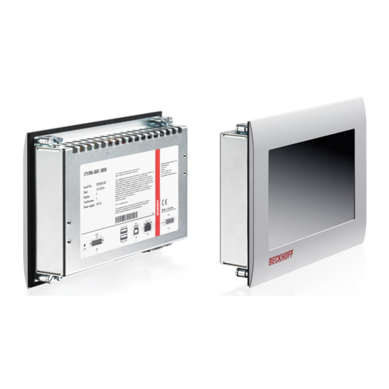
• C9900-G071: push button extension for CP6x06 with horizontal 7-inch display For explanations of the push button extensions and the functions, refer to the manual C9900-G070/G071. Figure 1 shows the control panel without (A) and with (B) push button extension. Fig. 1: Without and with push button extension CP6906-0001-0010 Version: 2.0... -
Page 10: Structure
Access to interfaces Interfaces on the underside Display and touch screen glass Operating the control panel Interface description The CP6906-0001-0010 has the following interfaces: • Power supply (X101) • USB output (X102, X103) • USB input (X104) • USB Extended input (X105) •... -
Page 11: Power Supply
The plug is included in the delivery. You can obtain a replacement plug from your Beckhoff Sales using the following ordering option: • C9900-P927: Power supply connector for CP690x Control Panel, 5-pin connector with strain relief for the external supply cable 3.2.2... -
Page 12: Usb Input
Fig. 7: USB-E input pin numbering Table 5: USB-E input pin assignment Signal Description T2 + Pair 2 T2 - T3 + Pair 3 T1 + Pair 1 T1 - T3 - Pair 3 T4 - Pair 4 T4 - Version: 2.0 CP6906-0001-0010... -
Page 13: Name Plate
The name plate provides information about the control panel equipment. The name plate shown here serves only as an example. xxxxxxxx Fig. 8: Name plate Table 6: Legend name plate CP6906-0001-0010 Description Model: The last four digits indicate the device generation. Serial number (BTN) -
Page 14: Connection Kits
Product overview Connection kits The following optional connection kits are available: Table 7: Connection kits CP6906-0001-0010 Connection kits Description C9900-K560 1 m connection kit for CP69xx, consisting of: DVI cable 1 m, USB cable 1 m C9900-K513 3 m connection kit for CP69xx, consisting of: DVI cable 3 m, USB cable 3 m... -
Page 15: Commissioning
If you, as the user, require additional protection for the touch screen against dirt and scratching, for example due to dirty hands, this can be achieved with a Beckhoff protective film. You can either order your device directly with the protective film applied or order a film individually and apply it yourself. -
Page 16: Transport And Unpacking
• Only install the control panel in the corresponding wall in the orientation shown. The CP6906-0001-0010 Control Panel is designed for installation in the front of a control cabinet in machine and system engineering. Please observe the environmental conditions prescribed for the operation (see Chapter 8 Technical data [} 28]). -
Page 17: Fig. 9 Delivery State Clamping Lever
To install and secure the control panel in the control cabinet, follow the steps shown in Fig. 10 and 11: 1. Insert the control panel at the intended position in the control cabinet wall. Make sure that the device is secured against falling out until it is fastened properly. CP6906-0001-0010 Version: 2.0... -
Page 18: Fig. 10 Wall Positioning
Commissioning Fig. 10: Wall positioning 2. Fold out the clamping levers 90° (section A and B). 3. Tighten the clamping levers with the Allen key 3.0 mm (section C). Fig. 11: Control cabinet installation Version: 2.0 CP6906-0001-0010... -
Page 19: Connecting The Control Panel
If you require a replacement for the voltage connector or the strain relief housing, you can order these from Beckhoff Sales using the following ordering option: • C9900-P927: power supply connector for CP69xx or CP66xx Control Panel, 5-pin connector with strain... -
Page 20: Grounding The Control Panel
12) and the central grounding point of the control cabinet in which the panel is installed. Use wires with a cross-section of at least 4 mm or a flat conductor for the ground connection, as the circumference of the conductor should be as large as possible. Fig. 12: Ground connection Functional earthing Version: 2.0 CP6906-0001-0010... -
Page 21: Connecting Cables And Power Supply
When connecting the control panel to an industrial PC with UPS output, Beckhoff recommends using this for the connection so that the display is also active in UPS mode. Only one control panel may be connected to the UPS output on the PC. -
Page 22: Fig. 13 Assembly Of The Strain Relief Housing
1. Use your fingers to bend the latching lugs on the lower part slightly outwards (see Fig. 14). 2. Lever the upper part off the lower part. 3. Cut the cable tie. ð You have removed the strain relief housing. Fig. 14: Disassembly of the strain relief housing Version: 2.0 CP6906-0001-0010... -
Page 23: Decommissioning
6. Make a note of the wiring of all data transmission cables if you want to restore the cabling with another device. 7. Disconnect all data transfer cables from the control panel. 8. Finally, disconnect the ground connection. ð You have disconnected the power supply and the cables. CP6906-0001-0010 Version: 2.0... -
Page 24: Disassembly And Disposal
ð You can now remove the control panel from the corresponding cutout in the control cabinet wall. Fig. 16: Wall positioning Disposal of the control panel When disposing of the control panel the national electronic waste regulations must be followed. For disposal, you must remove the device from the control cabinet. Version: 2.0 CP6906-0001-0010... -
Page 25: Maintenance
Cleaning the front screen You can clean the front screen of the control panel during operation. In order to avoid inadvertent touch entries when doing this, you must first set the device to "Cleaning Mode" with the help of the Beckhoff Control Tool. -
Page 26: Fig. 17 Select Cleaning Mode
5 and 120 seconds. Right-click the sun symbol again and click "Options". Now select the appropriate period (see Fig. 18). Fig. 18: Options Repair Only the vendor may repair the device. If a repair should be necessary, contact Beckhoff Service (see Chapter 9.1 Service and Support [} 29]). Version: 2.0 CP6906-0001-0010... -
Page 27: Troubleshooting
Cycle time in TwinCAT set to 10 ms Increase the cycle time to TwinCAT via USB (standard) between 50 ms and 80 ms No picture/backlight Problem with the cable connections Check DVI cable connection Beckhoff recommends using Beckhoff connection cables and connection kits. CP6906-0001-0010 Version: 2.0... -
Page 28: Technical Data
Technical data Technical data Table 9: Technical data Product designation CP6906-0001-0010 Supply voltage 22-30 V (24 V power supply unit, NEC class 2) Weight approx. 0.9 kg Maximum power consumption with approx. 12 W basic configuration Protection rating Front IP54, rear IP20 Vibration resistance (sinusoidal EN 60068-2-6: 10 ... -
Page 29: Appendix
33415 Verl Germany Phone: + 49 5246/963-0 email: info@beckhoff.de The addresses of the worldwide Beckhoff branches and agencies can be found on our website at http:// www.beckhoff.com/. You will also find further documentation for Beckhoff components there. CP6906-0001-0010 Version: 2.0... -
Page 30: Approvals
FCC approvals for Canada FCC: Canadian Notice This device does not exceed the class A limits for radiation, as specified by the Radio Interference Regulations of the Canadian Department of Communications. Version: 2.0 CP6906-0001-0010... - Page 31 Assembly of the strain relief housing ................... Fig. 14 Disassembly of the strain relief housing..................Fig. 15 Removal from the control cabinet ....................Fig. 16 Wall positioning ..........................Fig. 17 Select Cleaning Mode ........................Fig. 18 Options............................CP6906-0001-0010 Version: 2.0...
- Page 32 Table 3 USB interface pin assignment...................... Table 4 USB interface pin assignment...................... Table 5 USB-E input pin assignment ......................Table 6 Legend name plate CP6906-0001-0010 ..................Table 7 Connection kits CP6906-0001-0010 .................... Table 8 Troubleshooting ........................... Table 9 Technical data..........................
- Page 34 More Information: www.beckhoff.com/cp6906-0001-0010 Beckhoff Automation GmbH & Co. KG Hülshorstweg 20 33415 Verl Germany Phone: +49 5246 9630 info@beckhoff.com www.beckhoff.com...
Need help?
Do you have a question about the CP6906-0001-0010 and is the answer not in the manual?
Questions and answers