Vivax Metrotech vCam-6 User Manual
Inspection system
Hide thumbs
Also See for vCam-6:
- Training (97 pages) ,
- User handbook manual (89 pages) ,
- Manual (12 pages)

Related Manuals for Vivax Metrotech vCam-6


Summary of Contents for Vivax Metrotech vCam-6
- Page 1 Inspection System User Manual Vivax-Metrotech Corporation 4.04.000087 04/01/2024 V1.5...
- Page 3 General Safety & Care Information Health and Safety The heat from camera head LEDs ‹ ‹ This equipment is primarily used for inspecting sewer The camera head may pipes by professionals operating in the sewer and become hot when left on plumbing industry and maintained by professionals while not performing an Camera LEDs may...
- Page 4 Under Industry Canada regulations, this radio transmitter may only operate using an antenna of a type and maximum (or lesser) gain approved for the transmitter by Industry Canada. To reduce potential radio interference to other users, the antenna type and its gain should be so chosen that the equivalent isotropically radiated power (e.i.r.p.) is not more than that necessary for successful communication.
-
Page 5: Table Of Contents
1.3 Request for Service........................3 1.4 Worldwide Sales Offices and Service Centers................3 2. Introduction............................4 2.1 Icon Gallery..........................4 2.2 The vCam-6 Inspection Camera System..................6 2.3 Standard Equipment - Control Module..................6 2.4 vCam-6 Control Module Overview.....................7 2.5 vCam Series Cable Reels Overview..................9 2.5.1 Standard Equipment - Reels....................9 2.5.2 Type-CP Standard Reel....................10... - Page 6 Table of Content 4.4.2 Renaming a Video or JPEG Image File................32 4.4.3 Copy, Move or Delete Videos and Pictures..............33 4.5 File Format of SD Cards and USB Devices................34 4.6 Video Format...........................35 4.7 Troubleshooting Video Playback....................35 4.8 Corrupt Video Files........................35 5. Features Available During Recording....................37 5.1 Voice Over..........................37 5.2 Volume Control........................37 5.3 Display and Backlight Settings....................37...
- Page 7 Table of Content 9. Camera Skids..........................62 9.1 Camera Skids ..........................62 9.1.1 Camera and Spring Skids, Installing and Removing............62 9.1.2 Standard Skids, screw in setscrews, D18 series, D26-MX, D34 and D46 series....62 9.1.3 Standard Skids, Two-part clip together, D20-HD, D26-HD..........63 9.1.4 Spring Skids, Clamp around camera spring..............64 9.1.5 Guide Skids, Clamp around the camera head..............64 10.
-
Page 8: Service & Support
Always quote your camera system’s model, serial, and software revision numbers when requesting product support. 1.1.1 Control Module The vCam-6 Control Module model number and serial numbers are found on the back of the unit. Serial Number 1.1.2 Reels The serial numbers for the vCam series reels are on the label at the center of the frame opposite the locking and friction brakes. -
Page 9: Firmware Revision Location
Service & Support Remove the standard skid to view the serial number of the camera head. Serial Number D26-HD-07 The camera's serial number is etched across the length of the camera or in the recessed area of the camera housing. Firmware Revision Location The “About”... -
Page 10: Request For Service
Service & Support Request for Service If any system components need servicing, the more concise information provided will result in a quicker turnaround time. On our website, you can fill out a “Service Center Request” form, print it, and include it with the unit when shipping. Package the product well and ship it by a traceable method. -
Page 11: Introduction
Safety – Obey all safety messages that follow this symbol to avoid possible injury or death. Note – Important information that will affect the performance of the product. Tip – This tip may save you time or provide a better response. Icon Gallery This section lists the icons shown in the vCam-6. Icon Name Description Control Module Top Panel Press to Start and Stop a video recording. - Page 12 Introduction Sonde Sonde On/Off - and frequency selection control. Internal Internal Microphone - to record audio comments over the video Microphone recording. Microphone Microphone On/Off - glows red when the microphone is active. Charging Battery Charging Indicator will glow red while charging and turn Indicator green when fully charged.
-
Page 13: The Vcam-6 Inspection Camera System
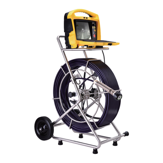
Introduction The vCam-6 Inspection Camera System The vCam-6 Inspection System comprises three major components: vCam-6 Control Module, vCam Series Reels, and Camera Heads. Standard Equipment - Control Module The below accessories will come with the vCam-6 Control Module. vCam-6 Control Module Interface... -
Page 14: Vcam-6 Control Module Overview
Introduction vCam-6 Control Module Overview The vCam-6 control module allows for the viewing, recording, and playback of Audio Video Interleave (AVI) format video and image capturing of Joint Photographic Experts Group (JPEG) pictures. Audio and text commentary can be added to the videos, and text commentary can be added to the captured pictures. - Page 15 Introduction Camera LED Dimmer - to raise, lower, or turn off the camera’s LED lighting. Distance Counter Reset - to reset the pushrod deployed distance to 0 Internal Microphone - to record audio comments over the video recording Battery Charging Indicator will glow red while charging and turn green when fully charged.
-
Page 16: Vcam Series Cable Reels Overview
Standard Equipment - Reels The Type-CP and MX reels include a pushrod with an installed termination spring assembly. The vCam-6 control module can be mounted and locked on top of the larger Type-CP reel, allowing viewing at a comfortable height. -
Page 17: Type-Cp Standard Reel
Type-CP Standard Reel Mounting Blocks For mounting and locking the vCam-6 control module in place. Cable Guide Assembly It helps control the deployment and retrieval of the pushrod cable by keeping it in a localized area. -
Page 18: Type-Mx Mini Reel
Introduction Sonde The sonde locate signal emits from this cup. A utility or sonde locator with a matching frequency can pick up this locate signal on the surface. Spring Termination It attaches to the pushrod and gives the flexibility to lead it through Assembly bends in the pipe. -
Page 19: Initial Control Module Setup
Initial Control Module Setup 3. Initial Control Module Setup Initial Control Module Setup 3.1.1 Installing the Fuse Install the 10 Amp - 250 Volt fuse in the fuse compartment on the back of the control module. The control module will operate without a fuse when using AC power, but the battery will not charge, and the unit will turn off when the AC power is removed. -
Page 20: About Control Module Settings
3.1.4 About Control Module Settings The initial setup of the vCam-6 control module is done with the keyboard. A USB or wireless mouse can also be used. All the settings selected are saved into the control module’s memory and will remain until changed. -
Page 21: Setting The Control Module Language
Initial Control Module Setup Default Storage Format This user handbook will cover each item in the Setup menu, Distance Counter Date/Time starting with the Language sub-menu. Afterward, the user Sonde handbook will cover each item in the Setup menu order from Wi-Fi top to bottom. -
Page 22: Setting The Distance Counter
Initial Control Module Setup 2. Select the Default Storage option at the top of the selection list. 3. Press Enter or use the right arrow key to move to the sub-menu with the list of options. Default Storage Record to HDD Format Record to SD Distance Counter... -
Page 23: Setting The Date, Time And Format
Initial Control Module Setup 4. Use the up / down arrow keys to highlight the choice. 5. Press the Enter key when the choice is highlighted, and the white box will be filled with a green check confirming the selection. Default Storage Format Distance Counter... -
Page 24: Setting The Sonde Frequency
Initial Control Module Setup Pressing the Enter key at any time will save the changes made. This allows separate changes to be made at any time to the time, time format, or date without moving through all available selections. 3.2.6 Setting the Sonde Frequency Setting the Sonde frequency allows the selection of either 33kHz, 512Hz, or 640Hz frequencies when the Sonde On/Off button is pressed. -
Page 25: Setting The Reel Type
Initial Control Module Setup Default Storage Format WiFi : Setup IP Address: 192.168.1.108 Distance Counter Date/Time WiFi: Setup WiFi: Sonde Router SSID: IP Address: 192.168.1.108 Wi-Fi Router SSID: vCam6106002 Change Video Out Language Router SSID Restore Cancel Factory Setup Only Reel Settings Password: Update... -
Page 26: Restore The Factory Default Settings
Initial Control Module Setup 5. Highlight the reel choice and sub-menu length choice if applicable. 6. Press the Enter key to save the changes. 7. Press the ESC key to return to the main Setup menu, and press ESC twice to return to the main screen. -
Page 27: Over-The-Air Updates
Initial Control Module Setup 3.2.10.1 Over-the-Air Updates All vCam-6 control modules running firmware version DVR_033 or later can use the vCam Mobile Controller app to update the control modules firmware. 1. Launch the vCam Mobile Controller app and connect to the vCam-6. - Page 28 Initial Control Module Setup 1. Extract the firmware update files and copy the .bin or .soc files to an SD or USB device. The files must be on the drive's root drive or card, i.e., the files must not be compressed or in a folder on the device.
- Page 29 Initial Control Module Setup 6. Use the up and down arrow keys to select the SD or USB device with the firmware loaded onto it. Press the Enter key. Default Storage Format Distance Counter Date/Time Sonde Wi-Fi Video Out Language Restore Update Firmware Reel Settings...
- Page 30 Initial Control Module Setup 8. Use the up and down arrow keys to highlight and select the .bin or .soc file and press Enter key. Default Storage Format Distance Counter Date/Time Sonde Wi-Fi Video Out Language Restore Update Firmware Reel Settings Startup Screen Update *.bin file...
-
Page 31: Update The Control Module Start Screen
Initial Control Module Setup 10. The control module will reboot. The firmware update is now complete. Verify that the firmware update was successful by checking the firmware version in the About section of the setup menu. UPDATE FINISHED Update success, system will restart, click “OK” to continue. File File setup... -
Page 32: Video Out
Initial Control Module Setup Default Storage Default Storage Format Format Distance Counter Distance Counter Date/Time Date/Time Message Sonde 33k/512/640 Sonde Version:vCam6_DVR_032 Wi-Fi Wi-Fi vCam6_MCU_6.04 Video Out Video Out Release date:2023.11.29 13:39:25 Language Language Video format:1080P NTSC Restore Restore Reel Settings Reel Settings Update Update... -
Page 33: Video Recording And Picture Image Capture
To accomplish these items, we must understand the menu system, file system, and navigation in them. Main File Menu The vCam-6 control module uses a cascading menu system that primarily uses the left , right , up , down arrow keys, Enter, and ESC keys to move through the menus and sub-menus. -
Page 34: File List Sub-Menu
Video Recording and Picture Image Capture 4.2.1 File List Sub-Menu The file list sub-menu shows the hard drive's files, videos, or pictures. Contents of an SD or USB device can also be viewed if they are currently plugged into the control module. In the video file list sub-menu, pausing on a video file will start a preview window. -
Page 35: File Option Sub-Menu
Video Recording and Picture Image Capture The video preview should take four to five seconds to appear and start playing. The fewer videos you have on the hard drive, the faster the preview will begin. The preview will take longer to pop up and play when the hard drive fills with videos and pictures. 4.2.2 File Option Sub-Menu The File Option sub-menu shows the options available for files selected in the previous file list sub- menu. -
Page 36: Video Recording And Playback Controls
Video Recording and Picture Image Capture Enter Pressing the Enter while in the: File List sub- Select the file by adding the green checkbox to the far right. menu File Option Will start the action of playing, copying, moving, or deleting. sub-menu Media Select The file will be moved to the SD or USB drive. -
Page 37: Making A Video Recording
Video Recording and Picture Image Capture Pause Recording Press the Pause key to pause the recording video. While the video is paused, the pause icon will appear on the bottom-left section of the status bar on the screen, and the elapsed recording time will pause. To resume recording, press the Pause key again, and the recording icon will replace the pause icon. -
Page 38: Jpeg Image Picture Capture
Video Recording and Picture Image Capture 4.3.2 JPEG Image Picture Capture Pictures will be saved to the default drive you selected in the initial control module setup screen. The pictures will be saved on the internal hard drive if no other drive is selected. 1. -
Page 39: View Picture Image Files
Video Recording and Picture Image Capture 4.4.1 View Picture Image Files: 1. Use the steps in section 4.4 to play videos and view pictures in the control module. 2. Only this time are you using picture images rather than video files. 4.4.2 Renaming a Video or JPEG Image File Video and picture files on the control module can be re-named from the default date format. -
Page 40: Copy, Move Or Delete Videos And Pictures
Video Recording and Picture Image Capture Message File rename complete Previous 6/45 Hard Drive (Default) Free:746.105GB 2310160953a 908Oct202..avi Total:971.525GB 2310160952b 908aOct20...jpg All Files 2310160952a Play 1430Oct20...avi play Video 2310160952a Copy 1430Oct20...avi backup Picture 2310160951b Move other..Other Storage 2310160951a Delete delete Rename Next... -
Page 41: File Format Of Sd Cards And Usb Devices
File Format of SD Cards and USB Devices The vCam-5 and vCam-6 control modules will recognize USB thumb drives and SD cards formatted in the FAT32 or NTFS file system and a maximum size of 64GB for SD cards and 128GB for USB thumb drives. -
Page 42: Video Format
Video Recording and Picture Image Capture Video Format The vCam-6 control modules use the MP4 video format. MP4 files were created under the ISO/IEC 14496-12:2001 standard by the ISO/IEC and Motion Picture Experts Group (MPEG). Because of this, MP4 is an international standard for audio-visual coding. - Page 43 Video Recording and Picture Image Capture If a file is copied or moved from the control module and will not play on a PC: • Check to see if the file will play in the control module. The file may have been corrupted during the move or copy if it does not play. Try to recopy the file again, ensuring it does not interrupt the process until it is finished.
-
Page 44: Features Available During Recording
Features Available During Recording 5. Features Available During Recording During a video recording, the following options are operational and usable: • Wi-Fi (see section 6, Wi-Fi) • Sonde (see section 10, Locating Sondes and Pushrod) • Audio Commenting (see section 5.1, Voice Over) •... -
Page 45: On-Screen Status Bar
Features Available During Recording 1. Use the up and down arrow keys to move between the color settings selections. 2. Use the left and right arrow keys to lower or raise the display settings. 3. Use the left and right arrow keys to turn the backlight on or off. -
Page 46: Text Writer
Features Available During Recording Text Writer 5.7.1 Introduction to the Text Writer The Text Writer function allows users to add descriptive text and comments to recorded videos and pictures. The user can customize the text description on the videos and pictures. The Text Writer has 20 pages with 14 lines and 30 characters per line per page to be saved and later recalled for use. - Page 47 Features Available During Recording F6 – Save Page – Use this key to save the Text Writer’s text into Saves the memory. When text is placed on the screen via the Text Writer, current page the page that contains the text can be saved into memory and of text recalled for future use.
-
Page 48: Text Writer Components
Features Available During Recording 5.7.3 Text Writer Components VCAM-6 “LIVE VIEW” INTERFACE STREAM LIVE VIDEO TO PC RECORD DIRECT TO PC HDD VIEW & DOWNLOAD PIC & VIDEO 03: 37: 07 8. 0FT 2023/ 12/ 10 Page1 Main viewing area... -
Page 49: Digital Zoom
Features Available During Recording Digital Zoom Use the zoom feature while viewing live, recorded, or jpeg captures. 1. Press the Zoom button on the top panel keypad to activate the zoom feature and bring up the red zoom control box on the screen. with the arrow keys to the area to be magnified and press the Enter key. -
Page 50: Wi-Fi
6. Wi-Fi Wi-Fi Connection for App The vCam-6 control module has built-in Wi-Fi that broadcasts an SSID (secure network name) and uses DHCP (the protocol that assigns an IP address needed to connect to the control module) to assign IP addresses to a tablet or smartphone running the VMC app. -
Page 51: Using The Cable Reels
Using the Cable Reels 7. Using the Cable Reels Do not use the control module as a handle to move the reel. Remove the control module or use the handle of the reel to move the reel. Cable Reel Overview 7.1.1 Mounting the Control Module 1. -
Page 52: Remove The Control Module
Using the Cable Reels 5. Plug the interconnect cable into the control module's bottom socket. This is a key plug and socket, so line up the red dot on the interconnect cable plug to the same red dot on the interconnect socket on the control module. a. -
Page 53: Pushrod Overview
Using the Cable Reels 7.1.3 Pushrod Overview The Pushrod Cable comprises a fiberglass rod surrounded by wire conductors and a Kevlar braid coated with a thick polypropylene jacket. Because of the harsh environment in which the pushrod is used, care should be taken to keep it in good operating condition. Check Pushrod for Wear –... -
Page 54: Deployment Of The Pushrod Cable
Using the Cable Reels 3. Position the base of the sonde cup into the cable guide and lock the cage, as shown below. The sonde cup (a) is now in the cable guide at a 12 O’clock, and the pushrod section from the cage to the sonde cup (b) is bent from the cage to the cable guide. - Page 55 Using the Cable Reels Cable Guide Locking Brake Friction Brake Type-CP Standard Reel Cable Guide Locking Brake and Friction Brake Type-MX Mini Reel 3. Turn the cable cage forward (clockwise) until the camera head is approximately at 9 o’clock position. 4.
- Page 56 Using the Cable Reels Tiger tail used on a Insert Sleeve Insert Sleeve in the cleanout maintenance hole Use “grip” type rubber gloves to better grip and protect your hands from sludge during retrieval. The gripping action of the gloves will help keep a good hold on the pushrod while deploying. Apply the push force to the pushrod as close to the entry point.
-
Page 57: Camera Heads And Terminations
Camera Heads and Terminations 8. Camera Heads and Terminations Parts of the Camera Heads D34 and D46 Series Cameras for Type-CP Standard Reel Polycarbonate LED cover Sapphire glass lens Camera Head Face Camera Base Threads Skid Screw Groves Main Housing Camera Head Body Alignment Key Connector Contact Pins... -
Page 58: Camera Head Options
(PAL or NTSC) and automatically reset itself to work in that format. The vCam-6 is an HD format control module and will record in full 1080p high definition when used with the HD version D34-HD and D46-HD camera heads. The vCam-6 will also work with older analog D34-M, D34-C, or D46-CP camera heads. -
Page 59: Spring Assembly Parts
Camera Heads and Terminations Spring Assembly Parts The Spring Assembly is comprised of the parts that connect the camera head on one end and are connected to the pushrod on the other. The spring assembly for the Type-CP Reel will consist of a spring, coiled cable assembly, and a pair of lanyards as separate parts. -
Page 60: Lanyard Set
Camera Heads and Terminations Connector Base Floating Camera Nut Main Cable Floating Camera Nut Connector Base Rear (short pushrod end) Termination Coiled Cable Assembly for Type-CP Reel Front (long camera end) Lanyard Slots O-Rings Keyed 4-Pin Camera Socket Connector Base Detail 8.2.4 8.2.4 Lanyard Set Lanyard Set... -
Page 61: Removing The Camera Head - D34 And D46 Series Cameras
Camera Heads and Terminations Coiled cable assembly, 12mm Fits D34 and D46 series Short cameras Spring Kit, 12mm Standard Kit includes a Spring, Coiled (33mm dia. x 11-3/4” / 30cm Cord Assembly and a pair of long spring) Steel Lanyards Kit includes a Spring, Coiled Spring Kit, 12mm Short (33mm Cord Assembly and a pair of... -
Page 62: Removing The Standard Reel's Termination Spring And Coiled Cable
Camera Heads and Terminations 6. Clean off grease and debris from the–ring at the camera's base and connection plug if needed. Store the camera head in a clean, dry place to prevent corrosion to any camera parts and prevent the pins from being damaged. If storing for long periods, remove the skid from the camera head. -
Page 63: Pre-Checking The Spring
Camera Heads and Terminations Check the Coiled Cable for: • Jacketing – Check that the jacket of the cable does not have any cuts or abrasions. When connected to a control module, wiggle the cable at the base of the connections to check for hidden breaks in the cable. -
Page 64: Pre-Checking The Camera Head Before Installing
Camera Heads and Terminations 3. Feed the two lanyards through the floating camera nut and insert it into the lanyard slots. Ensure the lanyards are straight and not tangled in the coiled cable. 4. Pull the floating camera nut up and over the lanyards. The 4-pin male plug and female socket used to mount the camera head are “keyed”... -
Page 65: Pre-Checking For Picture And Led Control
Camera Heads and Terminations 8.6.3 8.6.3 Pre-checking for Picture and LED Control Pre-checking for Picture and LED Control Visually check the 4-pin female connector on the camera and the 4-pin male connector on the coiled cable. Line up the keyed connector on the coiled cable to the camera head and attach them. Attach a reel to a control module and power it on. -
Page 66: Removing And Installing The Type-Mx Reels D18-Hd And D26-Hd Camera Heads
Camera Heads and Terminations 1. Use a swab applicator to apply a silicone grease bead onto the camera base's female threads. Use a fingertip and apply a bead of silicone grease on top of the 2 O-rings on the coiled cable connector. - Page 67 Camera Heads and Terminations The Type-MX reel is supplied with tools for camera and spring removal and installation. Wrench flats for camera and spring removal/installation Camera head removal 1. Use the section of the tool labelled TERM KIT to hold the flats on the spring.
-
Page 68: Removing And Installing The Spring Assembly
Camera Heads and Terminations Removing and Installing the Spring Assembly Don’t touch the green circuit board, gold pins on the spring sonde assembly, or camera head with bare hands. Touching these will transfer oils from the fingers to these components, leading to premature corrosion. -
Page 69: Camera Skids
Camera Skids 9. Camera Skids Camera Skids Camera skids are devices that attach to the camera head to 1) keep the camera head off the floor of the pipe to help avoid pushing up debris and dirt, which will end up on the camera lens, blocking your view, 2) allow the camera LED lighting to function better by keeping the lights more centered in the pipe allowing a more even spread of light on the pipe walls and ahead and 3) provide protection to the camera head by giving a shoveling effect which allows the camera head to be lifted over offsets... -
Page 70: Standard Skids, Two-Part Clip Together, D20-Hd, D26-Hd
Camera Skids Apply a layer of electrical tape over the screw holes on the installed skid. This will help keep debris from filling the screw slot, making removing them easier. 9.1.3 Standard Skids, Two-part clip together, D26-HD Tools Needed: No tools are needed. 1. Press in on the locking tabs while pulling the two parts apart. 2. -
Page 71: Spring Skids, Clamp Around Camera Spring
Camera Skids 9.1.4 Spring Skids, Clamp around camera spring D18-HD on the vCamDrain Spring Tools Needed: No tools are needed. 1. Press the locking tab to open the spring skid. 2. Present the open skid to the spring. 3. Close the skid and press until the locking tab clicks and locks into the mating part. - Page 72 Camera Skids 4. Check that the skid is secure by turning and pulling it simultaneously. Refrain from attempting to close the guide skid fins together completely. Doing so can result in damage to the camera head or the skid.
-
Page 73: Locating Sondes And Pushrod
Locating Sondes and Pushrod 10. Locating Sondes and Pushrod 10.1 Introduction The Type-CP and Type-MX reels include a locatable sonde at the base of the spring termination assembly. The controls for the sonde are located on the front panel of the control module. The newer version of the Type-CP reel (purchased after April 2014) and all MX reels can trace the entire pushrod length. -
Page 74: Sonde And Camera Locating
Locating Sondes and Pushrod 5. Turn on the utility locator transmitter and select a frequency. We recommend using a higher frequency, such as 33 kHz, 65 kHz, or 83 kHz. Ensure that the transmitter has good ground. The better the ground, the better the locator will perform. 6. -
Page 75: Troubleshooting
Troubleshooting 11. Troubleshooting Please check the Knowledge Center on the Vivax-Metrotech website for the latest support information. Go to www.vivax-metrotech.com and then click Support, Knowledge Center. PROBLEM: No power. The unit will not turn on: Check: 1. Check to see if the fuse is installed, blown, or damaged in any way. The unit will not charge your battery if the fuse is not installed. - Page 76 Troubleshooting PROBLEM: Not recording: Check: 1. Check the battery level. The unit may not have enough power to record when the battery is low. 2. Check available disk space on the HDD, USB, or SD card. 3. Check your default storage setting. PROBLEM: Sonde is not working: Check: 1.
- Page 77 Troubleshooting PROBLEM: No audio being heard on recorded video: Check: 1. Check that the volume is turned up during playback. Use the key function Ctrl – to lower the volume and Ctrl + to raise the volume. 2. Ensure that the red microphone icon is on the status bar and that the microphone button is illuminated during the audio recording.
- Page 78 Illustrations used in this manual's preparation will inevitably show some resemblance to similar images from other manufacturers. These manufacturers have permitted the use of their graphics, and this statement is intended to attribute such credit. iOS is a Cisco Systems, Inc. trademark registered in the U.S. Android, Google and Google Maps are registered trademarks of Google LLC.
- Page 80 Vivax-Metrotech Corporation 3251 Olcott Street, Santa Clara, CA 95054, USA Toll-Free: 1-800-446-3392 Phone: +1 (408) 734-3880 Website: www.vivax-metrotech.com Online Manual © 2024 Vivax-Metrotech Corporation...
Need help?
Do you have a question about the vCam-6 and is the answer not in the manual?
Questions and answers