Vivax Metrotech vCam-6 Training
Hide thumbs
Also See for vCam-6:
- User handbook manual (89 pages) ,
- User manual (80 pages) ,
- Manual (12 pages)

Related Manuals for Vivax Metrotech vCam-6


Summary of Contents for Vivax Metrotech vCam-6
- Page 1 Training vCam-6 Control Module with Standard Type-CP Reel and Type-MX Mini Reel...
-
Page 2: Table Of Contents
Table of Content • Introduction Changing the Camera Heads and • Spring Assemblies vCam-6 Control Module • Software Updates • • Type-CP Standard Reel • Type-MX Mini Reel Add a Start Screen • vCam-6 Menu Structure • Compatibility, Camera Specifications •... -
Page 3: Introduction
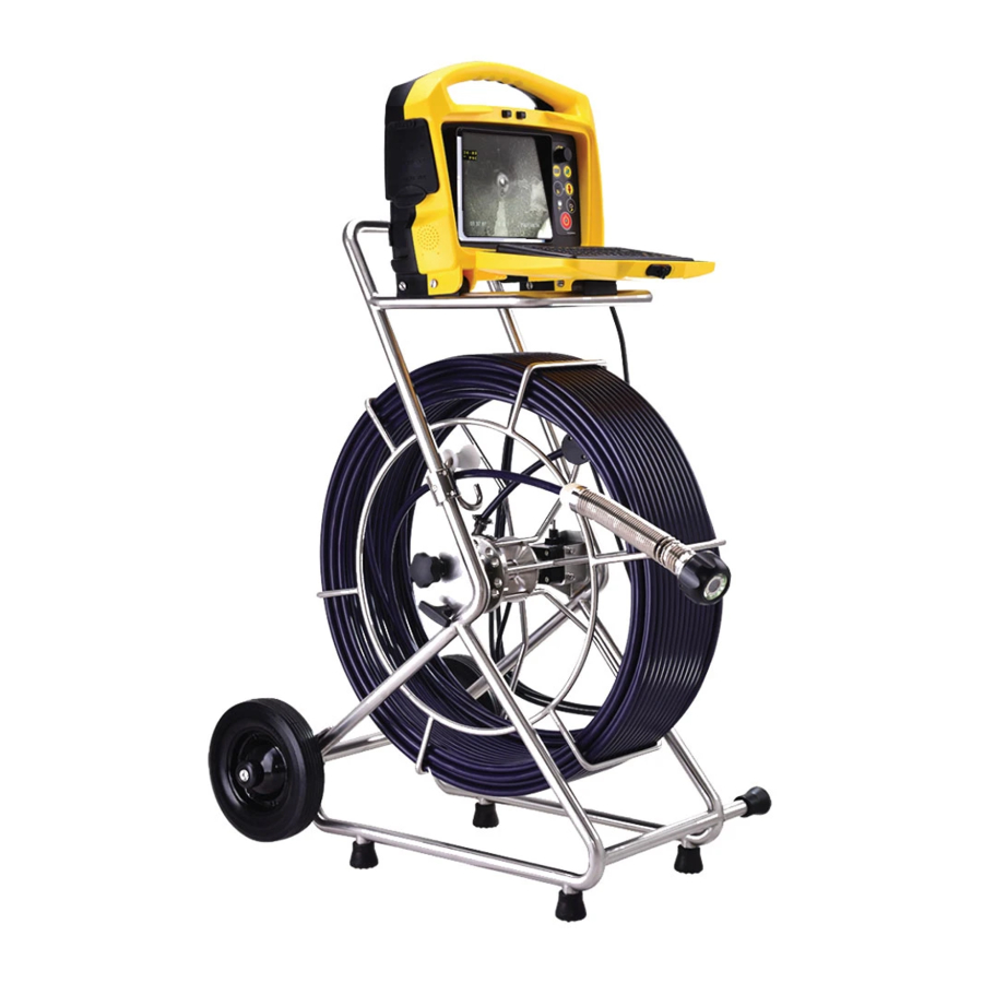
Introduction... - Page 4 Introduction This training presentation covers the vCam-6 Control Module, Type-CP Standard Reel, and optional Type-MX Mini-Reel. vCam-6 control module mounted MX Mini reel with the on the Type-CP reel vCam-6 control module...
- Page 5 Introduction At any time press the F1 Help key to access screens explaining the features of the vCam-6 control module. The heart of the vCam Inspection System is the control module. The vCam-6 control module has lots of advanced features but is still easy...
-
Page 6: Vcam-6 Control Module
Control Module... - Page 7 Fuse Installation Install the 10-amp fuse that was provided with the control module. This fuse is necessary for the internal Li-ion battery to charge. The fuse compartment is located on the back of the unit in the bottom 1. Remove fuse cap left corner.
- Page 8 Latch Assembly Slide the latch to the right to release the keyboard.
- Page 9 Power – On/off Press the Power button and the control module will begin its startup. The on/off button will glow green while the control module is turned on. The battery status icon will appear on the screen in the bottom right corner. Press and hold the power button for five seconds to turn off.
- Page 10 Power and Charging The control module can be used while charging via AC or DC current. DC Power AC Power A six-hour charge will supply approximately six hours of battery life. Only activate the sonde and wi-fi features when needed as they will affect the battery life.
- Page 11 Status Bar Text from text writer The status bar (grey bar at the bottom of the screen) shows any activated options such as the sonde or microphone and other information such as recording status and video length. Status Bar showing: Recording in progress Elapsed recording time Active Microphone...
- Page 12 Status Bar – Show and Hide The status bar can be hidden providing a larger viewing area. The status icons Show will still appear with the bar hidden. Press and hold the Ctrl key and tap the F10 Menu key to hide or show the status bar.
- Page 13 – Other Features - Front Panel The vCam-6 Control Module has other features available. The features located on the front panel are: Camera LED Dimmer Turn the knob to turn on the camera LEDs and to control their brightness.
-
Page 14: Type-Cp Standard Reel
Type-CP Standard Reel... - Page 15 The Type-CP Standard Reel Control module mounting blocks Interconnect Cable Horizontal position feet Rubber feet Pushrod Cage Cable guide Camera Heads Locking and friction brakes D34-HD D46-HD Pipe Insert Pushrod Tracing post Sleeve...
-
Page 16: The Type-Cp Standard Reel
The Type-CP Standard Reel – Mount the Control Module Line up the mounting pins to the bracket slots. Place into the bracket slots and push backward until the locking tab locks into place. Remove by pressing down on the locking tab while pulling the control module forward and up. - Page 17 Using the Type-CP Reel For best results from the distance counter, follow these instructions starting with the control module turned off. 1. Turn the cage to approximately the 9- 2. Hold the cage at the 9 O’clock position, 4. Attach the interconnect cable to the O’clock position using the sonde cup as grab the spring assembly, and thread the control module.
-
Page 18: Type-Mx Mini Reel
Type-MX Mini Reel... -
Page 19: Cable Guide
The Type-MX Mini Reel Horizontal position feet Stainless-steel frame Name plate Cable guide Locking and friction brake Pushrod tracing post Rubber feet Carbon fiber pushrod drum Camera Heads Reel to control module Pipe Insert Sleeve Interconnect Cable is included with the is included with the Type-MX reel D26-MX D18-MX... - Page 20 Using the Type-MX Reel For best results from the distance counter, follow these instructions starting with the control module turned off. 1. Turn the cage to approximately the 2. Reach into the cage and grab the 4. Power on the control module. 9-o’clock position using the sonde cup as spring assembly and thread the pushrod When the control module starts it will...
- Page 21 Using the Reel – Connect the Reel An Interconnect Cable is supplied with both Type-MX and Type-CP reels. Note: The plug and socket are keyed connectors identified on both the plug and socket by a red dot. On the control module the red dot is located at the 12 o’clock position. (Interconnect cable socket) Push the plug into the socket and release...
- Page 22 Using the Reel – Connect the Reel An Interconnect Cable is supplied with both Type-MX and Type-CP reels. NOTE When securing the interconnect cable slack, do Use the Velcro strap attached to not leave the angle of the cable from the socket the interconnect cable to secure at a sharp bend.
- Page 23 Using the Reel – Protecting the Pushrod Use a Pipe Insert Sleeve or Tiger Tail to keep the pushrod from scraping against sharp edges at the pipe. entrance.
-
Page 24: Vcam-6 Menu Structure
Menu Structure... - Page 25 Menu Structure – Main Menu Press the F10 Menu key to bring up the main menu. Use the Up/Down arrow keys to select Video, Pictures, All Files or Other Storage. Use the Right Arrow key or press the Enter key to move to the next menu.
- Page 26 Menu Structure Main Menu File List Menu Copy or Actions move to location Press F10 to bring Use the Right Use the Right Use the Right up the main menu Arrow to move Arrow key to Arrow key to...
- Page 27 Menu Structure – File List Sub-menu Use the Up/Down arrow keys to select video(s) or picture(s) files to play, copy, move, delete or rename. Press the Enter key to confirm the selection of the file and a green check...
- Page 28 Menu Structure – Selecting multiple files Multiple files can be selected for copying, moving or deleting within one page or across several pages. Use the Up/Down Arrow keys to highlight files. Press the Enter key to confirm the selection of each file and a green check mark will appear to the right of the file name.
- Page 29 Menu Structure – Menu Actions Sub-menu Use the Up/Down arrow keys to select the desired action. Press the Enter key or Right Arrow key to execute the desired action. Play - Press Enter or use the Right Arrow key to begin playing a video file.
-
Page 30: Video Recording
Video Recording... - Page 31 Video Recording – Create a new video Press the Record button on the top keypad. The flashing recording icon will appear in the status bar with elapsed recording time. Press Pause to pause the video. Press Pause again to resume the recording. Press Record or Stop to end the recording.
- Page 32 Video Recording – About Recordings Recording videos can pause for one hour. • The maximum length for a video is one hour. • After one hour the recording will automatically • stop, be saved, and another recording will start. Pressing the record key while the video is •...
- Page 33 Options Available while Recording While recording a video the following features are available: Text overlay Distance counter reset Voice-over audio JPEG Image capture commenting Pause and resume Sonde location and Save and recall pages LACP features via mini the recording pushrod tracing of saved text USB and Video out ports...
- Page 34 JPEG Image Capture - Take a Picture Press the Camera button on the top keypad. A Camera icon will flash in the status bar giving confirmation.
- Page 35 Playing Videos and Viewing Pictures Use the text writer to add text to the first 10 seconds of the video. When looking at the preview window this may make it easier to identify your targeted video. Highlight the video or When finished press the Highlight Play Press F10, Highlight All...
- Page 36 Options While Playing While playing a video Use the controls on the top media keypad while the video is playing to: Play video or view Take pictures from the Pause the playing of the Rewind Fast forward picture playing video...
- Page 37 – Rename Files A confirmation box Select the file, use the Right Highlight Rename, use Enter the new file Arrow key. the Right Arrow key. name in the dialog will appear showing box and press Enter. that the File rename...
-
Page 38: Text Overlay
Text Overlay... - Page 39 – Keyboard The vCam-6 control module comes with a full QWERTY keyboard customized for text overlaying and adjusting the settings in the control module. Press the F1 Help key to view the help screen describing all of the control module’s...
- Page 40 Text Overlay – OSD (on-screen display) Any text shown on the screen will appear in videos and pictures. (with the exception of the word “Page”) The OSD (on-screen display) consist of the control modules set time, date and distance counter. Press the “F2 Info”...
- Page 41 – Other Features - Keyboard The ESC key clears text from the screen and will “step back” to the previous step. The F1 Help key are pages which describe the icons and their meanings. The F2 Info key controls the position and color (Ctrl+F2) of the OSD shown on the LCD.
- Page 42 Text Overlay – Colors and Background Settings Any text shown on the screen will appear in videos and pictures. F3 – Text – Use the F3 Text key to change the text color from the default color of white to black, yellow or green. F4 –...
- Page 43 – Text Overlay The Text Writer has 20 pages with 14 lines and 30 characters per line per page to be saved and later recalled for use. The current page number is always shown on the same line as the on-screen display.
- Page 44 Text Overlay – Saving and Recalling Pages Use the F5 Recall key to show text from a saved page of text. Press the F5 Recall key and the recall icon and page number box will appear in the status bar. Use the Up/Down Arrow keys to go to the page number (on manually enter the page number using the keyboard) to be recalled and then press the Enter key.
- Page 45 Text Overlay – Deleting Pages of Saved Text Press the F5 Recall key and use the Up/Down Arrow keys to recall the page of text to be deleted. Press F7 Del Page to delete the page from memory. Note that you can also use the F8 Del All key to delete all of the pages from memory.
-
Page 46: Sonde Locating And Pushrod Tracing
Sonde Locating Pushrod Tracing... - Page 47 – Sonde Locating All vCam series reels come with built-in locatable sondes. Use the distance counter* as a reference to how far down the line the sonde is, and a locator to pinpoint the location and depth to the sonde.
- Page 48 Pushrod Tracing The entire length of deployed pushrod can be traced with the use of a utility locator’s transmitter. Attach the red “hot” lead to the Attach the black trace post on the “ground” lead to earth. reel. The length of pushrod will now carry Power on the transmitter and use a the locate signal and can be traced frequency of 33kHz or higher.
- Page 49 – Pushrod Tracing Transmitter Connection for MX Reel Black lead to ground Red lead to post Power on the transmitter and use a frequency of 33kHz or higher. The length of pushrod will now carry the locate signal and can be traced like a...
- Page 50 – Pushrod Tracing Transmitter Connection for Type-CP Reel Red lead to post Black lead to ground Power on the transmitter and use a frequency of 33kHz or higher. The length of pushrod will now carry the locate signal and can be traced like a...
-
Page 51: Changing The Camera Heads And Spring Assemblies
Changing Camera Heads and Spring Assemblies... - Page 52 The Type-MX Spring Assembly The spring assembly of the Type-MX Reel can be removed and changed by the user. No tools are needed when installing. Hand tighten only. Spring Assembly (Consisting of the spring, Termination Base Camera Head Coiled cable and lanyard) Camera screws onto the end With the flat circuit board Spring end with pins screws...
- Page 53 vCamMX-2 - Removing and Installing the Spring and Camera This video is available on our YouTube Channel...
- Page 54 Removing and Installing the MX Camera Head Try not to touch the green circuit board or gold pins on the spring assembly or camera head with bare hands. Touching these can transfer oils from the fingers to these components which may lead to corrosion.
- Page 55 Removing and Installing the Type-MX spring assembly Remove any excess dirt that might Grasp the termination base come into contact with the gold pins or in one hand while green circuit board. Check that the O- unscrewing or screwing on rings are in good condition.
- Page 56 Removing and Installing the Type-MX spring assembly Remove any excess dirt that might come into contact with the gold pins or green circuit board. Check that the O-rings are in good condition. Grasp the termination base in one Screw on the spring assembly (or hand while unscrewing or screwing on camera head until the O-Rings are no the spring assembly.
- Page 57 Removing the Type-CP Reel Camera Heads This video is available on our YouTube Channel...
-
Page 58: Camera Heads
Removing the Type-CP Reel Camera Heads Tools needed: Camera Removal Tool (supplied with control module) and optional clamping or holding device, like a vise, would be helpful. Use only the tool provided to remove the spring assembly. Camera Tool Clamp the pushrod into a vice at the base of the termination. - Page 59 Removing the Type-CP Reel Camera Heads After the camera head is completely off of the spring, unscrew the floating camera nut from the base of the camera by turning it counterclockwise. Firmly grasp the connector base and carefully pull it out of the camera base. Clean off any grease and debris from the o–rings at the base of the camera and connection plug if needed.
- Page 60 Removing the Type-CP Reel Spring Assembly Tools needed: Camera Removal Tool (supplied with control module) and optional clamping or holding device, like a vise, would be helpful. Use only the tool provided to remove the spring assembly. Camera Tool Position the “hook” part of the camera removal tool on top of the spring’s lead coil.
- Page 61 Removing the Type-CP Reel Spring Assembly Firmly grasp the connector base and pull it out of the termination base. Clean off any grease and debris from o–rings base connecting plugs and sockets if needed. Store the camera head in a clean, dry place prevent corrosion...
- Page 62 Installing the Type-CP Reel Termination Parts This video is available on our YouTube Channel...
- Page 63 Installing the Type-CP Reel Termination Parts The 4-pin male plug and female socket used to mount the camera head have “keyed” connectors. The keyed notch on the camera base must line up with the keyed groove in the coiled cable socket. Attention Failure to align these keys together correctly will result in damage to the camera pins, coiled cable connector, or termination base connector.
- Page 64 Installing the Type-CP Reel Coiled Cable and Spring Clean the threads in the Clamp the pushrod into a vice at Feed the two lanyards through the termination base then apply a the base of the termination. floating camera nut and insert into the liberal bead of silicone grease to lanyard slots.
- Page 65 Installing the Type-CP Reel Coiled Cable and Spring Feed the opposite end of the lanyards Wrap a piece of electrical tape around Pull the knurled camera nut up and through the floating camera nut and the floating camera nut securing the nut over the lanyards.
- Page 66 Installing the Type-CP Reel Camera Heads Use a swab applicator to apply a bead of silicone grease on to the female threads in the camera base. Use a fingertip and apply a bead of silicone grease on top of the two O-rings on the coiled cable connector.
- Page 67 Installing the Type-CP Reel Camera Heads Line up the keyway on the 4-pin male and female socket and plug and press the coiled cable connector into the camera head. Pull up the floating camera nut to cover the lanyard mounting holes and screw the nut into the camera head.
- Page 68 Installing the Type-CP Reel Camera Heads Screw the camera head clock-wise into the termination spring until the camera base is flush with the spring. Hand tighten only. Apply a layer of electrical tape over the screw holes on the installed skid. This will help keep debris and soil out of the screw slots making it easier to remove.
-
Page 69: Software Updates
Software Updates... - Page 70 Updating the Software (firmware) • The control module can be updated by loading the given firmware file onto a USB Thumb Drive. • Updates come in the form of “.bin” (to update the DVR) and “.soc” (to update the MCU) files. •...
- Page 71 Updating the Software (firmware) The current software version of the control module can be found on the “About ” screen located in the Settings sub-menu. Press the F10 key twice to bring up the Setup menu. Scroll down to and select About.
- Page 72 Updating the Software (firmware) The software update files can be found on the vCam-6 webpage in the Firmware section. https://www.vivax-metrotech.com/vivax-product/vcam-6/ Subscribe to our newsletters to receive email notifications of software updates. Contact - Vivax (vivax-metrotech.com)
- Page 73 Updating the Software (firmware) 1. Press the F10 key twice to enter the Settings menu. 2. Scroll to Update > Update Firmware > USB > *bin file > then select the bin file on the USB drive. Now select OK to start the update.
- Page 74 Updating the Software (firmware) 3. Read and select OK to the Power warning if the control module meets the criteria.
- Page 75 Updating the Software (firmware) 4. Let the update run uninterrupted. 5. When the update has completed the control module will restart.
- Page 76 Updating the Software (firmware) Return to the About to check that the update was successful. The current software version of the control module can be found on the “About ” screen located in the Settings sub-menu. Press the F10 key twice to bring up the Setup menu.
-
Page 77: Add A Start Screen
Add a Start Screen... - Page 78 Add a Start Screen This option allows the personalization of the second start screen seen when the control module is starting. Any image, text, or logo can be used as long as it is in a JPEG image format. To use a picture, it must be: •...
- Page 79 Add a Start Screen 1. Add the jpeg image to a USB drive and insert it into the control module. 2. Press the F10 key twice to enter the Settings menu. 3. Scroll to Update > Startup Screen > USB > jpeg file > then select the picture on the USB drive.
-
Page 80: Compatibility, Camera Specifications And Popular Accessories
Compatibility, Camera Specifications and Popular Accessories... -
Page 81: D34-Hd D46-Hd
Control Module Compatibility Reels and Camera Compatibility vCam-6 Control Module Type-CP Standard Reel Type-MX Mini Reel D46-HD D34-HD D34-C D46-CP D18-MX D26-MX Current version vCam-6 Previous version vCam-5 High Definition Standard Definition... - Page 82 Camera Specifications – Type-MX Reel Range D18-MX D26-MX Pipe size: Up to 4”/101mm Up to 4”/101mm Dimensions: 0.70”/18mm D x 18.6/29mm L 1”/26mm D x 2”/50mm L Resolution: 520 TVL 700 TVL NTSC: 704X480 NTSC: 704 X480 Active Pixels: PAL: 704X576 PAL: 704X576 Environmental: 11 BAR...
- Page 83 Camera Specifications – Type-CP Reel Range D34-HD D46-HD Pipe size: 3”/76mm to 6”/152mm 3”/76mm to 8”/203mm 1.3”/34mm D x 2.9"/73mm L 1.8"/46mm D x 2.7"/68.8mm L Dimensions: Resolution: 1080 1080 Active Pixels: 1920 x 1080 1920 x 1080 Environmental: 11 BAR 11 BAR Lighting: 12.87 Lumens...
- Page 84 Camera Test Port and Test Leads To help troubleshoot any possible camera head issues: Plug the D34 or D46 series cameras into the camera test port on the control module. (Be sure to unplug the interconnect cable first.) The test port and test lead can confirm that the lighting and picture quality of the cameras are working correctly.
- Page 85 Skid Range Model D18-MX D26-MX D34-HD D46-HD 2.25”/57mm Guide Skid Pipe Range: 4” (100mm) 3”/75mm Guide Skid Pipe Range: 4” (100mm) 4”/100mm Guide Skid Pipe Range: 6” (150mm) 5”/127mm Guide Skid Pipe Range: 6” (150mm) Type-B Adjustable Skid Pipe Range: 10”/255mm to 16”/405mm Skid minimum diameter: 8”/200mm Skid minimum length: 11”/270mm Skid maximum diameter: 12”/305mm...
- Page 86 26-foot interconnect cable to allow more separation between the control module and reel. Type-C vCam-6 Mounting Handle Assembly - Replacing the original handle of the older Type-C reel with this version allows the newer vCam- 6 control module to mount atop the older Type-C reel.
-
Page 87: Lacp/Wrc Integration
LACP/WRC Integration... - Page 88 • Use the video out with or without the vCam-6 overlay. • Use the mini-USB out port to import the distance count from the vCam-6 • control module into the LACP/WRC software. Reset the control module distance count through the LACP/WRC software.
- Page 89 Control Module - POSM LACP Integration Items needed: For distance counter interface: USB-A to USB-Mini Cable For live video interface: Sensoray model 2253-S Encoder BNC male to RCA female adapter RCA Video cable USB 2.0 A-Male to B-Male USB cable...
- Page 90 Control Module - WinCan LACP Integration Items needed: For distance counter interface: USB-A to USB-Mini Cable For live video interface: USB Dazzle Video Capture Device RCA Video cable In the WinCan software go to Settings and select Vivax vCam-5...
- Page 91 Control Module - LACP/WRC Integration A customer's custom cart to inspect up to twenty laterals a day using LACP software. •...
- Page 92 Control Module - LACP/WRC Integration...
- Page 93 Locators, Sonde and Utility vLoc3-Cam Sonde Locator vLoc3-Pro Utility Locator Receiver vScan Transmitter Loc3-5Tx vScan Sonde and VM-540 Sonde and 5-Watt Transmitter Utility Avoidance camera locator Tool...
- Page 94 All-in-one Mini-Inspection System The vCamMX-2 The vCamMX-2 Mini-Inspection System is an all-in-one mini-camera for the inspection of smaller diameter lines. Internal microphone for audio commenting over Wi-Fi Option recording videos Record direct to USB drive in MP4 video format One-touch recording and JPGE still image capture 8’’...
-
Page 95: Vivax-Metrotech Worldwide Locations
Vivax-Metrotech Worldwide Locations... - Page 96 Credits Illustrations used in the preparation of this presentation will inevitably show some resemblance to similar illustrations from other manufacturers. Some manufacturers have given permission for the use of their graphics is given credit for these use. This statement is intended to attribute such credit.
- Page 97 The End Please visit us on the web to see our full line of Camera Systems, Utility Locators, Metal Detectors, and Specialty Locators www.vivax-metrotech.com www.vivax-metrotech.de www.vivax-metrotech.co.uk www.vivax-metrotech.fr Please send any comments or suggestions regarding this PowerPoint presentation to marketing@vxmt.com...
Need help?
Do you have a question about the vCam-6 and is the answer not in the manual?
Questions and answers