
Subscribe to Our Youtube Channel
Related Manuals for Vivax Metrotech vCamMX-2+


Summary of Contents for Vivax Metrotech vCamMX-2+
- Page 1 vCamMX-2 Mini System User Manual Vivax-Metrotech Corporation 4.04.000254 04/01/2024 V1.0...
- Page 3 General Safety & Care Information Health and Safety Intended Use ‹ ‹ This equipment is primarily used by professionals in the This product is designed to inspect sewer laterals and sewer and plumbing industry to inspect sewer pipes. It basic indoor and outdoor plumbing. This product is is maintained by professionals familiar with the health not designed for and should not be used to inspect oil risks of maintaining equipment in a sewer.
- Page 4 5G Wi-Fi IC Statement ‹ (i) the device for operation in the band 5150-5250 MHz is only for indoor use to reduce the potential for harmful interference to co-channel mobile satellite systems; (ii) the maximum antenna gain permitted for devices in the bands 5250-5350 MHz and 5470-5725 MHz shall comply with the e.i.r.p.
-
Page 5: Table Of Contents
Table of Content Table of Contents 1. Service & Support..........................1 1.1 Model and Serial Number Location....................1 1.1.1 Control Module and Reel Serial Number Location............1 1.1.2 Location of the camera Head Serial Number..............1 1.2 Software Revision Information....................1 1.3 Request for Service........................3 1.4 Worldwide Sales Offices and Service Centers................3 2. - Page 6 Table of Content 5.1 Voice Over..........................24 5.2 Volume Control........................24 5.3 Display and Backlight Settings....................24 5.4 On-Screen Status Bar......................24 5.5 On-Screen Display (OSD Info)....................25 5.6 Camera LED Light Control.......................25 5.6.1 From the Media Keypad....................25 5.6.2 From the LCD Keypad....................26 5.7 On-Screen Text Writer......................26 5.7.1 Introduction to the On-screen Text Writer...............26 5.8 JPEG Image Capture.......................29 5.9 Digital Zoom..........................29...
-
Page 7: Service & Support
Service & Support 1. Service & Support Model and Serial Number Location Always quote your camera system's model, serial, and software revision numbers when requesting product support. 1.1.1 Control Module and Reel Serial Number Location The control module assembly consists of two major parts: the LCD assembly and the control box assembly. - Page 8 Service & Support To view the control module's current firmware version, follow these steps: 1. Press the "Setup" key to bring up the sub-menu. 2. Press the "System" key to enter the sub-menu. The firmware revision is shown on the right side of the label "Version." In July 2023, Vivax-Metrotech stopped manufacturing SD (standard definition) camera heads.
-
Page 9: Request For Service
Service & Support Request for Service If any system components need servicing, the more concise information provided, the quicker the turnaround time will be. On our website, you can fill out a "Service Center Request" form, print it, and include it with the unit when shipping. If the unit must be returned, package it well and ship it by a traceable method. -
Page 10: Introduction
Introduction 2. Introduction The vCamMX-2+ Inspection Camera System The vCamMX-2+ Inspection System consists of three major components: vCamMX-2+ Control Module, Type-MX Reel with Pushrods, and Camera Heads. Icon Gallery This section lists the icons shown in the vCamMX-2+. Icon Name Description Control Box Icons Press and release to turn the unit on. -
Page 11: What's In The Box
Introduction What's in the box vCamMX-2 User Handbook (English Edition) Version 1.4 P/N: 4.04.000132 vCamMX-2+ Control Module Quick Guide MX Spring assembly Charger with power cable Type-MX Reel with Pushrod MX-2+ Camera and spring tools MX Interconnect cable with covers USB Thumb drive D18-HD Camera Head with Standard Skid * Fuse... -
Page 12: Vcammx-2+ Series Control Module Overview
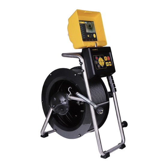
Introduction vCamMX-2+ Series Control Module Overview The vCamMX-2+ control module records and plays back MP4 videos and JPEG images. Audio and text comments can be added to the videos and text comments can be added to the JPEG images. The system's time, date, and distance of the deployed pushrod are added to both video and pictures. The following describes the features of the control module: Fuse compartment LCD keypad... - Page 13 Introduction LCD Menu Icons Step Back / ESC Press this Key to return to the previous screen or exit an operation. Karat choice keys Press these keys to select while in various menus. Press this Key when required to complete an action. Enter Press this Key to hide and show the main on-screen menu while viewing and recording.
- Page 14 Introduction vCamMX-2+ Playback Controls, Camera Lights and On-screen Keyboard While the file rename dialog box is on the screen, use the buttons Keyboard corresponding to the top, right, bottom, and left arrows to navigate Navigation through the on-screen keyboard. Navigate to and press the next Key on the on-screen keyboard to save the changes.
-
Page 15: Type-Mx Cable Reel Overview
Introduction Type-MX Cable Reel Overview The Type-MX cable reels are used to store and control the deployment of the pushrod cable. Cable guide Pushrod trace post Sonde Interconnect cable socket Termination spring Horizontal position feet Friction/locking brake LCD swivel Rubber feet Camera head Frame Pushrod... -
Page 16: Control Module Adjustments
Introduction Control Module Adjustments The swivel assembly allows the LCD compartment to rotate approximately 60-degrees rotation left or right from the starting point. Do not rotate the LCD compartment further than 60-degrees left or right from the starting point. Doing so can cause internal damage to the swivel assembly and internal wiring. -
Page 17: Initial Control Module Setup
Initial Control Module Setup 3. Initial Control Module Setup Initial Control Module Setup 3.1.1 Installing the Fuse Install the 10 Amp - 250 Volt fuse in the fuse compartment on the side of the control module. The control module will operate without a fuse when using AC power, but the battery will not charge, and the unit will turn off when the AC power is removed. -
Page 18: Navigating Through The Setup Menu
Initial Control Module Setup Navigating through the Setup Menu 3.2.1 The key used in the setup procedure Step Back / ESC Press this Key to return to the previous screen or exit an operation. Karat choice keys Press these keys to select while in various sub-menus. Press this Key when required to complete an action. -
Page 19: Set The Date And Time
Initial Control Module Setup 3.2.1.4 Set the Date and Time Setting the Date/Time format allows the choice of three date formats and a 12 or 24-hour time format. Date formats available are: MM/DD/YYYY, DD/MM/YYYY and YYYY/MM/DD Time formats available are: 12-hour (08:00 PM) or 24 hours (20:00) 1. -
Page 20: Set The Sonde Frequency
Initial Control Module Setup 3.2.1.6 Set the Sonde Frequency The vCamMX-2+ contains a choice of three sonde frequencies. The user can activate any of the three frequencies or turn off all three. The system has two low frequencies of 512Hz and 640Hz and one high frequency of 33kHz. -
Page 21: Restore The Factory Default Settings
Initial Control Module Setup 3.2.2 Restore the Factory Default Settings Restoring the default settings will erase all the settings on the control module and return it to the factory default. This will not erase any videos or images on the hard drive. 1. - Page 22 Initial Control Module Setup The vCamMX-2+ series firmware updates come as a ".mxip" extension file. The firmware files can be obtained at www.vivax-metrotech.com, an authorized service center, distributor, or a local Vivax- Metrotech office. Only USB devices can be used to perform the update. The firmware update file must be installed on the USB device’s "root directory."...
- Page 23 Initial Control Module Setup 5. Press the on-screen "Update" key to start the firmware update. 6. Let the update run uninterrupted until finished. During the update, the control module will (7a) load the files from the USB device, (7b) update the firmware chip in the control module, (7c) restart, (7d) finish updating the firmware files, then restart and return to the main viewing screen.
- Page 24 Initial Control Module Setup 7. During the update, the control module will reboot twice. Watch the progress indicators and let the system run until it returns to the main viewing screen. (7e) Files Display Lights 8. Confirm that the firmware update was successful by comparing the version after the update to the version number before.
-
Page 25: Video Recording And Image Capture
Video Recording and Image Capture 4. Video Recording and Image Capture Overview This chapter covers video recording, image capturing, reviewing files, and copying, moving and deleting video and picture files. During a video recording, the following options can be used: •... -
Page 26: Taking Jpeg Pictures
Video Recording and Image Capture To change the file name use the Navigation Arrow buttons on the black control box to control the on- screen keyboard. Press the center Enter Key to select each letter. Navigation Arrow buttons Enter button When finished entering the file name, navigate to the Done Key(C) and press the center Enter button (D) to save the file name. -
Page 27: Viewing Recorded Videos And Pictures In The Control Module
Video Recording and Image Capture Viewing Recorded Videos and Pictures in the Control Module 4.3.1 vCamMX-2+ File Manager Overview STORAGE > SD Card NTSC 1016_01pm_4657.mp4 7.7 MB 1016_01pm_4618.jpg 44.2 kB 1016_13_4416.mp4 66.6 kB 1016_13_4355.jpg 66.0 kB 1016_13_4352.jpg 65.1 kB 1016_13_2344.jpg 1016_01pm_4657.mp4 45.1 kB 1016_13_1807.mp4... -
Page 28: Copying Files
Video Recording and Image Capture 4.3.3 Copying files 1. Press the Files Key to enter the file manager. 2. Choose the drive where the files are located, SD or USB. 3. Use the Up/Down Scroll Keys to highlight the desired file(s). 4. -
Page 29: Corrupt Video Files
Video Recording and Image Capture Corrupt Video Files A file typically becomes corrupted when a problem occurs during the recording session, saving the file, or copying or moving the video file. If your control module loses power or crashes as you copy or move a file, there's a good possibility that the file will become corrupted. -
Page 30: Features Available During Recording
Features Available During Recording 5. Features Available During Recording During a video recording, the following options are operational and usable: • Wi-Fi • Sonde • Audio Commenting • On-screen Text writer • Camera LED control • Distance counter reset • Display color adjustments •... -
Page 31: On-Screen Display (Osd Info)
Features Available During Recording 00:00:15 On-Screen Display (OSD Info) The deployed pushrod's distance and the system's current date and time are shown on the screen and recorded in videos and pictures. The color of the OSD info can also be changed to suit the environment inside the pipe being inspected. -
Page 32: From The Lcd Keypad
Features Available During Recording 5.6.2 From the LCD Keypad 1. Press "Lights" to bring up the LED lights sub-menu. 0 7 : 5 0 : 0 2 0 . 0 0 M 0 8 -2 2 -2 0 2 3 Files Display Lights... - Page 33 Features Available During Recording (3 / 5) Page Erase Color Position Figure 1 (3 / 5) ?123 ’ ” English (US) Figure 1a...
- Page 34 Features Available During Recording OSD Sub-menu options OSD (On-Screen Display) – Consists of the system's time, distance count, and date. Color – Changes the text colors from white to black to yellow to green to red, then back to the default color of white. Position –...
-
Page 35: Jpeg Image Capture
Features Available During Recording The on-screen keyboard will never appear in any videos or pictures. Use the pause key to pause the video while entering text. When finished, press pause again to resume recording. Use the Stop key to hide and show the current page of the text. Status bar page information: (2 / 2) 1. -
Page 36: Wi-Fi
Wi-Fi 6. Wi-Fi Wi-Fi Connection for Apps The vCamMX-2+ control module has built-in Wi-Fi that broadcasts an SSID (secure network name) and uses DHCP (the protocol that assigns an IP address needed to connect to the control module) to assign IP addresses to a tablet or smartphone running the VMC app. When connected to the VMC app, the control module's video stream is transmitted. -
Page 37: Using The Reel
Using the Reel 7. Using the Reel Pushrod Overview The Pushrod Cable comprises a fiberglass rod surrounded by wire conductors and a Kevlar braid coated with a thick polypropylene jacket. Because of the harsh environment in which the pushrod is used, care should be taken to keep it in good operating condition. -
Page 38: Deployment Of The Pushrod Cable
Using the Reel The sonde cup (a) in the cable guide at the 12 O’clock position 5. Power on the control module. When the control module starts, it will see the position of the sonde cup as “zero.” 7.1.2 Deployment of the Pushrod Cable The friction brake should always be partially applied to slow cable deployment. - Page 39 Using the Reel Before deploying the Pushrod, you should: a) Remove any standing water from the pipe. The images will be much better if the camera head is not underwater. b) Remove debris and objects from the pipe first. The camera is made to inspect the insides of pipes and not to clear or unblock them.
- Page 40 Using the Reel When accessing a “T” entry, use a string to bend the camera head and point it in the desired direction in the T. Be extra careful in T entries not to fold the camera back on itself; this could cause the camera to get stuck in the pipe.
-
Page 41: Camera Heads And Terminations
Camera Heads and Terminations 8. Camera Heads and Terminations Parts of the Camera Heads D18-HD and D26-HD Cameras for the Type-MX Mini Reel Polycarbonate LED cover Sapphire glass lens Camera Head Face Groove for skid setscrews Camera housing Camera Head Body Interior threads Gold contact pins Circuit board... -
Page 42: Spring Termination Parts
Camera Heads and Terminations Camera Head Options for the Type-MX Mini Reel Camera Heads Leveling Description Pipe Size Range 1.5” to 3” / 38mm to Non-leveling 18mm / 0.76” diameter 75mm D18-HD Self-Leveling 26mm / 1” diameter 2” to 4” / 50 to 100mm D26-HD Contact a local Vivax-Metrotech distributor or local office for ordering information, applications, compatibility, and pricing. -
Page 43: Pre-Checking The Camera Glass Lens And Led Cover
Camera Heads and Terminations 8.2.4 8.2.4 Pre-checking the Camera Glass Lens and LED Cover Pre-checking the Camera Glass Lens and LED Cover This pre-check is better done with a control module attached to a reel or by the camera test port. For this pre-check, the LED lights should be on so that the camera face can be better examined. - Page 44 Camera Heads and Terminations Camera head removal 1. Use the section of the tool labelled TERM KIT to hold the flats on the spring. 2. Place the section of the other tool labelled D26-HD or D20-HD on the camera head flats and turn counterclockwise until the camera is loosened.
-
Page 45: Removing And Installing The Spring Assembly
Camera Heads and Terminations Removing and Installing the Spring Assembly Don’t touch the green circuit board, gold pins on the spring sonde assembly, or camera head with bare hands. Touching these will transfer oils from the fingers to these components, leading to premature corrosion. -
Page 46: Camera Skids
Camera Skids 9. Camera Skids Camera Skids Camera skids are devices that attach to the camera head to 1) keep the camera head off the floor of the pipe to help avoid pushing up debris and dirt, which will end up on the camera lens, blocking your view, and 2) allow the camera LED lighting to function better by keeping the lights more centered in the pipe allowing a more even spread of light on the pipe walls and ahead and 3) protect the camera head by giving a shoveling effect which allows the camera head to be lifted over offsets and objects... -
Page 47: Standard Skids, Two-Part Clip Together
Camera Skids Apply a layer of electrical tape over the screw holes on the installed skid. This will help keep debris from filling the screw slot, making removing them easier. 9.2.2 Standard Skids, Two-part Clip Together D26-HD Tools Needed: No tools are needed 1. -
Page 48: Guide Skids, Clamp Around The Camera Head
Camera Skids 5. Press the two skid halves together until the tabs lock into the receptacles. 9.2.3 Guide Skids, Clamp around the Camera Head Some vCam series skids will come with a removable rubber front guard. The removable rubber front protects the camera;... -
Page 49: Locating The Camera Sonde And Pushrod
Locating the Camera Sonde and Pushrod 10. Locating the Camera Sonde and Pushrod Always “Call Before You Dig” and follow your company’s safety practices and local, state, and national regulations. The Type-MX reel includes a locatable sonde in the termination assembly and a contact post on the reel for tracing pushrod with an external transmitter. - Page 50 Locating the Camera Sonde and Pushrod 5. Turn on the utility locator transmitter and select a frequency. We recommend using a higher frequency, such as 65kHz or 83kHz. Ensure that the transmitter has good ground. The better the ground, the better the locator will perform. 6.
-
Page 51: Troubleshooting
Troubleshooting 11. Troubleshooting Please check the Knowledge Center on the Vivax-Metrotech website for the latest support information. Go to www.vivax-metrotech.com and then click Support, then Knowledge Center. Problem: No power. The unit will not turn on: Check: 1. Check to see if the fuse is installed, blown, or damaged. The unit will not charge your battery if the fuse is not installed. - Page 52 Troubleshooting Problem: Interference or noise on LCD: Check: In some circumstances, the Sonde can cause interference in the video being viewed or recorded. The Sonde is recommended to be turned off unless it is being used for location. Problem: USB or SD device not recognized: Check: 1.
- Page 53 Illustrations used in this manual's preparation will inevitably show some resemblance to similar images from other manufacturers. These manufacturers have permitted the use of their graphics, and this statement is intended to attribute such credit. ® The Bluetooth word mark and logos are registered trademarks owned by Bluetooth SIG, Inc. iOS is a Cisco Systems, Inc.
- Page 55 Vivax-Metrotech Corporation 3251 Olcott Street, Santa Clara, CA 95054, USA Toll-Free: 1-800-446-3392 Phone: +1 (408) 734-3880 Website: www.vivax-metrotech.com Online Manual © 2024 Vivax-Metrotech Corporation...
Need help?
Do you have a question about the vCamMX-2+ and is the answer not in the manual?
Questions and answers