Vivax Metrotech vCamMX-2 User Handbook Manual
Hide thumbs
Also See for vCamMX-2:
- Training (67 pages) ,
- Quick setup manual (2 pages) ,
- Quick setup manual (2 pages)
Table of Contents
Advertisement
Quick Links
Advertisement
Table of Contents
Troubleshooting

Related Manuals for Vivax Metrotech vCamMX-2


Summary of Contents for Vivax Metrotech vCamMX-2
- Page 1 User Handbook (English Edition) Version 1.0 P/N:4.04.000132...
-
Page 3: Table Of Contents
Camera Head Serial Number Location......................2 Firmware Revision Location............................2 Request for Service.................................3 Distributors and Service Centers..........................4 Introduction....................................5 The vCamMX-2 Inspection Camera System ......................5 What’s in the box................................5 vCamMX-2 Series Control Module Overview......................6 Type-MX Cable Reel Overview.............................8 Initial Control Module Setup..............................9 Initial Control Module Setup............................9 4.1.1... - Page 4 Viewing Recorded Videos and Pictures in the Control Module................17 5.3.1 vCamMX-2 File Manager Overview......................17 5.3.2 Viewing and playing contents of the USB drive or SD Card..............17 5.3.3 Copying files..............................17 5.3.4 Deleting files..............................18 Troubleshooting Video Playback..........................18 AVI Video Format................................18 Getting Codecs................................18 File Associations................................18 Other Media Players..............................19 Features Available During Recording...........................21...
- Page 5 10.2.2 Guide Skid Installation..........................37 10.2.3 Removable Rubber Guard Skids.......................38 Locating the Camera Sonde and Pushrod........................39 11.1 Introduction..................................39 11.2 Applying a Locate Signal onto the Pushrod......................39 11.3 vLoc3-Cam Sonde and Camera Locator......................40 11.4 VM-540 Sonde and Camera Locator........................42 Accessories.....................................46 12.1 Skid Range..................................46 12.2 Accessories.................................46 12.3...
-
Page 7: General Safety Instructions
General Safety Instructions General Safety Instructions Health and Safety This equipment is primarily used for the inspection of sewer pipes, by professionals operating in the sewer and plumbing industry, and maintained by professionals familiar with the health risks of maintaining equipment that has been in a sewer. Such professionals will be protected by their own company’s recommendations and work practices. -
Page 8: Service & Support
The control module assembly consists of two major parts. They are the LCD assembly and the control box assembly. The serial number for the vCamMX-2 control module is found on the back of the control box. The control module’s serial number label is on the back of the black control box. -
Page 9: Request For Service
Service & Support To view the control modules current firmware version, follow these steps: Press the “Setup” key to bring up the sub-menu. Press the “System” key to enter the system sub-menu. The firmware revision is shown on the top line on the left side of the word “Version”. Request for Service In the event that any of the system components need servicing the more concise information provided will result in a quicker turnaround time. -
Page 10: Distributors And Service Centers
Service & Support Distributors and Service Centers World Headquarters, United State of America Central/South America and the Caribbean Vivax-Metrotech Corporation Ventas para América Latina 3251 Olcott Street, 3251 Olcott Street, Santa Clara, CA 95054, USA Santa Clara, CA 95054, USA Website : www.vivax-metrotech.com T/Free : 800-624-6210... -
Page 11: Introduction
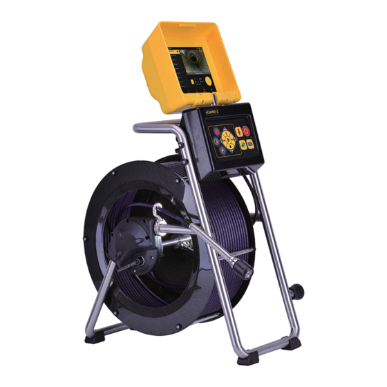
Introduction Introduction The vCamMX-2 Inspection Camera System The vCamMX-2 Inspection Systems consist of three major components: vCamMX-2 Control Module, Type-MX Reel with Pushrods, and Camera Heads. What’s in the box vCamMX-2 Control Module SD Card Type-MX Reel with pushrod USB Thumb drive... -
Page 12: Vcammx-2 Series Control Module Overview
Series Control Module Overview The vCamMX-2 control modules allows for the viewing, recording and playback of Audio Video Interleave (AVI) format video as well as image capturing of Joint Photographic Experts Group (JPEG) pictures. Audio and text commentary can be added to the videos and text commentary can be added to the captured pictures. - Page 13 While playing a video: Use these buttons to Pause, Forward Fast, Stop and Rewind the video playing. Playback controls and Camera lights vCamMX-2 Playback Controls, Camera Lights and On-screen Keyboard While the file rename dialog box is on the screen, use the buttons corresponding to Keyboard Navigation the top, right, bottom and left arrows to navigate through the on-screen keyboard.
-
Page 14: Type-Mx Cable Reel Overview
Introduction Type-MX Cable Reel Overview The Type-MX cable reels is used to store and control the deployment of the pushrod cable. Cable guide Cable drum Sonde Pushrod Reel Connection Hub Termination spring Interconnect Cable Socket Friction and locking brake Horizontal Position Feet Rubber feet Camera head Frame... -
Page 15: Initial Control Module Setup
Initial Control Module Setup Initial Control Module Setup Initial Control Module Setup 4.1.1 Installing the Fuse Install the 10 Amp - 250 Volt fuse in the fuse compartment on the side of the control module. The control module will operate without a fuse when using AC power but the battery will not charge and the unit will turn off when the AC power is removed. -
Page 16: About Control Module Settings
About Control Module Settings After the initial setup of the vCamMX-2 control module is done all the settings selected are saved into the control module’s memory and will remain until changed. Note that the settings will be lost if the unit is reset to factory defaults. -
Page 17: Set The Date And Time
4.2.1.5 Set the Storage Options The default drive for the vCamMX-2 is USB. If no USB drive is inserted the system will record to the SD drive. If neither SD nor USB is present the system will not record. -
Page 18: Set The File Rename Option
(on). Press the ESC key to return to the Setup sub-menu, press again to return to the main viewing screen. 4.2.1.9 Set up Wi-fi The built in Wi-fi option allows the vCamMX-2 to connect to smartphones and tablets. A free app for the vCamMX-2 is available for download from the Apple Store. Press the Setup key to bring up the sub-menu. Press the Features key to enter the features sub-menu. -
Page 19: Update The Control Module Firmware
Initial Control Module Setup 4.2.4 Update the Control Module Firmware The vCamMX-2 series firmware updates come in the form of an “.mxip” extension file. The firmware files can be obtained at www.vivax-metrotech.com, authorized service center, distributor or a local Vivax-Metrotech office. Only USB devices can be used to perform the update. The firmware update file must be installed on the USB devices “root directory”. Specifically, the files must be visible when viewing the contents of the USB device. WARNING Do not interrupt the update once it has started. - Page 20 Initial Control Module Setup Press the “System” key to enter the system sub-menu. Region Storage Features Use the “Up/Down” scroll keys to highlight the firmware update file. Make a note of the current firmware version in the control module. It is shown to the right of the word “Version”. Press the on-screen “Update” key to start the firmware update.
- Page 21 Initial Control Module Setup Let the update run un-interrupted until finished. During the update the control module will (7a) load the files from the USB device, (7b) update the firmware chip in the control module, (7c) restart, (7d) finish updating the firmware files then restart and return to the main viewing screen. During the update the control module will reboot twice. Watch the progress indicators and let the system run until it returns to the main viewing screen.(7e) Files Display...
-
Page 22: Video Recording And Image Capture
Video Recording and Image Capture Video Recording and Image Capture Overview This section of the manual covers video recording, capturing images, reviewing videos and pictures, and copying, moving and deleting video and picture files. During a video recording the following options are operational and usable: •... -
Page 23: Viewing Recorded Videos And Pictures In The Control Module
Video Recording and Image Capture Viewing Recorded Videos and Pictures in the Control Module 5.3.1 vCamMX-2 File Manager Overview STORAGE > SD Card NTSC 1016_01pm_4657.avi 7.7 MB 1016_01pm_4618.jpg 44.2 kB 1016_13_4416.avi 66.6 kB 1016_13_4355.jpg 66.0 kB 1016_13_4352.jpg 65.1 kB 1016_13_2344.jpg 1016_01pm_4657.avi... -
Page 24: Deleting Files
Video Recording and Image Capture 5.3.4 Deleting files Follow steps 1 through 4 in section 5.3.3 Copying Files. Press the Delete key to delete the file(s). WARNING Do not remove the SD or USB device from the control module while copying or moving files to them. This may result in corrupt un-playable files being created and a risk of corrupting the original file on the hard drive. -
Page 25: Other Media Players
Video Recording and Image Capture Select Windows Media Player. If Windows Media Player is not shown on the list of available software, you will have to select “Choose Default Program” in the bottom right corner. Select “Windows Media Player” here. Make sure the “Always use the selected program to open this kind of file” box is checked. - Page 26 Video Recording and Image Capture NOTE Vivax-Metrotech does not provide technical support for any of these players or Windows Media Player. Consult the manufacturer or your local IT department for technical support. Vivax-Metrotech has manufactured the vCam-6 control module to produce video files and jpeg pictures that are compatible with the various Windows operating systems from Windows XP and later versions.
-
Page 27: Features Available During Recording
Features Available During Recording Features Available During Recording During a video recording the following options are operational and usable: • Wi-Fi • Sonde • Audio Commenting • On-screen Text writer • Camera LED control • Distance counter reset • Display color adjustments •... -
Page 28: On-Screen Display (Osd Info)
Features Available During Recording 00:00:15 On-Screen Display (OSD Info) The current time, date and distance of pushrod deployed can be shown on the screen and can be recorded in videos and pictures. The color of the OSD info can also be changed to suit the environment inside the pipe being inspected. By default the OSD is positioned at the bottom of the screen and in white text. -
Page 29: From The Lcd Keypad
Features Available During Recording 6.6.2 From the LCD Keypad: Press “Lights” to bring up the LED lights sub-menu. 0 7 : 5 0 : 0 2 0 . 0 0 M 2 0 1 8 - 0 8 - 1 7 Files Display Lights... - Page 30 Features Available During Recording OSD Sub-menu options OSD (On-Screen Display) – Consists of the system’s time, distance count, and date. Color – Changes the text colors from white to black to yellow to green then back to the default color of white. Position –...
- Page 31 Features Available During Recording (3 / 5) ?123 ’ ” English (US) Figure 1a Navigating the on-screen keyboard Up/Down keys – Use these keys to navigate up and down on the on-screen keyboard. Left/Right – Use these keys to navigate left and right on the on-screen keyboard.
-
Page 32: Jpeg Image Capture
Features Available During Recording Tip: Use the pause key to pause the video while entering text. When finished entering text press pause again to resume recording. Use the Stop key to hide and show the current page of text. Status bar page information: (2 / 2) In this figure, the upper right hand corner shows the page status page 2 of 2 pages. -
Page 33: Wi-Fi And Ethernet
Wi-Fi Connection for Apps The vCamMX-2 Control Module has built in Wi-Fi that broadcasts an SSID (secure network name) and uses DHCP (the protocol that assigns an IP address needed to connect to the control module) to assign IP addresses to a tablet or smartphone. -
Page 34: Cable Reels
Using the Cable Reel The vCamMX-2 system comes as a complete system with control module attached or with just the Type-MX reel only and used with other vCam series control modules. When the unit ships as a reel only, an interconnect cable which plugs into other vCam series control modules is provided. -
Page 35: Deployment Of The Pushrod Cable
Cable Reels Insert Sleeve 8.1.3 Deployment of the Pushrod Cable WARNING The friction brake should always be partially applied to slow down cable deployment. To avoid injury, great care should be taken when stopping the cable from unwinding. Do not wear loose clothing that can become caught in a spinning reel. Keep hands away from a spinning reel. - Page 36 Cable Reels Use the Insertion Sleeve as much as possible to prevent the pushrod from rubbing on sharp surfaces. Use devices such as a Tiger Tail when the point of entry makes it impossible to use the Insertion Sleeve such as inspecting lines in a manhole. Insert Sleeve Insert Sleeve in cleanout Use “grip”...
- Page 37 Cable Reels Use a skid on the camera head. A skid will not only protect the camera head from directly hitting debris and offsets, it will also keep the camera head off the floor of the pipe and better centered within it. Keeping the camera head off the floor of the pipe will also improve the picture quality, because the light from the camera will be more evenly spread in the pipe. Various types of skids are available for different applications.
-
Page 38: Camera Heads And Terminations
Camera Heads and Terminations Camera Heads and Terminations Parts of the Camera Heads D18-MX and D26-MX Cameras for MX Mini Reel Camera Head Face Sapphire glass lens Polycarbonate LED cover Camera Head Body Groove for skid setscrews Camera housing Camera Head Rear Interior threads Gold contact pins Circuit board... -
Page 39: Spring Termination Parts
Camera Heads and Terminations D26-MX NTSC (USA) 2 to 4 inches MX Mini Reel D26-MX D26-MX PAL (Europe) 50 to 100mm Self-Leveling 26mm / 1” diameter Contact a local Vivax-Metrotech distributor or local office for ordering information, applications, compatibility and pricing. -
Page 40: Pre-Checking The Camera Glass Lens And Led Cover
Camera Heads and Terminations 9.2.4 Pre-checking the Camera Glass Lens and LED Cover This pre-check is better done with a control module attached to a reel or by the camera test port. For this pre-check, the LED lights should be on so that the camera face can be better examined. Pre-checking the LED Cover The Polycarbonate LED cover is the section of the face of the camera that covers the LEDs. -
Page 41: Removing And Installing The Mx Spring Assembly
Camera Heads and Terminations Hold the termination spring close to the base of the camera head. Present the camera head to the spring. Screw on the camera head by turning it in the clockwise direction. Screw on until the O-Ring is no longer visible. Hand tighten the camera head. -
Page 42: Camera Skids
Camera Skids 10. Camera Skids 10.1 Camera Skids Camera skids are devices that attach to the camera head to 1) keep the camera head off the floor of the pipe, to help avoid pushing up debris and dirt on which will end up on the cameras lens blocking your view, 2) allow the camera LED lighting to function better by keeping the lights more centered in the pipe allowing a more even spread of light on the pipe walls and ahead and 3) provide protection to the camera head by giving a shoveling effect which allows the camera head to be lifted over offsets and objects which helps prevent the camera head from making direct contact with them. -
Page 43: Guide Skid Installation
Camera Skids NOTE Do not over tighten the setscrews. This may result in striping the screw threads or damage to the camera housing. Apply a layer of electrical tape over the screw holes on the installed skid. This will help keep debris and soil out of the screw slots making it easier to remove. -
Page 44: Removable Rubber Guard Skids
Camera Skids NOTE Do not over tighten the setscrews. This may result in damage to the camera housing. 10.2.3 Removable Rubber Guard Skids Some of the vCam series skids will come with a removable rubber front guard. The removable rubber front is meant to protect the camera it should make direct contact with objects such as offsets. -
Page 45: Locating The Camera Sonde And Pushrod
Locating the Camera Sonde and Pushrod 11. Locating the Camera Sonde and Pushrod 11.1 Introduction The Type-MX reel includes a locatable sonde located at the base of the spring termination assembly. The controls for the sonde are located on the front panel of the control module. The Type-MX reel includes the option to trace the entire length of pushrod. -
Page 46: Vloc3-Cam Sonde And Camera Locator
Locating the Camera Sonde and Pushrod Sonde Locating The best practice for locating the camera sonde is to push the camera into the pipe and when it is level stop and do the locate. From this point on work in 10 to 20 foot increments stopping every 10 to 20 feet and locate the sonde. It is not a good practice to just push the camera into the pipe a great distance away and set out to locate it. - Page 47 Locating the Camera Sonde and Pushrod Press the “f” key to select the sonde frequency being used. Hold the locator vertically and stationary with the tip on the ground. If the locator is within the range of the sonde the screen will appear similar to the one below with an arrow pointing in a particular and steady direction.
-
Page 48: Vm-540 Sonde And Camera Locator
Locating the Camera Sonde and Pushrod Overview 11.4 VM-540 Sonde and Camera Locator VM-540 Receiver Display Battery Level Indicator Speaker Volume Indicator Signal Strength Percentage Selected Sonde Frequency Signal Strength Indicator Sensitivity Setting Indicator VM-540 Receiver Controls Reduce Sensitivity Press this key to reduce the amount of signal from the sonde. On/Off Control Long press to switch on/off. - Page 49 Locating the Camera Sonde and Pushrod Changing the Locate Frequency Press and hold the depth measurement/frequency selection pushbutton until the frequency menu is entered. The display will show the present frequency selected in large numbers in the centre of the screen. Use the “+” or “–” pushbuttons to select the desired frequency.
- Page 50 Locating the Camera Sonde and Pushrod Hold the locator above the Sonde at ground level. Adjust the sensitivity of the locator by pressing the “+” or “-” pushbuttons to keep the signal on scale. Rotate the receiver until the maximum signal is detected. NOTE: Moving the locator further left and right will result in detecting smaller “ghost”...
- Page 51 Locating the Camera Sonde and Pushrod NOTE The depth measurement is an approximation. Depth indications can be affected by field distortion caused by interference from in-band signals or metal structures such as rebar. An aid to determining if the depth is correct is to repeat a depth measurement with the locator a known distance (for example 1 foot above the ground) and to note if the depth has increased by this amount.
-
Page 52: Accessories
Accessories 12. Accessories 12.1 Skid Range Model Description & Diameter Picture Available for cameras D18-MX Standard Standard Skid comes with the camera D18-MX D26-MX Standard Standard Skid comes with the camera D26-MX Visit our website at www.vivax-metrotech.com or contact your local distributor to view the full range of accessory skids available. -
Page 53: Troubleshooting
Troubleshooting 13. Troubleshooting Problem: No power, unit will not turn on: Check: Check to see that the fuse is installed, blown or damaged in any way. If the fuse is not installed then the unit will not charge your battery. Try using mains current and not battery to turn on the unit. - Page 54 Notes: Disclaimer: Product and accessory specification and availability information is subject to change without prior notice. Vivax-Metrotech Corporation 3251 Olcott Street, Santa Clara, CA 95054, USA Toll Free: (800) 446-3392 Phone: +1 (408) 734-1400 Website: www.vivax-metrotech.com ™...
Need help?
Do you have a question about the vCamMX-2 and is the answer not in the manual?
Questions and answers