Vivax Metrotech vLoc3-5000 User Handbook Manual
Precision location system
Hide thumbs
Also See for vLoc3-5000:
- User handbook manual (20 pages) ,
- Quick manual (2 pages) ,
- Quick manual (2 pages)
Table of Contents
Advertisement
Quick Links
Advertisement
Table of Contents

Related Manuals for Vivax Metrotech vLoc3-5000


Summary of Contents for Vivax Metrotech vLoc3-5000
- Page 1 User Handbook (English Edition) Version 1.7 P/N:4.04.000106...
- Page 3 General Safety & Care Information Who Can Use This Equipment 5. General Rules regarding Disposal of Batteries • This equipment must only be used by people suitably trained in the use of pipe and • Never disassemble a battery or battery pack. •...
-
Page 5: Table Of Contents
2. vLoc3-5000 Receiver .................................3 2.1 vLoc3-5000 Receiver Overview ............................3 2.2 Charging the Receiver Batteries ............................4 2.3 vLoc3-5000 Receiver Keypad ............................5 2.4 The vLoc3-5000 User Menu ..............................5 2.4.1 Setup - Receiver ..............................5 2.4.2 Setup - Operational ...............................6 2.4.3 Setup - Features ..............................7 2.4.4 Setup - Informational .............................7... - Page 6 6. Using SiS Mode Accessories ..............................54 6.1 Using the SiS (Signal Select ) Clamp ..........................54 6.2 Using the vLoc3-5000 SiS Remote Antenna ........................55 6.3 Using the SiS Mode with the Remote Antenna........................57 7. Accessories & Options ................................61 7.1 Transmitter Signal Clamps ..............................61 7.2 A-frame Fault Locator ..............................61...
-
Page 7: Service & Support
Service & Support 1. Service & Support 1.1 Serial Number and Software Revision Number When requesting product support, always quote your receiver and transmitter model number, serial number, and software revision number. They can be found as follows. Model & Serial Number NOTE Software Revision Number: On both receiver and transmitter, the software revision number is displayed on the LCD during the startup sequence or found in the “About”... -
Page 8: Distributors And Service Centers Closest To You
Service & Support 1.2 Distributors and Service Centers Closest to You: Worldwide Sales Offices and Service Centers World Headquarters, United States of America Central/South America and the Caribbean Vivax-Metrotech Corporation Ventas para América Latina 3251 Olcott Street, Santa Clara, CA 95054, USA 3251 Olcott Street, Santa Clara, CA 95054, USA T/Free : 1-800-446-3392... -
Page 9: Vloc3-5000 Receiver
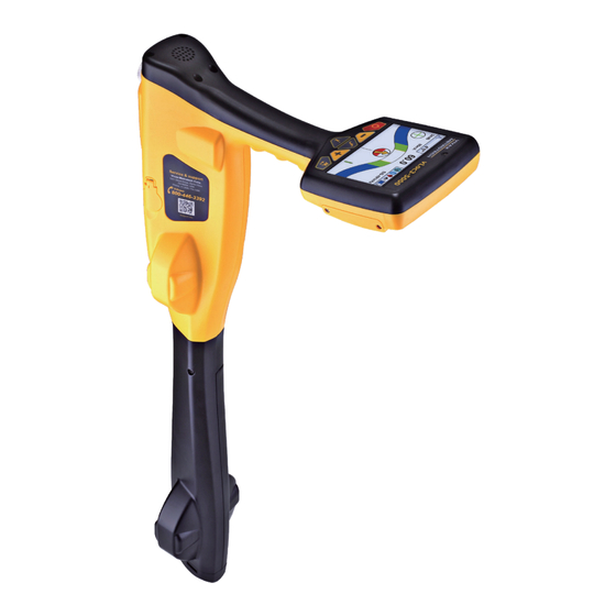
Receiver 2. vLoc3-5000 Receiver 2.1 vLoc3-5000 Receiver Overview The vLoc3-5000 is a Precision Location System designed to meet the needs of utility companies and their contractors. The following describes the features and use of the receiver: What’s in the box:... -
Page 10: Charging The Receiver Batteries
Receiver 2.2 Charging the Receiver Batteries The vLoc3-5000 can be used with either alkaline batteries or an optional rechargeable battery pack. The central illuminated section within the battery icon indicates the amount of charge remaining. • Blue center indicates Alkaline batteries. -
Page 11: Vloc3-5000 Receiver Keypad
Series Keypad Long press = enter the menu 2.4 The vLoc3-5000 User Menu The user-configurable vLoc3 series receivers can be customized to suit the user’s preferences. The receivers have several features that can be switched on and off through the user menu. -
Page 12: Setup - Operational
Receiver Backlight – Press the Enter key to change the backlight intensity to Low, Medium, High, or Auto. The use of the “Auto” selection is recommended because the receiver has a built-in light sensor that automatically adjusts the backlight intensity to the surrounding lighting conditions. -
Page 13: Setup - Features
Receiver Locate Perspective – Enter this menu to select the graphical format that the locate data will be displayed. These displays are described further in the manual. The options are: Locate Perspective Classic Locate Vector locate Transverse graph Plan view Sonde 2.4.3 Setup - Features... -
Page 14: Warnings And Alerts
Receiver 2.5 Warnings and Alerts Warning symbols are shown on the display and accompanied by an audible sound and vibration in the handle unless configured otherwise in the MyLocator3 desktop app. Warnings can also be switched off in the setup menu. - Page 15 Receiver Once the option is selected, the receiver will automatically assess the user’s preselected frequencies. The receiver will scan all available frequencies and display a progress bar and the list of frequencies assessed will be displayed. The frequency under test is shown on the top line.
-
Page 16: Vloc3 Series Locate Modes And Screens
- Transverse Plat Locate - Sonde Locate The vLoc3-5000 receiver gives the user a choice of two Classic Locate screens. They are the vLoc3-5000 classic screen and the vLoc3-Pro classic screen. This manual will first explain the functions of the “Classic Screens” as familiarity of these screen will help understand the functions of the others. -
Page 17: The Classic Screen
Receiver 2.5.5 The Classic Screen The vLoc3-5000 Classic Screen has all the functions normally seen on a classic cable locator. The main functions are: 60.0 0.39m 24dB 68mA SIS-491kHz Percentage signal strength (mirrors the bar graph setting) Gain setting Only visible with SiS frequencies, “+”... -
Page 18: Classic Locating Modes (Response)
Receiver 2.6 Classic Locating Modes (Response) The vLoc3-5000 receiver has an array of six antennas, and these can be toggled through different configurations (modes) to provide different responses to the signals radiating from buried utilities. The modes are: 2.6.1 Peak Response Mode Two horizontal antennas provide a “Peak”... -
Page 19: Delta Null
Receiver 2.6.4 Delta Null This uses dual vertical antennas. This has the advantage that it provides a sharper response than the “null” mode and is less affected by distorted fields. All other functions are the same as the “Null”... -
Page 20: Alternate Locate Screens
Receiver 2.8 Alternate Locate Screens As previously mentioned, the vLoc3 series receivers have alternative locate screens. The following section describes the operation of these screens. It is left to the user to decide which is the best screen for a particular application. - Page 21 Receiver The color of the confidence circle also changes depending on the degree of confidence: Green: - Low distortion/high confidence. Blue: - Minor distortion/medium confidence, proceed with care. Red: - Excessive distortion/low confidence, treat all data and measurements with caution.
- Page 22 Receiver In addition to the tram lines, the color of the target line also changes depending on the degree of confidence: Green: - Low distortion/high confidence. Blue: - Minor distortion/medium confidence, proceed with care. Red: - Excessive distortion/low confidence, treat all data and measurements with caution.
- Page 23 Receiver Position yourself to one side of the line such that the field markers are just on the screen. You will see that the lines automatically remove themselves after a set period of a few seconds. Clear the screen by pressing the “- ” button. Now walk across the line of the target at a steady pace until you are on the other side of the target line.
-
Page 24: Using The Vloc3-5000
Using the vLoc3-5000 3. Using the vLoc3-5000 3.1 Using the Receiver Line locating using the “Classic” screens. 60.0 1.2m 24dB 68mA SIS-491kHz 3.2 Passive Locating NOTE The compass indicator is not active during passive location. Passive locating refers to the process of detecting signals that “naturally” occur on pipes and cables. These tend to fall into two categories, radio signals and power signals. -
Page 25: Detecting Power Signals
Keeping the vLoc3-5000 vertical, walk across the area to be checked keeping the orientation so that the blade is in line with the direction of walking (see diagram above) If using the Onmi-Peak mode, the orientation of the locator is not important. -
Page 26: Detecting Radio Signals
Locating Radio signals is very similar to detecting Power signals as they are both passive signals. Hold the vLoc3-5000 vertically and away from likely positions of cables or pipes. Adjust the sensitivity control so that the bar graph reading is just starting to show some movement. Now follow the procedure described above in the Power mode section. -
Page 27: Signal Clamp (For Frequencies Above 8Khz)
Using the vLoc3-5000 WARNING Only authorized personnel should make connections to cables. To make a direct connection, insert the direct connection connector to the transmitter. Insert the ground stake into the ground a few meters perpendicular to the line. Connect the black lead to the ground stake. Now take the red lead and connect to the target line. - Page 28 Using the vLoc3-5000 When clamping around a cable make sure the clamp is placed below the grounding point and the two halves of the clamp are completely closed, as shown below. When applying a clamp close to a grounding point where multiple grounds or a grounding bus exists, ensure that you place the clamp around the target line and not to the ground bus/other grounds This will help focus the applied signal to the target line.
-
Page 29: Induction For Frequencies Above 8Khz
With no direct connection lead or signal clamp connected, the transmitter will automatically start to radiate a signal around the transmitter. These signals will penetrate the ground and couple onto buried lines. The signal will then travel along the line which can be detected with the vLoc3-5000 locator. Applying an induction signal to a line. -
Page 30: Locating Active Signals
Using the vLoc3-5000 3.4 Locating Active Signals These instructions assume that the Classic Screen is selected and Peak with Arrows mode is selected for the antenna configuration. With a transmitter, apply an active locate signal to the line. Set the receiver to Peak with Arrows Match the frequency of the receiver to that of the transmitter. -
Page 31: Searching (Sweeping) An Area In The Peak Mode
Using the vLoc3-5000 3.5 Searching (sweeping) an Area in the Peak Mode Buried utilities may be parallel to each other and frequently they cross the area being searched at various angles and depths. As the locator antennas response is directional (using the traditional screen), it is important to search the area in the same or similar pattern as shown. -
Page 32: Distorted Fields
Using the vLoc3-5000 When taking a depth reading the signal current value will also be displayed. This feature is useful for confirming that the detected signal is radiating from the correct line. If the signal is bleeding off onto other services these signals will generally be less than that of the originating signal. -
Page 33: Sonde-Location Mode
Using the vLoc3-5000 3.10 Sonde-Location Mode A Sonde is typically used for locating non-metallic pipes or ducts or the camera end of a sewer inspection camera. Low- frequency versions (512Hz/640Hz) can transmit through some metallic pipes such as cast iron pipes which is why they are frequently used with sewer inspection cameras. -
Page 34: Signal Direction Precision Identification
Using the vLoc3-5000 65.3 2.1m 25dB 640Hz If the bar graph is not steady, it will most likely be because the sonde is not within range. In this case, hold the locator at approximately 45 degrees to the ground and rotate the locator around a full 360 degrees around you. - Page 35 Using the vLoc3-5000 As a result multiple signals radiate from cables and pipes in the area making it difficult to identify the target line. These return signals are typically traveling in the opposite direction than the applied signal. The Signal Direction feature identifies which direction the signal is flowing and hence the target line.
-
Page 36: Signal Select (Sis)
Using the vLoc3-5000 233mA 50°42′59.90570′′N 27.50m 3°26′35.54358′′W 0.78m 233mA • Continue to locate, pinpoint and trace. NOTE If several lines are commonly bonded, the signal direction will carry through to the other lines. This is useful for locating multiple line installations. - Page 37 Using the vLoc3-5000 Signal strength Bleed-off line Target line Signal Select Sample Scenario Distortion Alert Distortion creates phase anomalies in the signal, which can be detected at the receiver and compared to a phase reference imprinted at the transmitter. This reference is set by Signal Select modulation for every SIS transmitter active frequency. The transmitter must be in direct (conductive) connection mode and a Select Signal mode selected (signal clamps can be used but require synchronization, see the section below).
- Page 38 Using the vLoc3-5000 The information screen will show a signal select reset icon over the “return” key. Press the “Return” key to synchronize the equipment. The screen will also revert to The locate screen. Notice the compass arrow will now be pointing forward, and the distortion meter should be empty.
-
Page 39: Data Logging
Data Logging 4. Data Logging The vLoc3 series receivers have internal storage memory that can be used to store locator data. The records are user-initiated and stored by the user whenever the “+” button is pressed when in the “Information” screen. Data can be stored relating to a standard locate or relating to any of the receiver accessories apart from the Remote antenna accessory. -
Page 40: Bluetooth
Data Logging Delete all logs? Press the “+” key to confirm. Are you sure? Press the “-” key to delete or the “+” key to cancel. Deleting logs..After the deletions are complete, the vLoc3 will return to the locate screen. -
Page 41: Fitting The Bluetooth Module
Data Logging 4.1.1 Fitting the Bluetooth Module Turn the receiver off and remove the battery pack. With a small cross-head screwdriver remove the two screws of the module cover and remove the cover. Remove screws Remove cover The slot on the left is for the Bluetooth module. The slot on the right is not active and for future developments. Carefully slide the Bluetooth module slide it into the slot and press with your thumb to secure it in the slot. -
Page 42: Transferring Data From The Vloc3 Receiver To A Computer
Data Logging 4.3 Transferring Data from the vLoc3 Receiver to a Computer One method of transferring data is to use the vLoc3 Series Configurator Tool "MyLocator3". This free desktop program can be downloaded from the Vivax-Metrotech website. MyLocator3 Another method to access the locator data is by using the VMMap App which will store all the locator's data in the web portal. -
Page 43: Application Update
Data Logging The MyLocator3 Start Page MyLocator3 can be viewed in several language options. Click on the pull-down menu to select the desired option. 4.3.2.2 Application Update Every time the MyLocator3 Application is started, its version number is checked against the latest version available on the Vivax- Metrotech server. -
Page 44: Locator Firmware Update
Data Logging 4.3.2.3 Locator Firmware update Each time a locator is connected to the PC, its firmware version is checked against the latest version available on the Vivax- Metrotech server and the user is notified if an update is available, as shown below. This feature will only be available if the computer is connected to the internet. -
Page 45: Data Logging
Data Logging 4.3.4 Data Logging Clicking on the Data Logging tab will display information about the state of the attached locator’s data log contents. The data log contents can be stepped though by using the controls on the right-hand side. The user can upload a selection of logs from the locator to the PC using the upper right-hand side controls. -
Page 46: Splash Screen
Data Logging 4.3.5 Splash Screen In this section, an image can be loaded as a splash screen when the locator is turned on. The locator has an LCD screen with a resolution of 480 by 272 pixels. The image loaded into MyLocator3 will be scaled to fit the width of the screen. If the scaled image height is less than the LCD height, then the image is centered vertically, and white bars are used as padding. -
Page 47: Frequencies Page
Data Logging 4.3.6 Frequencies Page The “Frequencies” page allows the user to select which frequencies and modes are available when the locator's F-key is pressed and which frequencies appear on the locator's menu. The Frequency page list 4.3.7 Menu Settings The “Menu Settings”... -
Page 48: Advanced Features
Data Logging 4.3.8 Advanced Features The Advanced Features are available to those users in possession of a USB security dongle. If a dongle is attached to the PC, its level will be displayed on the MyLocator3 status bar. Three levels of security come with the dongle. Level one is for the end-user supervisors, level two for Vivax-Metrotech's distributors, repair centers, managers, and level three for Vivax-Metrotech use only. -
Page 49: Loc3-10Sistx Transmitter
Loc3-10SiSTx Transmitter 5. Loc3-10SiSTx Transmitter 5.1 Loc3-10SiSTx Transmitter Overview The Loc3-10SiSTx transmitter is a rugged portable transmitter powered by alkaline “D” cells or Li-ion rechargeable batteries. The following describes the features and uses of the transmitter. Loc3-10SiS Transmitter Ground stake Direct connection lead 12 x D cell alkaline batteries Alkaline battery tray... -
Page 50: Transmitter Information Pushbuttons
Loc3-10SiSTx Transmitter 5.1.3 Transmitter Information Pushbuttons Press the “i " button to access the transmitter settings and menu. Use the “+” and “–” buttons to navigate the settings and menus. Use the “f ” button to make selections. An X will appear for selected items. About Frequency Menu Receiver Link Disabled... -
Page 51: Transmitter Batteries - Li-Ion And Alkaline
Loc3-10SiSTx Transmitter 5.2 Transmitter Batteries – Li-ion and Alkaline The 10-watt transmitter uses 12 x D alkaline cell batteries. An optional Li-ion battery tray is available as an accessory. On all transmitters the battery status is shown on the transmitter's LCD. The letters “LP” will appear when the battery status reaches only one bar. -
Page 52: Removing And Installing The Battery Tray
Loc3-10SiSTx Transmitter 5.2.2 Removing and Installing the Battery Tray These procedures apply to both the Alkaline and Rechargeable battery tray. Removing the battery tray 1. Reach under the catch and pull to 2. Lift the catch and repeat for all four 3. -
Page 53: Clamp Mode
Loc3-10SiSTx Transmitter Wherever a direct connection can be safely made without the risk of injury, damage to the customer’s plant, or the transmitter, it is the best way of applying the transmitter’s signal. The positioning of the ground connection can also influence the degree of coupling experienced. Ground connections generally should not be made to other pipes or cables or above ground metallic structures such as wire fences. -
Page 54: Transmitter Frequencies
Loc3-10SiSTx Transmitter “Induction” mode is generally used when no access is available to make a direct connection or a clamp connection. When using induction, likely, the signal being induced onto the target line will also be induced onto other lines in the area and onto above-ground features such as wire fences. -
Page 55: Most Used Frequencies (Frequency Selection) Feature
Loc3-10SiSTx Transmitter The transmitter will always revert to first level output when switched on as a power-saving feature. In most circumstances, this output level is sufficient. Increasing the output power unnecessarily will reduce battery life. All other settings remain the same as the last setting used. -
Page 56: Multi-Frequency Mode For Direct Connection
Loc3-10SiSTx Transmitter Frequency Menu SD-USA Once the wanted frequency is inside the box, press the “f” pushbutton to select FF Low or deselect the frequency. An “x” will appear in the box for a selected frequency. FF High 5 and 10-Watt Transmitters After selecting the frequencies, press the “i”... -
Page 57: Transmitter Link (Tx-Link)
Loc3-10SiSTx Transmitter 5.5 Transmitter Link (TX-Link) Currently the Tx-Link feature is only available in the 5-watt and 10-watt transmitters. The Loc3 series transmitters can be remotely operated from the receiver. This option requires the Transmitter (radio) Link to be installed in both the vLoc3 series receiver and the Loc3 series transmitter. Tx-Link is a factory fit option that must be purchased at the time of ordering. - Page 58 Loc3-10SiSTx Transmitter Menu Imperial/Metric Meter Continuous Information Depth & current Auto Power Off Never Warnings Bluetooth Pairing While the icon on the transmitter is flashing, indicating that it is waiting Transmitter Link to connect to a receiver, switch on the vLoc3 series receiver and enter Transmitter Control the user menu by pressing and holding the information button.
- Page 59 Loc3-10SiSTx Transmitter The various indications of the status are listed below: No radio module or it is disabled (Always disable in the User Menu when not in use) No link and no signal No link and poor signal No link but good signal Is linked to the transmitter, but the signal is poor Is linked to the transmitter with a good signal While the Transmitter and Receiver are linked, changing the Receiver Frequency will automatically...
-
Page 60: Using Sis Mode Accessories
Using SiS Mode Accessories 6. Using SiS Mode Accessories The SiS Clamp and SiS Remote Antenna are two accessories that use the SiS mode. 6.1 Using the SiS (Signal Select ) Clamp The Signal Select Clamp is a precise way to apply the locating signal if direct connection is not possible. Signal Select is a special modulation placed on the targeted utility line, to support positive line identification. -
Page 61: Using The Vloc3-5000 Sis Remote Antenna
3.12 “Synchronizing”. Used in conjunction with the vLoc3-5000 receiver, the Signal Select feature becomes a powerful tool in aiding accurate cable identification. At the receiver, a positive (+) icon appears on the operational interface if the operator correctly identifies and traces the line. - Page 62 120dB 65.5kHz Ensure the frequency selected on the vLoc3-5000 is the same as selected on the transmitter. Place the stethoscope on each of the suspected target cables, if possible part each one from the bunch before each test, with the flats of the antenna in line with the route of the cable.
-
Page 63: Using The Sis Mode With The Remote Antenna
Note the signal reading of each cable. The one with the largest reading is likely to be the target cable. 10. If necessary, adjust the sensitivity of the vLoc3-5000 so that the signal is within the operating section of the bar graph. - Page 64 Using SiS Mode Accessories Method: Apply the signal using the direct connection method. Remember to isolate the cable beforehand as below. It is also preferable to use the ground stake as an independent ground. Using the station ground may result in multiple signals as the signal will return along commonly bonded cables.
- Page 65 Using SiS Mode Accessories Now press the “Return” key. The screen should now show something similar to the below with the “+” icon showing and little or no red shown in the distortion indicator. 52.1 25dB SiS8440 The system is now ready to identify the cable at the location of interest. Identifying a cable Having confirmed the antenna is synchronized with the receiver, proceed to the location the cable is to be identified.
- Page 66 Using SiS Mode Accessories Further confirmation can be achieved by the following: • Run the antenna along the cable with bthe flats in line with the cable, stopping at a positive (+) peak signal. • Rotate the antenna around the cable keeping the antenna at the same point along the cable. •...
-
Page 67: Accessories & Options
EMS markers. Once located, the MLA will give the depth of cover to the buried marker with the touch of a button. The MLA attaches to the bottom of vLoc3-Pro, vLoc3-9800, and vLoc3-5000 receivers. When attached and plugged into the receivers, two marker related operating modes are enabled. -
Page 68: Glossary
Glossary 8. Glossary Active Locate A locate where a transmitter is used to apply a signal to a buried pipe or cable, the position of which is then located by a receiver tuned to the same frequency. Active Signal A signal applied by the locator transmitter to a buried line. Typical this is a very precise frequency. Attenuation The reduction of an electromagnetic signal from a pipe or cable. - Page 69 Notes: Vivax-Metrotech Corporation 3251 Olcott Street, Santa Clara, CA 95054, USA Toll Free: 1-800-446-3392 Phone: +1 (408) 734-1400 Website: www.vivax-metrotech.com ™...
Need help?
Do you have a question about the vLoc3-5000 and is the answer not in the manual?
Questions and answers