
Subscribe to Our Youtube Channel
Related Manuals for Wampat W04F3160W


Summary of Contents for Wampat W04F3160W
- Page 1 Assembly Instructions W04F3160W Please read this manual carefully before beginning assembly of this product.Keep this manual for future reference.
- Page 4 Wooden dowel Cam bolt Cam lock Screw Shelf support pin Sticker Ø8x30mm Ø15x11mm Ø6x35mm Ø3.5x12mm Ø8x5x16mm x 29 x 22 x 22 x 22 x 10 x 12 Screw Flat-head screw Hexagon socket key Bolt Glue tube Plastic wedge Ø4x50 Ø3x17mm Ø6x13mm x 32...
- Page 5 Two Assembly Options Option A (TV stand )
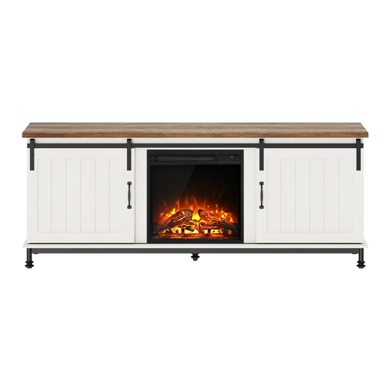
- Page 6 Two Assembly Options Option B (Fireplace TV Stand )
- Page 7 ● The provided glue(H) is to secure wood dowels(A) in place . When first inserting dowels, locate the appropriate hole for the dowel , place a small amount of glue in the hole and insert the dowel . Wipe away excess glue immediately.
- Page 8 · Insert dowels (A) into panels (4,5). · Attach panels (8,9) to panels (4,5) correctly. · Insert and secure cam locks (C) to panels (4,5) to lock it.
- Page 9 · Insert dowels (A) into panels (3,6). · Attach panels (7,10) to panels (3,6) correctly. · Insert and secure cam locks (C) to panels (3,6) to lock it.
- Page 10 · Attach part (13) to part (12) with Bolts (U).
- Page 11 2 Person Task Finished edge · Insert dowels (A) into panel (12). · Attach panel (12) to panels (7,10) correctly. · Insert and secure cam locks (C) to panel (12) to lock it.
- Page 12 2 Person Task · Insert dowels (A) into panels (3,4,5,6). · Attach panels (4,5) to panel (2) with screws (J). · Attach panels (3,6) to panel (2) with screws (J).
- Page 13 2 Person Task · DO NOT Tighten the bolts to ensure the assembly successfully in this step. · Attach parts (23) to part (20) with Bolts (G) correctly. · Attach parts (22) to parts (20,21) with Bolts (G). x 20 ·...
- Page 14 2 Person Task Step 1 Step 2 x 12 · Attach parts (20,21) to panel (2) with Bolts (G). · Then tighten all bolts to secure the unit in this assembly step.
- Page 15 · Attach parts (W) to panels (8,9,12) with Screws (V).
- Page 16 · Attach parts (P) to panels (16,17) with bolts (N). · Attach parts (S) to panels (16,17) with bolts (R).
- Page 17 2 Person Task · Slide panels (16,17) into designated area.
- Page 18 x 12 · Attach parts (Q) to back of panels (16,17) with screws (X) as shown.
- Page 19 · Carefully slide panels (18) into place along the back of the assembly.
- Page 20 · Screw cam bolts (B) into panel (1). x 12...
- Page 21 2 Person Task · Insert dowels (A) into panels (3,4,5,6,12). x 11 x 12 · Attach panel (1) to panels (3,4,5,6,12) correctly. · Insert and secure cam locks (C) to panels (3,4,5,6,12) to lock it.
- Page 22 · Secure parts (K) with Screws (L).
- Page 23 Option A (TV stand )
- Page 24 Option A (TV stand ) · Attach part (19) to panels (4,5) with screws (E) correctly, then part (19) x 10 to panels (1,2) with screws (E).
- Page 25 Option A (TV stand ) Finished edge Finished edge Finished edge x 12 · Insert the shelf supports (F) at the desired level and place the adjustable shelves (14,15) onto the shelf supports.
- Page 26 Option B (Fireplace TV Stand )
- Page 27 Option B (Fireplace TV Stand ) Finished edge Finished edge · Insert the shelf supports (F) at the desired level and place the adjustable shelves (14) onto the shelf supports.
- Page 28 Option B (Fireplace TV Stand ) · Insert fireplace (CC) from back of the tv stand.
- Page 29 Option B (Fireplace TV Stand ) · Attach parts (BB) to panel (25) with screws (X) correctly. · Attach part (25) to panels (4,5) with screws (X) correctly.
-
Page 30: Final Assembly
WARNING Serious or fatal injuries can occur from furniture tipping over. To prevent the furniture from tipping over we recommend that it is permanently fixed to the wall. Wall anchor and hardware Tools required: Phillips screwdriver, Power Drill, are included with this product. Please make sure hardware is 15/64”Drill Bit and Rubber Mallet. - Page 31 Final Assembly x 22 · Stick stickers (D) on cam locks (C). · Adjust leg (24) to level the unit.
Need help?
Do you have a question about the W04F3160W and is the answer not in the manual?
Questions and answers