
Subscribe to Our Youtube Channel
Related Manuals for Holman 4081P


Summary of Contents for Holman 4081P
- Page 1 Instruction Guide 4081P Holman Rancho Cordova, CA 95742 800-343-7486 InstallationSupport@Holman.com 20230713R4 DATE: ________________...
-
Page 2: Table Of Contents
Tools Needed ............................2 Before You Begin ..........................2 Parts ..............................3 Hardware (18-4081P) ........................... 4 Step 1 – Prepare Mount Brackets ......................5 Step 2 – Find Front Mount Locations ....................6 Step 3 – Install Mount Brackets ......................6 Step 4 –... -
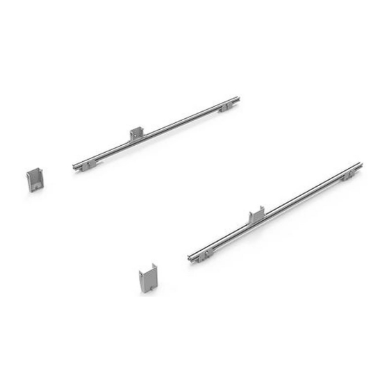
Page 3: Parts
Instructions – 4081P Parts For Technical Support Call: 800-343-7486, Monday-Friday, 7AM - 4 PM (PST) Page 3... -
Page 4: Hardware (18-4081P)
Instructions – 4081P Hardware (18-4081P) For Technical Support Call: 800-343-7486, Monday-Friday, 7AM - 4 PM (PST) Page 4... -
Page 5: Step 1 - Prepare Mount Brackets
Instructions – 4081P Hardware (18-4081P continued) Step 1 – Prepare Mount Brackets Attach threaded block inside extrusion foot bracket using #10 x 1/2" button head cap screws as shown. Repeat for all four extrusion foot brackets. Tighten. -
Page 6: Step 2 - Find Front Mount Locations
Instructions – 4081P Step 2 – Find Front Mount Locations Locate the forward two mounting locations on each side of van. This is where the mounting blocks will be mounted. Note: This picture shows on a 136” wheel base, high roof van. -
Page 7: Step 4 - Prepare Extrusion
Instructions – 4081P Step 4 – Prepare Extrusion Slide two 5/16” x 3/4" carriage bolts on opposite sides of the extrusion. Note: These are the shorter carriage bolts in the hardware kits. Repeat on each extrusion, for a total of eight carriage bolts on two extrusions. -
Page 8: Step 6 - Install Tall Feet
Instructions – 4081P Step 6 – Install Tall Feet Note: You may need to scrape away factory installed seam sealer underneath the “T” stud to allow clearance for the clamping bracket. Be careful not to scrape away all of the sealant. -
Page 9: Step 7 - Install Short Feet
Instructions – 4081P Step 7 – Install Short Feet Slide two 5/16” x 3/4" carriage bolts into the top slots of both mounted extrusions. Place the small feet over these carriage bolts. Secure feet to carriage bolts using 5/16” flat washers and 5/16” lock nuts. -
Page 10: Step 8 - Set Short Feet Location
Instructions – 4081P Step 8 – Set Short Feet Location If NOT using the optional ladder rack extender, set the center-to-center distance between rear and front feet to 71-1/2". 71-1/2” on center If using the optional ladder rack extender, set the center-to-center distance between rear and front feet to 96". -
Page 11: Step 9 - Mount Feet To Rack
Instructions – 4081P Step 9 – Mount Feet to Rack Center the rack crossbows over the feet, and bolt the bows to the feet using 3/8”-16 x 3/4” hex head, a 3/8” lock washer and a 3/8” flat washer in order shown.
Need help?
Do you have a question about the 4081P and is the answer not in the manual?
Questions and answers