Table of Contents
Advertisement
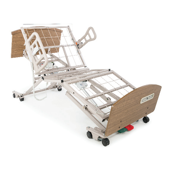
ZENITH 72 00 S E R I ES S HOWN
W I TH PE DAL LOCK A ND A DVA NCED
POS ITION IN G ( A PS ) F E AT U R ES
OPERATING MANUAL
SAVE THIS MANUAL FOR FUTURE USE.
FDA Recognized Standard:
ANSI/AAMI STD ES60601-1
Health Canada Recognized Standard:
CAN/CSA C22.2 No. 60601-1 (IEC 60601-1:20 12-Ed.3.1)
Includes International Standards:
IEC 60601-1, IEC 60601-2-52
EMC Standard:
IEC 60601-1-2 Ed. 4.1
BA_999-0953-190-INS-RevC23
Advertisement
Table of Contents
Troubleshooting

Related Manuals for Graham Field Basic American ZENITH 7200 Series


Summary of Contents for Graham Field Basic American ZENITH 7200 Series
- Page 1 ZENITH 72 00 S E R I ES S HOWN W I TH PE DAL LOCK A ND A DVA NCED POS ITION IN G ( A PS ) F E AT U R ES OPERATING MANUAL SAVE THIS MANUAL FOR FUTURE USE. FDA Recognized Standard: ANSI/AAMI STD ES60601-1 Health Canada Recognized Standard:...
-
Page 2: Table Of Contents
TABLE OF CONTENTS IMPORTANT SAFETY AND WARNING INFORMATION ........................... 3 IMPORTANT SAFETY AND WARNING INFORMATION ........................4 ELECTROMAGNETIC COMPATIBILITY (EMC) INFORMATION ...................... 4 ENTRAPMENT AND COMPLIANCE INFORMATION ........................5 RECOMMENDED MAINTENANCE ................................6 RECOMMENDED CLEANING AND DISINFECTION ..........................7 MECHANICAL AND ELECTRICAL INFORMATION ..........................8 OPERATING CONDITIONS ................................ -
Page 3: Important Safety And Warning Information
IMPORTANT SAFETY AND WARNING INFORMATION This product is a variable height, adjustable mattress platform. The expected service life of this product is fifteen years. Beds manufactured by Basic American Medical Products are designed for use within an institutional healthcare environment (i.e. assisted living, skilled nursing, transitional care, rehabilitation care, Environment (3), as defined in IEC60601-2-52 Safety Standard). -
Page 4: Electromagnetic Compatibility (Emc) Information
Risk of entanglement or injury may occur if the mattress used with mattress retainers does not fill the entire width between stops or which compresses to less than 1.50 inches under user’s weight. Mattress must be properly sized to fit the mattress support platform and must remain centered on the support platform relative to State and Federal guidelines. -
Page 5: Entrapment And Compliance Information
ENTRAPMENT AND COMPLIANCE INFORMATION On April 10, 2006, the FDA (U.S. Food and Drug Administration) released long-awaited guidelines for reducing the risk of bed entrapment: “Hospital Bed System Dimensional and Assessment Guidance to Reduce Entrapment”. The new Guidance identifies potential entrapment areas and those body parts most at risk for entrapment; provides design criteria for manufacturers of new hospital/convalescent beds;... -
Page 6: Recommended Maintenance
RECOMMENDED MAINTENANCE Regular maintenance of the Long Term Bed is necessary to ensure continuing proper and safe operation. Read and observe the following recommended maintenance schedule. An additional Maintenance Log page is available at the end of these instructions. RECOMMENDED MAINTENANCE INSPECTION PERIODS ITEM... -
Page 7: Recommended Cleaning And Disinfection
RECOMMENDED CLEANING AND DISINFECTION WARNING: Unplug the bed from the electrical outlet before servicing or cleaning. DO NOT steam clean or pressure wash any part of bed. DO NOT use corrosive or powdered cleansers to clean any part of bed. DO NOT immerse or soak any part of bed. -
Page 8: Mechanical And Electrical Information
MECHANICAL AND ELECTRICAL INFORMATION Zenith 7200 Series-Mechanical Note: All Dimensions are ± 0.25 inches Specification 7200 35" 7200 with Slide-Wide Overall Bed Length (with boards and wall saver) 80" Deck 87" 87" 84" Deck 91" 91" Sleep Deck Width 35" 35"... -
Page 9: Operating Conditions
The following warning labels have been placed on the bed to help protect you and the bed from damage. Do not remove any labels from the bed. WARNING! CAUTION WARNING: DO NOT LOWER BED WHEN OBJECTS ARE THIS BED IS SUITABLE FOR USE ONLY WITH Incompatible mattresses can create hazards. -
Page 10: Bed Setup And Operation Instructions
BED SETUP AND OPERATION INSTRUCTIONS NOTE: UNPACKING THE BED DISCARD END OF POWER CABLE 1. Large Block IS COILED FOR SHIPPING • Ensure all parts/components are included. 2. Notched 2 x 4 Board AND TIED, WITH CABLE 3. Honeycombed Block TIE, TO GRID WIRE WITH •... -
Page 11: Headboard And Footboard Assembly / Installation
HEADBOARD AND FOOTBOARD ASSEMBLY / INSTALLATION HEADBOARD INSTALLATION FOOTBOARD INSTALLATION 1. The headboard may come with four pre-installed 1. The footboard may come with four pre-installed inserts - if not already installed, assemble the four inserts - if not already installed, assemble the four inserts into the outside of the headboard as shown inserts into the outside of the footboard as shown above. -
Page 12: Slide-W-I-D-E Headboard And Footboard Positions Using The Quick-Release Detent Pins
SLIDE-W-I-D-E HEADBOARD AND FOOTBOARD POSITIONS USING THE QUICK-RELEASE DETENT PINS HEADBOARD INSTALLATION FOOTBOARD INSTALLATION 1. The headboard has four pre-installed inserts on the 1. The footboard has four pre-installed inserts on the inside surface. outside surface. 2. Position a right (#1) and left (#2) mounting bracket on 2. -
Page 13: Standard Mattress Retainer Installation
STANDARD MATTRESS RETAINER INSTALLATION (USING 2 MATTRESS RETAINERS) 1. Determine if you need to position your bed in an 84" or 4. On the head end, carefully squeeze the Mattress Retainer 80" configuration (84" outside holes; 80" inside holes - see ends inward, toward the center of the retainer, and insert Details A and B). -
Page 14: Mattress Retainer Installation For Optional Slide-W-I-D-E Deck
MATTRESS RETAINER INSTALLATION FOR OPTIONAL SLIDE-W-I-D-E DECK 1. The Slide-W-I-D-E Expandable/R+etractable Sleep Deck features two sets of Mattress Retainers that are positioned at bed head and foot corners. 2. To install, position the mattress retainers above the sleep deck corners with ends perpendicular to the sleep deck surface and long crooked bent ends on outside as shown below. -
Page 15: Standard Wireform Wallsaver Installation
STANDARD WIREFORM WALLSAVER INSTALLATION WALLSAVER ASSEMBLY 1. Position the Wireform Wallsaver with bent end facing upward and tab ends facing inward as shown at right. 2. Determine the position desired (see WALLSAVER POSITIONS below). 3. Gently squeeze the Wallsaver tab ends inward toward the center of the Wallsaver and, holding the tabs parallel with the caster base holes, slide the tabs into the holes while... -
Page 16: Plugging In The Footboard Staff Control
PLUGGING IN THE FOOTBOARD STAFF CONTROL STEP 1 - ATTACHING THE FOOTBOARD The Zenith series bed features a footboard Staff Control; however, the footboard is ordered separately with your bed because of the variety of board styles available. If ordered at the same time as the bed, the Staff Control Assembly and Shroud Cover will be pre-installed to the Footboard at the factory. - Page 17 ZENITH 7200 OPTIONAL ACCESSORIES Pivot Assist Bar Fixed Assist Bar ZA94700 ZA94900 Counter-Rotating Assist (Pair) 35” to 42" Width Extension Kit ZA91300 Bed Length Extension Kit 84" to 88" Length Extension Kit: ZA95772 ZA95600 (Extends 35", 42", and Slide-W-I-D-E Deck) www.grahamfi...
- Page 18 Left Intentionally Blank Left Intentionally Blank XXXXXXX XXXXXX Long (Trendelenburg) Wallsaver Side-Wallsaver Bumper (set of 2) ZA90070 ZA86200 (35") Plastic Pan Deck Kit Backup Battery & Battery Charger ZA87500 Backup Battery: ZA96100 Battery Charger: ZA96200 USB Phone Charger-Power Supply Kit Under-Bed-Light Kit (must be used with Staff Control and/or APS Hand Control Pendant) ZA96300...
- Page 19 Advanced Positioning Backlit Hand Control Pendant Standard Function Advanced Positioning with Trendelenburg / Reverse Trendelenburg Hand Control Pendant Hand Control Pendant with Standard Positioning with Chair Position Only ZA831306 999-0914-301SP 999-0914-305SP 1-Person Bed Transport Dolly (set) Board-Mounted IV Socket Kit ZA89900 unassembled ZA89900 assembled ZA19000...
-
Page 20: Operation Of Optional Slide-W-I-D-E 35" - 39" - 42" Expandable / Retractable Sleep Deck
OPERATION OF OPTIONAL SLIDE-W-I-D-E 35" - 39" - 42" EXPANDABLE / RETRACTABLE SLEEP DECK IMPORTANT SAFETY AND WARNING INFORMATION WARNING: Read and follow all instructions. Care must be taken when adjusting your Slide-W-I-D-E Expandable/Retractable Sleep Deck. To avoid possible injury, keep hands clear of deck ends when expanding or retracting, especially near the headboard or footboard. -
Page 21: Slide-W-I-D-E Sleep Deck Positioning
SLIDE-W-I-D-E SLEEP DECK POSITIONING 1. The Slide-W-I-D-E Expandable/Retractable Sleep Deck can be set to one of three widths: Fully Retracted = 35"; Partly Expanded = 39"; and Fully Expanded = 42". 2. To adjust the deck position, first remove all four quick-release detent pins from the underside of both Head and Foot Decks by pulling out the pins by the small rings. -
Page 22: Bed Operation
BED OPERATION ZENITH SERIES HAND CONTROL PENDANT OPERATION ZENITH SERIES WITH ZENITH SERIES WITH OPTIONAL ACCESSORY: STANDARD POSITIONING ADVANCED POSITIONING ZENITH SERIES WITH HAND CONTROL PENDANT HAND CONTROL PENDANT TRENDELENBURG / REVERSE TRENDELENBURG HAND CONTROL PENDANT BUTTON FUNCTION BUTTON FUNCTION HEAD DECK ANGLE UP SET TO CHAIR POSITION HEAD DECK ANGLE DOWN... -
Page 23: Bed Operation - Optional Staff Control Panel
BED OPERATION - OPTIONAL STAFF CONTROL PANEL * ALL LOCKED BUTTON HEAD DECK UP BUTTON HEAD DECK DOWN BUTTON KNEE & FOOT DECK UP BUTTON KNEE & FOOT DECK DOWN BUTTON CHAIR POSITION BUTTON UNDO CHAIR POSITION BUTTON KEY LOCK / UNLOCK BUTTON HI / LO (T / TR) LOCKED BUTTON HI / LO UP BUTTON HI / LO DOWN BUTTON... -
Page 24: Bed Operation - Chair Position
BED OPERATION - CHAIR POSITION www.grahamfi eld.com BA_999-0953-190-INS-RevC23... -
Page 25: Bed Operation - Trendelenburg / Reverse Trendelenburg Position
BED OPERATION - TRENDELENBURG / REVERSE TRENDELENBURG POSITION 1. Ensure the Staff Control HI/LO function is not locked out (orange lock icon). To unlock, simultaneously press Key 1 and HI/LO Locked button 2. 2. To move the bed to Trendelenburg position (foot end up), press button 3. - Page 26 ZENITH 7200 ELECTRICAL CABLING www.grahamfi eld.com BA_999-0953-190-INS-RevC23...
- Page 27 ZENITH 7200 ELECTRICAL CABLING www.grahamfi eld.com BA_999-0953-190-INS-RevC23...
-
Page 28: Troubleshooting
TROUBLESHOOTING NOTHING WORKS — NO POWER 1. Verify the outlet is supplying power. 6. Replace the Hand Control Pendant with a known good operating Pendant. If the bed 2. Ensure the power cord is not pinched, works, replace the Hand Control Pendant. frayed, or damaged in any way. -
Page 29: Knee Doesn't Lower, Audible Solid Beep Warning
KNEE DOESN’T LOWER, AUDIBLE SOLID BEEP WARNING NOTE: As a result of the bed’s programmed If the solid beep is present when trying to capability to achieve APS positioning, lower the knee: the Knee Motor will not lower if the 1. -
Page 30: General Troubleshooting Quick Reference
GENERAL TROUBLESHOOTING QUICK REFERENCE NOTE: Advanced Service Troubleshooting Procedures, Flow Charts and Service Components can be found at www.grahamfield.com. Motor Cables Motor cables are interchangeable. Test a motor cable by attaching it to a known good motor and known good Control Box port and operating it. -
Page 31: Limited Warranty
LIMITED WARRANTY SCOPE OF WARRANTY GF Health Products, Inc. (“GF”) warrants to the Original Purchaser only that it will replace or repair components, at GF’s sole discretion, that are defective in material or workmanship under normal use and service. All warranties are conditioned upon the proper use of the products strictly in accordance with good commercial practice and applicable GF instructions and manuals, including proper use and maintenance. - Page 32 Manufactured By: GF Health Products, Inc. One Graham-Field Way, Atlanta, GA 30340 Made in USA +1 770.368.4700 © 2023, GF Health Products, Inc. All Rights Reserved. Information contained herein is subject to change without notice. Basic American Medical Products is a trademark The most current and complete product information can be found on our website.
Need help?
Do you have a question about the Basic American ZENITH 7200 Series and is the answer not in the manual?
Questions and answers