
Related Manuals for Graham Field Hausted EPC500ST


Summary of Contents for Graham Field Hausted EPC500ST
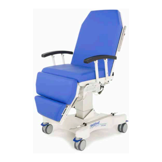
- Page 1 EPC500ST PROCEDURE CHAIR OPERATING MANUAL READ THIS MANUAL BEFORE OPERATING YOUR EPC500ST PROCEDURE CHAIR. SAVE THIS MANUAL FOR FUTURE USE. EPC500ST-INS-LAB-REVA21...
-
Page 2: Table Of Contents
CONTENTS INTRODUCTION — A WORD FROM GF HEALTH PRODUCTS, INC....................4 INDICATIONS FOR USE ................................. 4 SERVICE INFORMATION ................................ 4 ADVISORY ....................................4 LIST OF WARNINGS AND CAUTIONS ............................5 SIGNIFICANCE OF SAFETY STATEMENTS ..........................5 DANGER / WARNING / CAUTION / NOTICE SUMMARY ...................... 5 WARNING: TO REDUCE THE RISK OF BURNS, FIRE, ELECTRIC SHOCK, OR PERSONAL INJURY .... - Page 3 9.6 SIGNAL INPUT / OUTPUT PARTS PORT 1 .......................... 41 9.7 RECOMMENDED SEPARATION DISTANCES BETWEEN PORTABLE AND MOBILE RF COMMUNICATIONS EQUIPMENT AND HAUSTED EPC500ST PROCEDURE CHAIR 1 ..................42 9.8 NOTES TO SECTIONS 9.2 - 9.7............................42 9.9 CERTIFICATIONS.................................. 42 INDEX ......................................
-
Page 4: Introduction - A Word From Gf Health Products, Inc
Indications for Use The Hausted EPC500ST Procedure Chair is intended for use in patient treatment, transport or recovery. It has a radiolucent back for X-ray imaging capabilities of 20" x 25 " (50.8 cm x 64.8 cm) width x height with a range of 0°... -
Page 5: List Of Warnings And Cautions
LIST OF WARNINGS AND CAUTIONS IMPORTANT: Before using the Hausted EPC500ST Procedure Chair, please read and adhere to the following safety precautions and warnings. Failure to do so could result in serious personal injury or damage to the EPC500ST Procedure Chair. -
Page 6: Warning - Cautions And Proper Operation
WARNING — CAUTIONS AND PROPER OPERATION WARNING: The EPC500ST Procedure Chair has a maximum patient weight capacity 600 lb (272 kg), EVENLY DISTRIBUTED. WARNING: The EPC500ST Procedure Chair has a maximum weight, including equipment weight and maximum patient weight, of 865 lb (393 kg). WARNING: The chair is not intended to replace a stretcher or gurney. -
Page 7: Electromagnetic Compatibility (Emc) Information
WARNING: This product can expose you to chemicals including Di(2-ethylhexyl)phthalate (DEHP) which is known to the State of California to cause cancer or birth defects or other reproductive harm. For more information go to www.P65Warnings.ca.gov/furniture. CAUTION: Stow away power cord when not in use to prevent injury or damage. ELECTROMAGNETIC COMPATIBILITY (EMC) INFORMATION WARNING: Medical Electrical Equipment needs special precautions regarding EMC and... -
Page 8: Uncrating Instructions
UNCRATING INSTRUCTIONS IMPORTANT — REPORT ANY SHIPPING DAMAGE IMMEDIATELY WARNING: Inform shipper of any damages — leave carton intact. Leave equipment in the receiving area until inspection is complete. NOTICE — POSSIBLE EQUIPMENT DAMAGE s NOTICE: The crate contains fragile, expensive medical equipment. Uncrate and handle carefully. If after uncrating the equipment you find any damage (no matter how slight), report the damage to GF Health Products, Inc. -
Page 9: Operating Instructions
OPERATING INSTRUCTIONS EPC500ST SPECIFICATIONS Info: All dimensions are specified in [millimeters] and inches. Unless otherwise noted, all dimensions are ± [10 mm] .375 in. Dual dimensions are minimum (left) and maximum (right) when shown in chair position, and opposite — maximum (left) and minimum (right) when shown in Trendelenburg position. -
Page 10: Electrical Specifications
1994 / 1791 78.5 / 70.5 673 / 470 26.5 / 18.5 6° 34.5 15.5 35.0 Reverse Trendelenburg position, side view Electrical Specifications Product Classification Input Voltage 100-240V~ 50/60 Hz Amperage Maximum 4.5A Duty Cycle 5% 1 min. in 19 min. on Battery 10% 2 min. -
Page 11: Features, Warnings And Proper Operation Operating Instructions
FEATURES, WARNINGS AND PROPER OPERATION OPERATING INSTRUCTIONS WARNINGS — CAUTIONS AND PROPER OPERATION (See Diagram on following page) WARNING: The EPC500ST Procedure Chair has a maximum patient weight capacity of 272 kg (600 lb), EVENLY DISTRIBUTED. WARNING: The EPC500ST Procedure Chair has a maximum weight capacity, including equipment weight and patient weight, of 393 kg (865 lb). -
Page 12: Features (Shown In Illustration)
Features (Shown in Illustration) TOP TUBE WARNING LABEL See WARNINGS C & H BACK OF CHAIR WARNING LABEL PATIENT COMFORT CUSHIONS See WARNINGS A & P PATIENT ENTRY See WARNINGS G & H PIVOTING RAIL See WARNING F SAFETY STRAP See WARNING F RAIL LATCH See WARNINGS F &... -
Page 13: Braking And Steering Operation With Smart Caster Technology
BRAKING AND STEERING OPERATION WITH SMART CASTER TECHNOLOGY 3.3.1 Applying the Brakes To apply the four wheel central braking system with the pendant, press the pendant Brake On / Off button; the LED above the button then illuminates green (Figure 3.3-1), and the blue caster pedals on all four corners of the chair automatically lower to lock Figure 3.3-1... -
Page 14: Activating Advanced Steer Mode - Pendant
3.3.3 Activating Advanced Steer Mode — Pendant To activate Advanced Steer Mode with the pendant, press the pendant Steer Mode On / Off button. The LED above the button then illuminates green (Figure 3.3-5), and the blue caster pedals automatically rise (Figure 3.3-6) at the patient foot end of the chair. -
Page 15: Deactivating Advanced Steer Mode - Pendant
3.3.5 Deactivating Advanced Steer Mode — Pendant To deactivate Advanced Steer Mode with the pendant, press the pendant Steer Mode On / Off button. The LED above the button will go out (Figure 3.3-7) and the blue caster pedals in Steer-Lock position will automatically lower to neutral position (Figure 3.3-4). -
Page 16: Electric Control Locations
ELECTRIC CONTROL LOCATIONS 3.4.1 Pendant Control Storage Location The pendant is located on the pendant holder on either side of the chair (Figure 3.4-1). s NOTICE: Place pendant on holder when not in use. Keep cord clear of moving parts. 3.4.2 Plug Location Figure 3.4-1... -
Page 17: Height And Patient Surface Adjustment
HEIGHT AND PATIENT SURFACE ADJUSTMENT Figure 3.5-1 3.5.1 LOCK / UNLOCK (button 1) LOCK Press and hold LOCK button (1) for three seconds to lock all functions. After five LED flashes, all four UP LED’s (2-5) illuminate steady green, indicating they are now locked; an audible signal also indicates when locked and beeps up to three times until button is released. -
Page 18: Back Section Up / Down (Buttons 3 And 10)
HEIGHT AND PATIENT SURFACE ADJUSTMENT Figure 3.5-2 3.5.3 BACK SECTION UP / DOWN (buttons 3 and 10) BACK UP Press and hold BACK UP button (3) until desired position is achieved. LED illuminates steady green while pressed, goes out when released. Press and hold BACK DOWN button (10) until desired position is BACK DOWN achieved. -
Page 19: Leg Up / Down (Buttons 5 And 12)
HEIGHT AND PATIENT SURFACE ADJUSTMENT Figure 3.5-3 3.5.5 LEG UP / DOWN (buttons 5 and 12) Press and hold LEG UP button (5) until desired position is achieved. LED illuminates steady green while pressed, goes out LEG UP when released. Press and hold LEG DOWN button (12) until desired position is achieved. -
Page 20: Trendelenburg, Supine And Reverse Trendelenburg Positions (Buttons 7, 14 And 20)
HEIGHT AND PATIENT SURFACE ADJUSTMENT Figure 3.5-4A 3.5.7 TRENDELENBURG, SUPINE and REVERSE TRENDELENBURG Positions (buttons 7, 14 and 20) Press and hold TRENDELENBURG button (7) until desired position is achieved. Chair automatically lowers back TRENDELENBURG section, raises leg section, and tilts seat section backward simultaneously;... -
Page 21: Memory And Preset Functions (Buttons 15-18)
3.5.8 Memory and Preset Functions (Buttons 15-18) Figure 3.5-4B MEMORY Position chair to desired position. Enter MEMORY MODE by pressing and holding MEMORY button (15) for three seconds until LED flashes. Once MEMORY LED flashes, simultaneously press and hold MEMORY button (15) and desired PRESET button (16, 17, or 18) until beeping stops (MEMORY LED will stop flashing and go out and PRESET LED will illuminate). Once MEMORY button and PRESET button are released, the position saves, LEDs go out, and MEMORY MODE exits. (After entering MEMORY MODE, PRESET buttons that illuminate are already programmed, but can be overwritten; PRESET buttons that don’t illuminate are not yet programmed.) PRESET 1 Press and hold PRESET 1 button until saved pre-programmed position is achieved. -
Page 22: Battery (Button 19)
HEIGHT AND PATIENT SURFACE ADJUSTMENT Figure 3.5-5 3.5.9 BATTERY (button 19) LED illuminates steady green when battery discharges to 20% capacity or less. BATTERY Press and hold LOCK and BATTERY buttons (1 and 19) for one second to unlock all functions. A quick LED flash indicates they are now unlocked; an audible signal also indicates when unlocked. -
Page 23: Adjustable Footrest
ADJUSTABLE FOOTREST 3.6.1 Repositioning the Footrest The footrest has three positions: retracted, lower, and upper. With the pan in the retracted position, pull out anywhere on top of the pan (Figure 3.6-1). The footrest will drop into the lower position (Figure 3.6-2). Figure 3.6-1 To move the footrest into the upper position, grasp both sides of the pan and tilt the pan up... -
Page 24: Adjustable Leg Extension
ADJUSTABLE LEG EXTENSION 3.7.1 Repositioning the Motorized Leg Extension The motorized leg extension can be adjusted to make the footrest up to 8.0" (20 cm) longer when fully extended (Figure 3.7-1). Extending the Motorized Leg Extension Figure 3.7-1 Info: The motorized leg extension can only be extended when the leg is in the horizontal position. -
Page 25: Operation While Leg Extension Is Retracted
Operation While Leg Extension Is Retracted seat 55° A. When the leg extension is fully retracted and the chair height is below 22" (55.9 cm) (top of seat to floor), the leg section can only be positioned between 0° and 55° from horizontal. -
Page 26: Pivoting Rails
PIVOTING RAILS 3.8.1 Repositioning the Rail The chair rail has two positions, raised and lowered. Both positions lock the rail into place. Lowering the Pivoting Rail Figure 3.8-1 Grasp the top of the rail, push or pull outward on the black release plunger (Figure 3.8-1), and pull the top of the rail toward the head end of the chair (Figure 3.8-4);... -
Page 27: Push Handles
PUSH HANDLES 3.9.1 Operating the Push Handles Push Handles are stowed away when not in use (Figure 3.9-1). Push Handles may be operated with the back in either raised or lowered position. Rotating and Positioning the Hand Grips Figure 3.9-1 The Hand Grips rotate 360°... -
Page 28: Common Optional Accessories
3.10 COMMON OPTIONAL ACCESSORIES 3.10.1 Installing the IV Rod Remove the IV Rod from the clips located on the base (Figure 3.10-1). Insert IV Rod into Figure 3.10-1 preferred IV well — there are two sockets on both sides of chair (Figure 3.10-2). Return IV Rod to storage clips when not in use (Figure 3.10-1). -
Page 29: Troubleshooting Guide
TROUBLESHOOTING GUIDE DANGER: SHOCK HAZARD — To reduce the risk of electric shock, unit is to be serviced by qualified service personnel only. DANGER: SHOCK HAZARD — Always disconnect the power source whenever troubleshooting or servicing any electric powered chair. The following list of problems and their solutions will assist you in determining what may be causing your chair not to function as designed. - Page 30 Then HOME button beeps Leg extension not fully retracted. Press RETRACT button until leg extension reaches when pressed; nothing the fully retracted position. moves. GF Health Products, Inc. may be contacted at 1.770.368.4700, or your authorized distributor if outside the U.S., for additional information required to service or repair the equipment. EPC500ST-INS-LAB-RevA21...
-
Page 31: Control Box
CONTROL BOX Battery Life LED Amber SEAT TILT Insert screwdriver tip here to release Control Box cover BATTERY HEIGHT BACK Control Box LED Amber / Green Control Box Features BATTERY REPLACEMENT DANGER: SHOCK HAZARD — To reduce the risk of electric shock, unit is to be serviced by qualified service personnel only. - Page 32 4. Release the battery by pressing the tab on the battery mounting bracket toward the front of the chair (Figure 4.2-4) and then slide the battery to the left so battery tabs align with bracket cutouts. The battery can be pulled up and removed once properly aligned (Figure 4.2-5).
-
Page 33: Preventive Maintenance For The User
PREVENTIVE MAINTENANCE FOR THE USER Component Cleaning Procedure Schedule Cleaning Agent * Special Notes Pads / Mattresses Wipe with damp cloth to Routine hospital grade Use only medium remove any foreign material disinfectants, soap and strength cleaners water Do not steam clean After or pressure wash each... -
Page 34: Optional Accessories
OPTIONAL ACCESSORIES WARNING: Use only accessories approved by GF Health Products, Inc. with this device. The use of accessories, transducers, and cables other than those specified by the manufacturer may result in increased emissions or decreased immunity of Hausted equipment. Info: To order accessories, or for more detailed information on accessories, please contact GF Health Products, Inc. -
Page 35: Gf Health Products, Inc. Limited Warranty For Hausted Brand Stretchers And Chairs
GF HEALTH PRODUCTS, INC. LIMITED WARRANTY FOR HAUSTED BRAND STRETCHERS AND CHAIRS SCOPE OF WARRANTY GF Health Products, Inc. (“GF”) warrants to the original purchaser only that it will replace or repair components, at GF’s sole discretion, that are defective in material or workmanship under normal use and service. All warranties are conditioned upon the proper use and maintenance of the products strictly in accordance with good commercial practice and applicable GF instructions and manuals . -
Page 36: Disposal And Key To Symbols
DISPOSAL AND KEY TO SYMBOLS DISPOSAL Hausted equipment and accessories can be disposed of. We recommend disassembling and dividing the equipment and components into different waste groups such as: metal, cable, electronic, recoverable resource and plastic for recycling or combustion. Most plastic components are provided with a plastic types code and fiber content to aid sorting of plastic parts. -
Page 37: Appendix
APPENDIX GUIDANCE AND MANUFACTURER’S DECLARATION — ELECTROMAGNETIC EMISSIONS The Hausted EPC500ST Procedure Chair is intended for use in the electromagnetic environment specified below. The customer or the user of the Hausted EPC500ST Procedure Chair should assure that it is used in such an environment. Emissions Test Compliance Electromagnetic Environment — Guidance RF emissions Group 1 The Hausted EPC500ST Procedure Chair uses RF CISPR 11 energy only for its internal function. -
Page 38: Enclosure Port Immunity To Rf Wireless Communications Equipment 1
ENCLOSURE PORT IMMUNITY TO RF WIRELESS COMMUNICATIONS EQUIPMENT Test Maximum MMUNITY Band Service Modulation Distance frequency power TEST LEVEL (MHz) (MHz) (V/m) Pulse modulation 380 –390 TETRA 400 18 Hz GMRS 460, ± 5 kHz deviation 430 – 470 FRS 460 1 kHz sine Pulse LTE Band 13,... -
Page 39: Input Ac Power Port 1
INPUT AC POWER PORT MMUNITY TEST LEVELS Basic EMC Phenomenon standard Professional healthcare facility environment Electrical fast transients / IEC 61000-4-4 ± 2 kV a) l) o) bursts 100 kHz repetition frequency a) b) j) o) IEC 61000-4-5 ± 0,5 kV, ± 1 kV Surges Line-to-line a) b) j) k) o) -
Page 40: Patient Coupling Port 1
CONTINUED that do not have a surge protection device in the primary power circuit may E EQUIPMENT ME SYSTEMS be tested only at ± 2 kV line(s) to earth and ± 1 kV line(s) to line(s). Not applicable to C LASS II ME EQUIPMENT ME SYSTEMS Direct coupling shall be used. -
Page 41: Signal Input / Output Parts Port 1
SIGNAL INPUT / OUTPUT PARTS PORT MMUNITY TEST LEVELS Basic EMC Phenomenon standard Professional healthcare facility environment IEC 61000-4-2 ± 8 kV contact LECTROSTATIC DISCHARGE ± 2 kV, ± 4 kV, ± 8 kV, ± 15 kV air Electrical fast IEC 61000-4-4 ±... -
Page 42: Recommended Separation Distances Between Portable And Mobile Rf Communications
The Hausted EPC500ST Procedure Chair is intended for use in an electromagnetic environment in which radiated RF disturbances are controlled. The customer or the user of the Hausted EPC500ST Procedure Chair can help prevent electromagnetic interference by maintaining a minimum distance between portable and mobile RF communications equipment (transmitters) and the Hausted EPC500ST Procedure Chair as recommended below, according to the maximum output power of the communications equipment. -
Page 43: 10 Index
10 INDEX Accessories, optional, list 34 Pivoting rail, lowering 26 Advanced steer mode, deactivate 15 Pivoting rail, raising 26 Advisory 4 Preventive maintenance for the user 33 A word from GF Health Products, Inc. 4 Push handles 27 Push handles, operating 27 Back, emergency drop 22 BACK SECTION UP/DOWN buttons 18 Quick drop activation 22...
Need help?
Do you have a question about the Hausted EPC500ST and is the answer not in the manual?
Questions and answers