
Subscribe to Our Youtube Channel
Related Manuals for LEMKEN Thulit MF/600


Summary of Contents for LEMKEN Thulit MF/600
- Page 1 OPERATING INSTRUCTIONS HOEING HARROW THULIT MF Thulit MF/600 Thulit MF/900 Thulit MF/1200 en-GB | Item no. 17517508 | BA Rev _/2023-12...
- Page 2 Pass these instructions to all users / owners. Original instructions © 2023 | This documentation is copyright protected. The copyright remains with LEMKEN GmbH & Co. KG, Weseler Straße 5, D-46519 Alpen. The texts, diagrams and drawings must not be duplicated, distributed or disclosed in any other way,...
-
Page 3: Table Of Contents
Table of contents Table of contents About these instructions............................1 1.1 Introduction................................. 1 1.2 Target groups..............................3 1.3 Applied presentations............................. 3 1.3.1 Signal words and hazard statements...................... 3 1.3.2 Symbols and text markings........................4 1.3.3 Direction specifications..........................4 1.4 Further applicable documents........................5 Safety.................................... - Page 4 Table of contents Operation................................... 46 6.1 Basic operation..............................46 6.1.1 Folding machine............................46 6.2 Working with the machine.......................... 46 6.2.1 Typical work procedure..........................46 Cleaning and care..............................48 7.1 After working in the field..........................48 7.2 Cleaning with high-pressure cleaner....................... 48 Decommissioning..............................
- Page 5 Appendix..................................71 A Type plate variants............................72 B Tightening torques screws ..........................73 C LEMKEN overview of operating materials....................77 D Calculation of axle load and ballasting for mounted machines............79 E Cross shaft overview............................83 en-GB | Item no. 17517508 | BA Rev _/2023-12...
- Page 6 Table of contents en-GB | Item no. 17517508 | BA Rev _/2023-12...
-
Page 7: About These Instructions
About these instructions About these instructions Introduction These operating instructions are important and belong to the machine's scope of delivery. These operating instructions must be available to the user at the place of use. Always read chapter "Safety" before using the machine for the first time. - Page 8 About these instructions Validity range These operating instructions describe operation of the machine after initial commissioning by the LEMKEN sales partner and handover to the operator. Prior to operation, initial commissioning and instruction in operation, setting/adjustment and maintenance must have been carried out.
-
Page 9: Target Groups
About these instructions Target groups The target groups of these operating instructions are operators, users and service personnel of the machine. The target groups must meet the requirements for operators, users and service personnel as defined in these instructions. INFORMATION Ä... -
Page 10: Symbols And Text Markings
About these instructions 1.3.2 Symbols and text markings Symbol, text Meaning marking In front of and in texts Marking for routine maintenance tasks ● Activities that demand the help of service staff. Listing Position numbers [1], Example: ‘Settings’ Software element Example: [OK] Softkey, key, switch and button [kg]... -
Page 11: Further Applicable Documents
Operating instructions for the combination machine Latest versions of the LEMKEN docu‐ ments The latest versions of the LEMKEN documents can be found in the LEMKEN Online Information System (LEONIS). Users can access LEONIS via the QR code or the LEMKEN website. -
Page 12: Safety
Safety Safety Machine limits Intended use The machine is used for soil cultivation on agricultural land. It may only be used in accordance with the recognised rules of good agricultural practice. The permitted working depth is limited to the cultivatable soil horizons. Use on heavily or deeply frozen soils, in soil horizons with unweathered parent rock and soil horizons with loose rock or solid bedrock is not regarded to be in compliance with the designated purpose. -
Page 13: Requirements Of Operators, Users And Service Personnel
Safety Hazardous area The machine and the area in the immediate vicinity of the machine is deemed a hazardous area. This includes the space over the entire width, length and height of the machine, as well as an additional safety distance of two metres to the machine. -
Page 14: General Safety Information
Safety Qualified specialists For the purposes of these instructions, qualified specialists are all per‐ sons who, on the basis of their professional training and experience, carry out the tasks assigned to them in a professional manner. Qualified specialists have knowledge of the relevant standards and regulations, recognise possible hazards and avoid hazards independently. - Page 15 Safety Safety equipment Existing and fully functional safety devices protect against death or serious personal injury. Keep the labels legible and renew them, if necessary. ► Replace damaged safety devices. ► Install dismantled safety devices before commissioning. ► Move the safety devices to the protective position. ►...
-
Page 16: Safety Information On Hazardous Areas Of The Machine
Safety Hydraulic assembly The hydraulic assembly might be under high pressure. Hydraulic oil leaking under pressure can penetrate through the skin into the body. Injury to body parts, face, eyes and unprotected skin may result. The hydraulic assembly might be hot. The hydraulic oil is harmful to health. - Page 17 Safety Area between the tractor and When standing between the tractor and machine, there is a risk due to machine tractor movements or sudden machine movements. Secure the tractor against rolling away. ► Before operating the linkage: Keep all persons away from the ►...
- Page 18 Safety Moving hazardous area The hazardous area of the machine during operation. Moving hazardous area The hazardous area includes the area in driving direction across the entire width of the machine. There must be NO persons in the hazardous area. If there are persons in the hazardous area, may result in death or injury to persons.
- Page 19 Safety Folding range Hazardous areas when folding the implement There should be NO persons present in the folding range. If persons are present in the folding range, it may result in death or serious injury. Lateral sections may, due to their height touch overhead lines during the folding processes and cause flashovers.
-
Page 20: Safety Information On Structural Modifications
Safety Safety information on structural modifications Structural modifications Structural modifications and extensions can impair the functionality and operational safety of the machine. This may result in death or injuries. Auxiliary equipment and spare parts must comply with the manufactur‐ er's requirements. Modifications and conversions may only be carried out with the ►... - Page 21 Safety Behaviour during flashover of over‐ Flashovers cause high electrical voltages on the outside of the tractor- head lines machine combination. Large voltage differences occur on the ground around the tractor-machine combination. Large steps, lying down or supporting yourself on the ground may cause life-threatening electrical currents (step voltage).
- Page 22 Safety Road travel The user operates the machine via control elements such as tractor control units, touch screen, buttons or joystick. Touching the control elements may trigger functions and machine movements, even if touching the control elements was not intended. Disabling machine functions before driving on the road.
-
Page 23: Design And Description
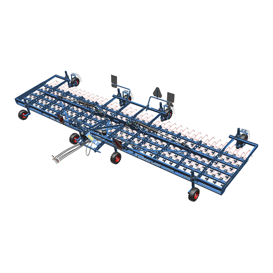
Design and description Design and description Machine overview INFORMATION The machines can be equipped differently at the factory. – Standard components, special equipment or optional accessories are not marked separately. – Contents in this document may differ from the actual equipment of the machine. -
Page 24: Machine Safety
Design and description Type plate The machine is marked with a type plate. The machine type can be identified uniquely by the type plate. Further information about the type plate: Ä Appendix A ‘Type plate variants’ on page 72 Machine safety 3.2.1 Position of the label Thulit MF - Overview of safety symbols, warning stickers and other symbols... - Page 25 Design and description Reading the operating instructions Incorrect use or operation of the machine can result in death or serious injury. Before commissioning: Read and observe the operating instructions. ► Follow the instructions for action. ► Turn off the engine A tractor with the engine running can cause unintentional movements.
- Page 26 Design and description Sling points Sling points for lifting processes Jack positioning points Positioning points for jack Lifting points for fork-lift truck Lifting points for fork-lift truck en-GB | Item no. 17517508 | BA Rev _/2023-12...
-
Page 27: Safety Devices
Design and description Hydraulic equipment Control units Coupling Line Consumer Single Double Free acting acting return +/– Folding * ● Blue +/– Folding ** ● Orange P = Pump line Harrow adjustment ● ● T = Tank line LS = Control cable (Load-Sensing) * Depending on the equipment of the machine: Folding left and right or optionally only right ** Depending on the equipment of the machine: Folding left optional... - Page 28 Design and description Front marking Front white reflectors Lateral reflectors Warning board Front marking Warning boards Lateral reflectors White reflectors Rear lighting equipment Example of rear lighting equipment Warning board Lateral reflectors LED lighting equipment Round reflectors en-GB | Item no. 17517508 | BA Rev _/2023-12...
-
Page 29: Headstock
Design and description Rear lighting equipment Example of rear lighting equipment Warning boards Lateral reflectors LED lighting equipment Red reflectors 3.2.3.2 Hydraulic transport locking device In transport position, the hydraulic-mechanical transport locking device prevents the lateral parts from folding out unintentionally. Headstock The headstock has been designed according to standard ISO 730. -
Page 30: Commissioning
Commissioning Commissioning Preparing an attachment 4.1.1 Checking suitability of the tractor WARNING Risk of accident due to unsuitable tractor If the tractor is not suitable for the machine, compo‐ nents of the machine may be overloaded and the tractor- machine combination may not be steered safely. This may result in accidents with injuries or death of persons or damage to the machine. -
Page 31: Attaching The Machine
Commissioning Assembly group Requirement Check Hydraulic oil The hydraulic oils of the machine and the tractor are compatible. Ä Chapter 12.7 ‘Operating materials’ on page 66 Axle loads Ä Appendix D ‘Calculation The axle loads and the required ballasting have been determined and of axle load and ballasting taken into account. -
Page 32: Changing The Mounting Position
Commissioning 4.2.1 Changing the mounting position Mounting positions depending on the equipment of the machine Top link pin position Upper hole (slot) Lower hole Pin position for the lateral section movement en-GB | Item no. 17517508 | BA Rev _/2023-12... - Page 33 Commissioning Pin in slot: Use with support wheel Pin in fixed hole: Use without support wheel Equipment of the Pin position for the lateral section move‐ Top link pin position * machine ment ** Slot Fixed hole Slot Fixed hole 2x front support ●...
-
Page 34: Attaching A Machine With Headstock
Commissioning 4.2.2 Attaching a machine with headstock Top link pin Cross shaft Top link Headstock Lower link INFORMATION Observe the tractor documents. Ä Chapter 1.4 ‘Further applicable documents’ on page 5 1. Switch the rear lifting gear of the tractor to position control. 2. - Page 35 Commissioning 8. Adjust the length of the top link parallel to the lower links 9. Connect the top link to the top link pin 10. Secure top link pin with the linch pin. ð Machine with headstock has been mounted. Connect lines and hoses 1.
-
Page 36: Checking And Adjusting The Machine
Commissioning Attaching the rotary knob for the harrow tine pressure Preconditions: √ The machine has been mounted to the tractor. √ The operation terminal is connected to the hydraulic assembly. ► Attach the operation terminal in the tractor cab magnetically in the driver's operating area. - Page 37 Commissioning On switch Off switch The following adjustment options are possible at the operation ter‐ Rotary knob minal: Switching the hydraulic harrow tine pressure on and off – Switch on = harrow tines move to the operating position. – Switch off = harrow tines move to the transport position, e.g. for driving on public roads.
-
Page 38: Position Of The Support Wheels
Commissioning 4.3.2 Position of the support wheels Overview Underframe clearance The following adjustment options are possible at the support wheels: Track Underframe clearance of the machine for adjusting the pitch Weed harrow angle of the tines Track of the support wheel (horizontal) for adapting to the crop and the specified tracks Adjustment of the tine pressure for the weed harrow on the support wheel... - Page 39 Commissioning Changes to the support wheel position influence the underframe clear‐ Adjusting the pitch angle of the ance and, therefore, the pitch angle of the tines: harrow tines via the support wheels Lower underframe clearance = drag position Higher underframe clearance = grade position Preconditions: √...
- Page 40 Commissioning Adjusting the track To protect the crop and to adapt the machine to the local conditions, the tracks of all support wheels can be adjusted. Preconditions: √ The machine has been lifted and secured against unintentional lowering. √ The support wheels are relieved. √...
- Page 41 Commissioning 3. Adjust the track, e.g. adapt it to the track of the tractor. ð The pin can be inserted in the hole on the right or on the left. In the target position, a hole for the pin is flush with a groove on the guide rail.
- Page 42 Commissioning Adjusting the weed harrows on the support wheel Preconditions: √ The machine has been lifted and secured against unintentional lowering. √ The support wheels are relieved. √ The tractor engine has been switched off. √ Tractor-machine combination is secured against rolling away. 1.
-
Page 43: Adjusting The Contour Adjustment
Commissioning 3. Install the pins on both sides of the support wheel and secure them with spring pins. 4. Adjust all the other weed harrows at the support wheels to the same height. ð The weed harrows at the support wheels have been adjusted. - Page 44 Commissioning √ The tractor engine has been switched off. √ Tractor-machine combination is secured against rolling away. 1. Remove the pin. 2. Remove the safety screw. 3. Pull the support wheel with the square tube from the holder. 4. Remove all the other outer support wheels in the same manner. ð...
- Page 45 Commissioning 3. Install the pin. 4. Secure the pin with the linch pin. 5. Mount all the other outer support wheels in the same manner. ð The outer support wheels are mounted. Adjusting movement of the lateral INFORMATION sections If outer support wheels are mounted or removed, move‐ ment of the lateral sections must be adjusted prior to operation.
- Page 46 Commissioning √ The tractor engine has been switched off. √ Tractor-machine combination is secured against rolling away. 1. Relieve the lateral section. 2. Remove the pin 3. Install the pin in the following position: (slot) for a moving lateral section for use of outer support wheels for a rigid lateral section without outer support wheels 4.
-
Page 47: Road Travel
Road travel Road travel Information on road travel INFORMATION Laws on driving on public roads differ in many countries. Operators and users are responsible for adherence to applicable laws. Observe the following legal requirements: Dimensions Weights Braking system Lighting equipment Markings NEVER exceed the maximum transport speed of the machine. - Page 48 Road travel Assembly group Requirement Check chains and stabilisers To ensure the machine is positioned centrally behind the tractor, the lower links are secured in place (no lateral move‐ ment). The instructions of the tractor manufacturer are observed. Lighting equipment Lighting equipment is mounted and fully functional.
- Page 49 Road travel 2. Move the support wheel with the square tube to the top position. ð Support wheel is in the transport position. 3. Install the pin and secure it with the linch pin. 4. Adjust all the other support wheels to the same height. ð...
-
Page 50: Preparing The Lighting Equipment For Road Travel
Road travel Moving the harrow tines to the trans‐ port position On switch Off switch ► Switch off the hydraulic harrow tine pressure at the switch Rotary knob ð Move the harrow tines to the transport position. Preparing the lighting equipment for road travel Before driving on the road: 1. - Page 51 Road travel Testing the lighting equipment 1. Actuate the direction indicator in the tractor. 2. The tell-tale light for the direction indicator on the tractor the tell-tale light for the direction indicator on the machine flash. ð The lighting equipment is connected and working properly. 3.
-
Page 52: Operation
Operation Operation Basic operation 6.1.1 Folding machine Folding machine in Preconditions: √ NO overhead lines in the folding range √ NO persons in the folding range √ NO objects or obstacles in the folding range √ Tractor-machine combination is standing on flat and level subsoil. 1. - Page 53 Operation 4. Move the tractor-machine combination to the operating position: Do not lower the machine into the soil until driving straight for‐ ward. 5. Drive across the field, observe the hoeing process: If necessary, stop the tractor-machine combination and re-adjust the machine.
-
Page 54: Cleaning And Care
Cleaning and care Cleaning and care After working in the field Remove soil from the machine. ► ð No soiling of roads: Soil remains in the field. Cleaning with high-pressure cleaner The user can clean the machine with the high-pressure cleaner. When cleaning, the user must observe the following: ATTENTION Damage due to cleaning with a high-pressure cleaner... -
Page 55: Decommissioning
Decommissioning Decommissioning Detaching the machine Detaching machine with headstock Precondition: √ The subsoil is level with sufficient bearing capacity. 1. Secure the tractor and machine to prevent them from rolling away. 2. Lower the machine. 3. Depressurise the additional tractor control units. 4. -
Page 56: Wintering And Storing The Machine
Decommissioning Wintering and storing the machine After the season or before longer periods of non-use: 1. Clean the machine. Ä Chapter 7 ‘Cleaning and care’ on page 48 2. Lubricate the machine. Ä Chapter 9.3 ‘Lubricating’ on page 56 3. Select a parking area with the following recommended characteris‐ tics: Dry and protected from the weather No animal pests, e.g. -
Page 57: Maintenance And Repair Work
Marked in the SERVICE PERSONNEL column in the maintenance schedule Latest versions of the LEMKEN spare parts lists Current LEMKEN spare parts lists are available from agroparts. The QR code takes the user directly to agroparts. Free registration is required for use. 9.1.1... -
Page 58: During The Maintenance And Repair
Maintenance and repair work 9.1.2 During the maintenance and repair To prevent accidents or injuries: Wear protective equipment. ► Use auxiliary equipment, e.g.: ► Suitable tools Climbing aids Supporting elements For dismantling and mounting heavy components: ► Use hoisting gear. Check nuts and screw heads etc. -
Page 59: Tractor Connection
Maintenance and repair work Chap. Task to execute 9.2.4 Checking safety sticker ● 9.2.5 Checking hydraulic hoses ● 9.2.5 Replacing hydraulic hoses ● ● 9.2.5 Checking hydraulic connections ● 9.2.6 Checking connector plugs and cables ● ● 9.2.2 Tractor connection Checking the lower link pin 1. -
Page 60: Frame
Maintenance and repair work 9.2.3 Frame 9.2.3.1 Tyres and wheels Checking tyres Visual inspection ► Damage Wear Replace damaged tyres immediately. Checking air pressure Check air pressure. Correct according to the details in the technical ► data. Ä Chapter 12.8 ‘Tyres and wheels’ on page 66 Checking wheel nuts Tighten the wheel nuts on the machine to the respective tight‐... -
Page 61: Hydraulics
Maintenance and repair work 9.2.5 Hydraulics Checking hydraulic hoses 1. Check hydraulic hoses for damage and leakages. ð Replace damaged or defective hydraulic hoses immedi‐ ately. 2. Check date of manufacture of the hydraulic hoses. ð Have hydraulic hoses replaced at the latest after 6 years. Replacing hydraulic hoses Personnel: Service personnel... -
Page 62: Electrics
Maintenance and repair work 9.2.6 Electrics Checking connector plugs and cables Perform visual inspection of the connector plugs and cables. ► Watch for bent or broken contact pins in the plugs. Watch for exposed places in cables. ð Repair damaged connector plugs or cables immediately or have them replaced. -
Page 63: Lubricating Components Via Grease Nipples
Maintenance and repair work 9.3.2 Lubricating components via grease nipples Preconditions: √ The machine has been mounted to the tractor. √ Machine is secured against lowering. √ Tractor-machine combination is secured against rolling away. 1. Switch off the tractor-machine combination. 2. -
Page 64: Grease Components
Maintenance and repair work Lubricating the support wheels Lubricate the lubricating points at each support wheel. ► 9.3.3 Grease components Grease pin Dismantle pin, grease and reassemble. ► Grease piston rods Grease piston rods with an acid-free grease. ► Grease surfaces Grease uncoated surfaces that can rust. - Page 65 Maintenance and repair work DANGER Serious crush injuries A machine with a high dead weight can move down‐ wards independently. Serious crush injuries and puncture wounds caused by sharp components, as well as deep lacerations caused by sharp-edged components, can lead to life-threatening harm.
-
Page 66: 10 Troubleshooting And Error Correction
Troubleshooting and error correction 10 Troubleshooting and error correction 10.1 Finding and eliminating errors correctly INFORMATION Necessary deviations from this procedure are described in the respective chapters on troubleshooting. 1. Park the tractor/machine combination. 2. Secure the tractor-machine combination to prevent it from rolling away. -
Page 67: 11 Final Decommissioning
Final decommissioning 11 Final decommissioning 11.1 Shutdown When the machine can no longer be used, it is dismantled and broken down into its components. Special knowledge is required to dismantle the machine. CAUTION Risk of accidents due to discharge of stored energy Springs are under tension. -
Page 68: Technical Data
Technical data 12 Technical data 12.1 Dimensions Thulit MF /600 /900 /1200 Transport width, [mm] 3000 Transport height, [mm] 4000 Working width, approx. 6000 9000 12000 [mm] To determine the actual dimensions: Measure the machine. 12.2 Machine weights Thulit MF /600 /900 /1200... -
Page 69: Performance Data
Technical data 12.4 Performance data Operating data Thulit MF Line distance 140 mm Tractor power Tractor minimum...maximum 350...500 HP Engine power minimum...maximum 258...368 kW Hydraulic power 30 l/min (Oil delivery volume) Ambient conditions and operating conditions Thulit MF Operating speed, minimum...maximum 2...25 km/h Operating speed, recommended 12 km/h... - Page 70 Technical data Voltage sources Consumer Voltage Direct connection Power socket [Volt] to the tractor battery Lighting equipment According to DIN ISO 1724 Lighting equipment According to ISO 1185 (Canada, USA) Voltage tolerance range: 10 V to 15 V 3-pin plug for the data connection, according to DIN 9680 Data connections Consumer...
-
Page 71: Hydraulic Connections And Control Units
Technical data 12.5.2 Hydraulic connections and control units Control units Coupling Line Consumer Single Double Free acting acting return +/– Folding * ● Blue +/– Folding ** ● Orange P = Pump line Harrow adjustment ● ● T = Tank line LS = Control cable (Load-Sensing) * Depending on the equipment of the machine: Folding left and right or optionally only right... -
Page 72: Operating Materials
● Grease nipple (according to lubrication ● schedule) * See LEMKEN overview of operating materials in the Annex: Ä Appendix C ‘LEMKEN overview of operating materials’ on page 77 Intervals, see lubrication schedule: Ä Chapter 9.3.1 ‘Lubrication schedule’ on page 56 12.8... -
Page 73: Index
Index Index Detaching - machine from tractor Headstock ......49 Adjusting the underframe clearance Lower link and top link . - Page 74 Index High-pressure cleaner ..... 48 Wheel bearing ......58 Hydraulic connections .
- Page 75 Index Operating materials ..... . . 77 Transport locking device ....23 Operating speed Safety information Technical data .
- Page 76 Index Total weight, permissible Wheel nuts see "Total mass, permissible" ....62 Check ......54 Track Wintering Adjust .
-
Page 77: Appendix
Appendix Appendix en-GB | Item no. 17517508 | BA Rev _/2023-12... -
Page 78: A Type Plate Variants
19 Type / Variant / Version the type plate. 20 Technical conditions Permissible total mass [kg]* 21 QR code to call up LEONIS (LEMKEN Online Infor‐ 10 Permissible drawbar load [kg] (axle 0) mation System) 11 Permissible axle load [kg] (axle 1) -
Page 79: B Tightening Torques Screws
Tightening torques screws Tightening torques screws Bolted connections, general principles The following tightening torques refer to screw connections not spe‐ cifically mentioned in these mounting instructions. Special tightening torques are indicated in the text. Identify screw connection: – Identification on the screw head –... - Page 80 The friction coefficient of 0.14 ... 0.15 must be complied with. Never tighten with an impact wrench Tightening torques for bolted connections The following tightening torques apply with all bolted connections used by LEMKEN, unless specified otherwise: Screws and nuts made of steel Diameter Strength category 8.8 [Nm*]...
- Page 81 Tightening torques screws Diameter Strength category 8.8 [Nm*] 10.9 [Nm*] 12.9 [Nm*] M12 x 1.25 79.0 M16 x 1.5 M20 x 1.5 M24 x 1.5 1106 M24 x 2 1083 M30 x 1.5 1295 1820 2185 M30 x 2 1275 1792 2151 M36 x 1.5...
- Page 82 The tightening torques are calculated for the friction values µ specified in the tables. The required tightening torque deviates: – If any screws other than LEMKEN original screws are used. – If screws are re-used. Only use LEMKEN original screws!
-
Page 83: Clemken Overview Of Operating Materials
LEMKEN overview of operating materials LEMKEN overview of operating materials F - fluid grease LEMKEN Designation Container size Reference Specification / Standard item number LEMKEN specification Lubricant code: Castrol Tribol GR 100-00 PD 877 1595 5 kg – Castrol Tribol GR 00 PD:... - Page 84 The latest versions of the documents can be found in the LEMKEN Online Information System (LEONIS). Users can access LEONIS directly via the QR code or the LEMKEN website. It is where the user can find spare parts for the latest versions of the documents.
-
Page 85: D Calculation Of Axle Load And Ballasting For Mounted Machines
Calculation of axle load and ballasting for mounted machines Calculation of axle load and ballasting for mounted machines The calculation of the axle loads and required ballasting is based on data from the operating instructions for the tractor and machine. The result of the calculation is a guide value for an initial assessment of the axle loads and the required ballasting. - Page 86 Calculation of axle load and ballasting for mounted machines Data acquisition for calculating axle loads Abbreviation Description Value Unit Tractor data from the operating instructions or determined by weighing Permissible gross weight of the tractor [kg] G_zul Permissible front axle load [kg] V_zul Permissible back axle load...
- Page 87 Calculation of axle load and ballasting for mounted machines Minimum ballasting, FrontG Vmin rear-mounted machine Enter the calculated value in the result table. Minimum ballasting, RearG Hmin front mounted machine Enter the calculated value in the result table. Actual gross weight G Enter the calculated value in the result table.
- Page 88 Calculation of axle load and ballasting for mounted machines Results for tractor/implement combination Create a result table for each tractor that is used: Actual value Permitted value Double permis‐ according to calculation according to tractor sible tyre load- or measurement operating instruc‐...
-
Page 89: E Cross Shaft Overview
Cross shaft overview Cross shaft overview To determine the cross shaft or lower link connection: Determine the dimensions shown in the sketch on the machine. Compare the dimensions with the data in the table. The category of the three-point linkage must match with the cate‐ gory of cross shaft or lower link connection. - Page 91 LEMKEN GmbH & Co. KG Weseler Straße 5 D-46519 Alpen Telephone: +49 2802 81-0 Fax: +49 2802 81-220 Email: info@lemken.com Internet: www.lemken.com...
Need help?
Do you have a question about the Thulit MF/600 and is the answer not in the manual?
Questions and answers