
Related Manuals for LEMKEN Zirkon 12


Summary of Contents for LEMKEN Zirkon 12
- Page 1 Operating Instructions Power Harrows Zirkon 12 - en - Item no. 17510991 00/10.14 LEMKEN GmbH & Co. KG Weseler Straße 5, 46519 Alpen / Germany Telephone +49 28 02 81 0, Fax +49 28 02 81 220 lemken@lemken.com, www.LEMKEN.com...
- Page 3 However, this brief instruction is not a substitute for thorough study of the operating instructions. These operating instructions will help to familiarise you with the LEMKEN GmbH & Co. KG device and the options available for using it.
- Page 4 Remember that you should only use genuine LEMKEN spare parts. Reproduction parts have a negative influence on the function of the device, have a shorter ser- vice life and present risks and hazards that cannot be estimated by LEMKEN GmbH & Co. KG. They also increase the maintenance costs.
-
Page 5: Table Of Contents
Contents CONTENTS Contents ........................... 3 General information ....................10 Liability ......................... 10 Guarantee ........................10 Copyright ........................11 Optional accessories ....................11 Symbols used in the Operating Instructions ............12 ... - Page 6 Contents 3.9.1 Lighting system and identification ................24 3.9.2 Requirements of the tractor ..................24 3.9.3 Axle loads ........................25 3.9.4 Check before departure ..................... 28 3.9.5 Correct behaviour in road traffic ................29 ...
- Page 7 Contents Pendulum compensation .................... 41 Hydraulic equipment required ..................42 Power sources required....................43 Three-point connection....................43 Hydraulic system ......................45 6.8.1 Transport ........................45 6.8.2 Work assignment ....................... 45 ...
- Page 8 Contents 11.1.3 Shortening the cardan shaft ................... 62 11.1.4 RPM monitoring ...................... 63 11.2 Manual gearbox ......................63 11.2.1 General........................63 11.2.2 Rotor speeds ......................64 11.3 Horizontal position ...................... 66 ...
- Page 9 12.2 Setting the scrapers ....................86 12.3 Roller inclination ......................86 Mounting a LEMKEN seed drill ................88 13.1 Coupling partsfor mounting a Solitair seed drill ............88 13.2 Coupling parts for mounting Saphir Seed Drill ............88 ...
- Page 10 Contents 17.3.2 Electrical connections ..................... 99 17.4 Maintenance intervals ....................100 17.4.1 After commissioning (within 2 hours) ..............100 17.4.2 Daily check ......................100 17.4.3 Weekly check ....................... 100 17.5 Oil changing .......................
- Page 11 Contents EU Declaration of Conformity ..................116 ...
-
Page 12: General Information
Co. KG, in particular Section IX, shall apply. Liability. In line with the dimensions cited in these conditions the LEMKEN GmbH & Co. KG shall not be held liable for any personal or material damage, when such damage is caused by one or more of the following reasons: ... -
Page 13: Copyright
Infringements will result in a claim for damages. Optional accessories LEMKEN implements may be equipped with various accessories. The operating instructions below describe both series components and optional accessories. Please note: These accessories will vary depending on the type of equipment. -
Page 14: Symbols Used In The Operating Instructions
Symbols used in the Operating Instructions SYMBOLS USED IN THE OPERATING INSTRUCTIONS Hazard classes The following symbols are used in the Operating Instructions for particularly im- portant information: DANGER Denotes an imminent hazard with high risk, which will result in death or severe physical injury, if not avoided. -
Page 15: Indication Of Passages
Symbols used in the Operating Instructions Indication of passages The following symbols are used for particular passages in the operating instruc- tions: Indicates work steps Indicates enumerations... -
Page 16: Safety Measures And Precautions
Safety measures and precautions SAFETY MEASURES AND PRECAUTIONS General safety instructions for the operator are specified in the chapter entitled «Safety measures and precautions». At the start of some main chapters the safety instructions, which refer to all work to be carried out in this chapter, are listed to- gether. -
Page 17: Safety Features Of The Device
Safety measures and precautions Safety features of the device To protect the operator and the device, the device is equipped with special safety features in accordance with country specific requirements. Always keep all safety devices in working order. Safety and warning signs 3.4.1 General information The implement features all equipment which ensures safe operation. - Page 18 Safety measures and precautions Before carrying out maintenance or repair work, switch off the engine and remove key. Do not remain in the operating and swivel area of the implement. Danger of crushing. Danger through moving machine parts. The power takeoff shaft drive-through runs to the right.
- Page 19 Safety measures and precautions Do not touch any moving machine parts. Wait until they have come to a standstill. Hot surfaces The front axle of the tractor must always be loaded with at least 20% of the trac- tor's curb weight. When the three-point power lift is activat- ed, stay outside of the lifting range of the three-point suspension.
-
Page 20: Meaning Of Other Symbols
Safety measures and precautions 3.4.3 Meaning of other symbols. Load-securing points Hydraulic connections Rotor speeds Version 1 Version 2 Working depth adjustment... -
Page 21: Symbol Positions
Safety measures and precautions 3.4.4 Symbol positions... -
Page 22: Special Safety Instructions
Safety measures and precautions Special safety instructions Risk of injury due to non-observance of the currently valid occupational safety guidelines If the currently valid occupational safety guidelines are bypassed WARNING or safety equipment is rendered unusable when handling the de- vice, there is a risk of injury. - Page 23 Safety measures and precautions Risk of injury when freeing casualties When rescuing people trapped or injured by the device, there is a risk of additional serious injury to the casualty if the hydraulic con- nections were not connected according to their colour coding as described in the section entitled "Required hydraulic equipment".
-
Page 24: Hazardous Areas
Safety measures and precautions Hazardous areas Moving hazardous area WARNING The implement's hazardous area moves as the implement is op- erated! During implement operation, there must be nobody in front of the actual hazardous area, as the hazardous area moves with the im- plement. -
Page 25: Residual Risks
Safety measures and precautions Residual risks Residual risks are particular hazards which occur when handling the device and which cannot be eliminated despite a design in accordance with safety require- ments. Residual risks are not usually obvious and may be the source of a potential injury or health hazard. -
Page 26: Operation On Public Highways
Safety measures and precautions Operation on public highways 3.9.1 Lighting system and identification A proper lighting system, identification and equipment must be on the device if it is to be transported on public roads. Further information can be requested from the appropriate authorities. -
Page 27: Axle Loads
Safety measures and precautions 3.9.3 Axle loads Implements mounted to the front and rear three-point linkage must not result in the following being exceeded: permissible gross weight of tractor, permissible axle loads of tractor, the tractor's tyre load-carrying capacities. The tractor's front axle must always be loaded with at least 20 % of the tractor's curb weight. - Page 28 Safety measures and precautions Data from tractor operating instructions Take the following data from your tractor's operating instructions: Abbreviation Data Tractor kerb weight (kg) _______ kg Front axle load (kg) of empty tractor _______ kg Rear axle load (kg) of empty tractor _______ kg Data from implement operating instructions ...
- Page 29 Safety measures and precautions Calculation of minimum ballasting value at front G for rear mounting im- V min plement x (c + d) – T x b + (0.2 x T x b) V min a + b Enter the calculated minimum ballasting value, as required at the front of the tractor, into the table.
-
Page 30: Check Before Departure
Safety measures and precautions Calculation of actual rear axle load T H tat H tat V tat Enter the value for the calculated actual rear axle load and the permissible rear axle load as given in the tractor's operating instructions into the table. Tyre load-carrying capacity ... -
Page 31: Correct Behaviour In Road Traffic
Safety measures and precautions Before starting up and operating the implement, check the immediate vicinity around it. No-one must be standing in this area! Ensure that visibility is adequate. Observe permitted axle loads, total weights and transportation dimensions. 3.9.5 Correct behaviour in road traffic ... -
Page 32: Operating The Device Safely
Safety measures and precautions Do not alter, retrofit or modify the device, potentially impairing safety, without the approval of the manufacturer. The manufacturer is not liable for any damage resulting from arbitrary modifications to the device! Operate the device only in compliance with all connection and default values provided by the manufacturer! ... -
Page 33: Personnel Selection And Qualifications
Safety measures and precautions Never stand between tractor and device. This is only permitted when the tractor is secured against rolling away by the parking brake and the chocks. Always keep the device in a clean state to prevent the risk of fire. ... -
Page 34: Power Take-Off Operation
Safety measures and precautions Fluid (hydraulic fluid) which escapes under high pressure can penetrate the skin and cause severe injuries. If injuries occur, call a doctor immediately. Risk of in- fection. Before working on the hydraulic system, set down the implement, depressurise the system and shut down the motor. - Page 35 Safety measures and precautions Caution: when the power take-off is switched off, the flywheel continues to run and presents a danger. Do not get too close to the implement during this peri- od. Work may be performed on it only when it is at a complete standstill. ...
-
Page 36: Handing Over The Device
Handing over the device HANDING OVER THE DEVICE As soon as the device is delivered, ensure that it corresponds with the order package. Also check the type and completeness of any supplied accessories. When the device is handed over, your dealer will explain how it works. ... -
Page 37: Layout And Description
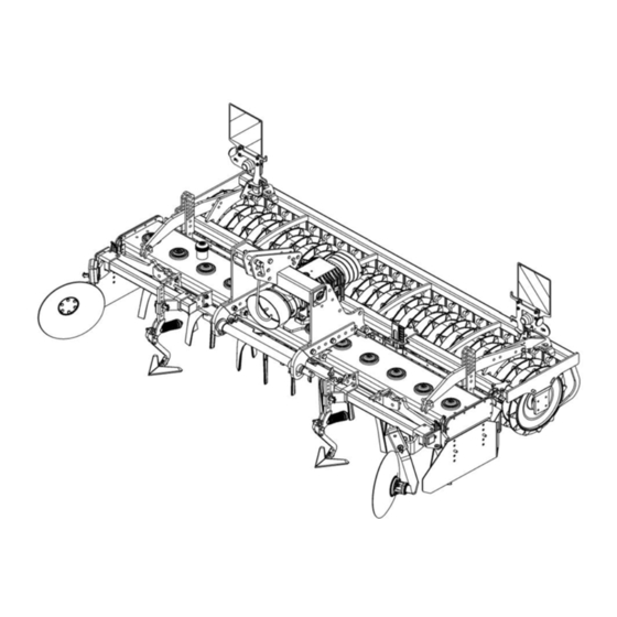
Layout and description LAYOUT AND DESCRIPTION Overview 1 Headstock 7 Manual gearbox 2 Tines 8 Roller 3 Wheelmark eradicators 9 Levelling bar 4 Feed discs 10 Gearbox 5 Lighting equipment 11 Three-point linkage, hydraulic (not 6 Rear PTO shown) - Page 38 Layout and description 12 Side shields 13 Side shield extension 14 Track markers 15 Protection bar for rotor shafts (stone protection)
-
Page 39: Description
Cross shaft L2/Z2 conforms to category 2. Cross shaft L3/Z3 conforms to category 3. Cross shaft L2/Z3 conforms to category 3N. Cross shaft Description Category Zirkon 12/300 3N, optionally 2 or 3 Zirkon 12/350 3N, optionally 3 Zirkon 12/400 3N, optionally 3... -
Page 40: Feed Disc
Layout and description 5.2.4 Feed disc The feed disc (1) prevents ridge formation and allows the next pass to be lined up ac- curately. 5.2.5 Lighting system The lighting system contributes significantly to increasing the safety of the imple- ment in road traffic. 5.2.6 Power takeoff shaft drive-through The rotational speed and direction of rota- tion for the power takeoff shaft drive-... -
Page 41: Rollers
Layout and description 5.2.8 Rollers The rollers reconsolidate the soil and provide additional crumbling. They carry the weight of the implement when it is lowered for operation during field work and en- sure accurate depth control. The implement can be fitted with different types of roller. -
Page 42: Side Blades
Layout and description 5.2.12 Side blades The height-adjustable side blades (1) and the extensions (2) prevent the outer tines from building up ridges. 5.2.13 Track markers The track markers mark out the track so that the driver has precise control on the next run. -
Page 43: Preparation Of The Tractor
Preparation of the Tractor PREPARATION OF THE TRACTOR Tyres The pressure - especially in the rear tractor tyres - must be equal. In heavy condi- tions it may be necessary to add wheel weights and/or water ballast. (See manu- facturer’s instructions). Lift Rods Adjust lift rods to equal length. -
Page 44: Hydraulic Equipment Required
Preparation of the Tractor Hydraulic equipment required The implement is supplied as standard with separate hydraulic connections for each consumer. The protecting caps on the hydraulic connections are coloured and the hydraulic connections themselves are marked alphanumerically. To activate the individual hydraulic devices listed below, the tractor must be equipped with the following spool valves: Consumer Connection... -
Page 45: Power Sources Required
Preparation of the Tractor Power sources required Damage to electrical components CAUTION The tolerance range for the power supply is between 10 V and 15 V. Overvoltages and undervoltages cause malfunctions and may destroy electrical and electronic components. Ensure that the power supply to the implement is always within the specified tolerance range. - Page 46 Preparation of the Tractor Loss of the implement The category of the tractor’s three-point linkage and the category of the cross shaft and top link pin must correspond. WARNING The cross shaft and top link pin may slip out of the connection if: ...
-
Page 47: Hydraulic System
Preparation of the Tractor Hydraulic system 6.8.1 Transport Lowering the three-point linkage CAUTION The device may be damaged if the three-point linkage of the trac- tor is lowered due to an incorrect setting or operation. For transport always switch the hydraulic system of the tractor to "position control". -
Page 48: Preparing The Implement
Preparing the implement PREPARING THE IMPLEMENT CAUTION Safety footwear must be worn when carrying out adjustment work. Before using the implement, always check all the safety devices to ensure that they are functioning correctly. They should always be used or operated in accord- ance with these operating instructions. -
Page 49: Wheelmark Eradicators
Preparing the implement Wheelmark eradicators The wheelmark eradicators (4) should be set to a depth which is approximately 5 cm below the surface of the wheel mark. They should always be slightly lower than the tines. See also the “Wheelmark eradicator settings”... -
Page 50: Attaching And Detaching The Implement
Attaching and detaching the implement ATTACHING AND DETACHING THE IMPLEMENT Before attaching and detaching the implement you must: DANGER Switch off the PTO and tractor engine. Apply the handbrake. Remove the ignition key. Coupling Risk of injury when coupling the device WARNING There is a risk of body parts being crushed between the tractor and device... - Page 51 Attaching and detaching the implement Risk of injury from unsecured top link pin If the top link pin is not secured, it may slip out or get lost. CAUTION As a result, the device may fall down or be damaged. ...
-
Page 52: Uncoupling
Attaching and detaching the implement Remove the PTO shaft from its holder (2). Connect the PTO shaft to the tractor PTO. Secure the PTO shaft protection (3) with the chain (4) to so that it cannot rotate. ... - Page 53 Attaching and detaching the implement Detach the hydraulic hose or hydraulic hoses. If a lighting system is mounted, remove the plug from the 7-pole socket of the tractor. Slide on the protective caps. Detach the upper control link from the implement. ...
-
Page 54: Tips For Travel On Public Roads
The power harrows Zirkon 12/400, 12/350 and 12/450 are wider than 3 m. On the Zirkon 12/300, 12/350 and 12/450 the side shields must be folded in before transport, see «Side blade, page 73». Installing the lighting equipment ... - Page 55 Tips for travel on public roads Tighten the star-shaped knob (4). Unroll the cable (3). Follow the same procedure for the other lighting unit (5). Insert the plugs (2) for the lighting equipment (1) into the relevant sockets.
-
Page 56: Feed Discs
Tips for travel on public roads Feed discs If feed discs are installed: Release the feed discs. Pull the feed discs out of the leg bracket. Turn the feed discs through 180°. Insert the feed discs into the leg bracket from above. ... -
Page 57: Track Markers
Tips for travel on public roads Track markers When transporting the implement on public roads, the track marker arms (5) must be folded and secured as follows so that they do not swing back: Positively connect the safety hooks (6) with the hose connection (7) on the hy- draulic ram (8). -
Page 58: Operation
Operation OPERATION 10.1 Removing the lighting equipment The lighting equipment (1) must be re- moved before the implement is used in the field, as follows: Pull out the plugs (2) for the lighting equipment (1). Roll up the cable (3). ... -
Page 59: Turning At The Headland
Operation 10.2 Turning at the headland DANGER Risk of damage to components If the implement is not fully raised, there is a risk of damage to components if turning at the headland is not carried out correctly. Before turning at the headland: ... -
Page 60: Settings
Settings SETTINGS Risk of accidents during adjustment work During all adjustment work on the implement there is a risk of crushing, cutting, trapping or knocking the hands, feet or body on heavy parts which may be under spring pressure and/or have sharp edges. -
Page 61: Cardan Shaft
Settings DANGER Switch off the power take-off before carrying out adjustment work. 11.1 Cardan shaft 11.1.1 General Attach the chains (4) to ensure that the cardan shaft protection (3) cannot rotate with the cardan shaft. The cardan shaft (5) must not be fully pushed together at any time during opera- tion. - Page 62 Settings If the cardan shaft (5) does not meet these requirements, for a cardan shaft (5) which is too long: 1. increase the distance between the power harrow and the tractor or 2. have the cardan shaft professionally shortened. If the cardan shaft is too short, reduce the distance between the power harrow and the tractor or use a longer cardan shaft from the same series.
-
Page 63: Changing The Distance Between The Implement And The Tractor
Settings 11.1.2 Changing the distance between the implement and the tractor Before changing the distance between the implement and the DANGER tractor, you must perform the following steps: Switch off the power take-off and tractor engine. Apply the handbrake. ... -
Page 64: Shortening The Cardan Shaft
Settings 11.1.3 Shortening the cardan shaft Pull the two cardan shaft halves apart. Hold the two cardan shaft halves against one another with the shortest possible gap between the tractor and the imple- ment. On the outer protective tube, mark the length you need to cut off. -
Page 65: Rpm Monitoring
Settings Hold the cut section of the inner protec- tive tube (2) over the inner profile tube (9) and cut off the inner profile tube (9) at right angles. Deburr and clean the outer and inner profile tubes. ... -
Page 66: Rotor Speeds
Settings 11.2.2 Rotor speeds The following rotor speeds are possible, depending on the power take-off speed: Variant 1 Variant 2 If the cardan shaft's overload coupling responds too quickly on non-stony ground, at a power take-off shaft speed of 540 rpm or 750 rpm, then the power take-off shaft speed of 1000 rpm with matching gear must be selected. - Page 67 Settings For a normal gearbox: Shifting lever (2) in position (3) = rotor speed 330 rpm with 1000-rpm power take- off speed. Shifting lever (2) in position (4) = rotor speed 440rpm with 1000-rpm take-off speed. For a slow gearbox: Shifting lever (2) in position (3) = rotor speed 330 rpm with 1000-rpm power take- off speed.
-
Page 68: Horizontal Position
Settings The recommended working speed for the rotor speeds is available in the following diagram. Recommended working speed depending on rotor speed Rotor speed per minute The rotor speed can be changed using the shifting lever. The 1000 rpm power take-off speed should always be selected. If a power take-off speed of 540 rpm or 750 rpm is used, then the input torque increases by 85 % or by 33 % and it does so at the same power transfer. -
Page 69: Working Depth
Settings If the power take-off and gearbox input shaft are not parallel, the cardan shaft rattles. This results in the following: Wear and damage to the cardan shaft, gearbox, and power take-off Premature response of the overload coupling on the cardan shaft 11.4 Working depth... -
Page 70: Hydraulic Adjustment
Settings 11.4.2 Hydraulic adjustment Hydraulic depth adjustment should always be carried out with the implement in the working position. Use the tractor spool valve to adjust the working depth via the hydraulic rams (1). Set the flow rate at the tractor spool valve to maximum. -
Page 71: Blade Tines
Settings 11.5 Blade tines The tines (1) can easily be replaced by hand as follows. Loosen the bolts (2). Fit new tines. Tighten all the bolts to a torque of 400 Nm. Check that all the tines are installed Tines are in the “drag”... -
Page 72: Blade Tines With A Quick-Change System
Settings 11.6 Blade tines with a quick-change system After the locking bar (2) has been re- leased, the tines (1) can be changed easily by hand using a no. 24 open- end wrench, as follows. Turn the locking bar (2) through 90° using an open-end wrench. -
Page 73: Change In The Direction Of Rotation Of The Rotors
Settings 11.7 Change in the direction of rotation of the rotors The direction of rotation may only be changed when the tractor power take-off is switched off and the tractor engine is at a standstill. The direction of rotation of the rotors with quick-change tines can be changed by moving the gearbox (1) to the side. - Page 74 Settings Check whether the discs (6) have locked in place. First, screw in all of the centring nuts (4) a little. Then tighten the centring nuts (4) with a tightening torque of 240 Nm. If the centring nuts (4) are not properly tightened, the tractor pow- er take-off must not be switched on.
-
Page 75: Side Blade
Settings 11.8 Side blade Move the side blade into the working position before working with it. The height of the spring-mounted side blades (2) is to be adjusted such that they cover the rotating tools completely. When worn they must be lowered accordingly. Once they have been lowered, tighten the bolts (3) again. -
Page 76: Retracting The Side Blades
Settings 11.8.1 Retracting the side blades For road transportation, the side blades (2) of the 3 m and 3.5 m wide rotary har- rows are to be retracted to ensure that the maximum permissible transport width is not exceeded. Remove the spring pin (7). ... -
Page 77: Extending The Side Blades
Settings 11.8.2 Extending the side blades Before the next work assignment and be- fore the tractor power take-off is switched on, the side blades (2) must be folded down as follows: Remove the spring pin (7) and guide pin (6). -
Page 78: Side Blade Extension
Settings 11.9 Side blade extension Bolt the side blade extensions (4) at the rear onto the side blades (2). After undoing the bolts (5) each side blade extension in the slots, under the washers (6), can be moved slightly forward or backward! The distance to the roller should be as small as possible. -
Page 79: Adjusting The Working Depth
Settings 11.10.2 Adjusting the working depth The wheelmark eradicators are set to ap- prox. 5 cm deeper than the bout of the tractor. Adjust the working depth of the wheelmark eradicator as follows: Raise the implement to relieve the load- ing on the wheelmark eradicator (1). -
Page 80: Feed Discs
Settings 11.11 Feed discs The feed discs (1) prevent damming, facilitating precision during the next run. Mount the feed disc (1) console (2) on the outside of the bracket (3). 11.11.1 Relocation at the side On the bracket (3), move the feed disc (1) to the required working width. - Page 81 Settings If the implement is retrofitted with a rear levelling beam (2), the roller (3) must be mounted at a greater distance from the implement. This also means that the straight protective bar (4) must be replaced by a curved protective bar. In the case of a retrofit with a seed drill, the roller must be moved backwards and a protective tube (1) must be fitted.
-
Page 82: Power Take-Off
Settings 11.13 Power take-off The tractor's power take-off may not be switched on until the rotary harrow has been lowered until it is only a few centime- tres above the ground and the side blades (1) prevent any penetration into the rotat- ing tools. -
Page 83: Levelling Beam
Settings 11.14 Levelling beam CAUTION Before adjusting the levelling beam, always move the side blade into the working position. The circular spike harrow can be equipped at the rear or front with a levelling beam (1). 11.14.1 Rear-mounted levelling beam Set the levelling beam (1) using the rough- turning gauge (2) so that the lower edge of the levelling beam is about 2 cm over the... -
Page 84: Track Markers
Settings 11.15 Track markers CAUTION Before using the track markers: Ensure that nobody is standing in the danger area. The track markers ensure that the power harrow lines up accurately for the next pass, particularly when used in conjunction with a seed drill. - Page 85 Settings Use the adjustment dimensions shown in the table below. The dimensions re- late to a marker groove in the middle of the tractor track. Distance from the centre of the seed Distance from outer seeding Zirkon drill to the marker groove coulter 12/300 300 cm...
-
Page 86: Shearing Protection
Settings 11.15.1 Shearing protection A shear bolt (9) protects the track marker against overloading. After a shear bolt has broken, the remains of the bolt must be removed and a new shear bolt fitted. Always use M10x45 / 8.8 shear bolts. -
Page 87: Rollers
Rollers ROLLERS 12.1 General The Zirkon can be fitted with a variety of rollers: Tube bar roller RSW 400 or RSW 540, Trapeze packer roller TPW 500, Trapeze disc roller TSW 500, Toothed packer roller ZPW 550 The tube bar rollers are maintenance-free. -
Page 88: Setting The Scrapers
Rollers 12.2 Setting the scrapers The adjustable scrapers (1) are adjusted by means of a bolt (2). Loosen the bolt (2). Set the bolt (3) to the position required. Tighten the bolt (2). See «Tightening torques, page 106». 12.3 Roller inclination If necessary, the inclination of trapeze rollers TPW and TSW and toothed packer... - Page 89 Rollers After adjusting the tilt: Check the position of the levelling bar. Re-adjust the levelling bar if necessary. See "Levelling beam , page 81".
-
Page 90: Mounting A Lemken Seed Drill
Mounting a LEMKEN seed drill MOUNTING A LEMKEN SEED DRILL 13.1 Coupling partsfor mounting a Solitair seed drill Zirkon circular spike harrows are available with coupling parts for attaching a Soli- tair seed drill. The coupling parts come with a top safety hook (1) and two lower support plates (2). -
Page 91: Coupling A-Frame
Mounting a LEMKEN seed drill 13.3 Coupling A-frame A corresponding coupling A-frame (4) is available for mounting seed drills equipped with a coupling A-frame. -
Page 92: Hydraulic Three-Point Linkage
Hydraulic three-point linkage HYDRAULIC THREE-POINT LINKAGE 14.1 Adjusting the hydraulic three-point linkage In order to optimise the centre of gravity when attaching an implement, e.g. a seed drill, the lower links (1) can be shortened by relocating them using the row of holes (2). -
Page 93: Mounting An Attachment
Hydraulic three-point linkage 14.2 Mounting an attachment WARNING Danger of tipping After setting the length of the upper link (8), secure the upper link with the locknut. Perform the following steps to mount an attachment: Pull out the spring pin (6). ... -
Page 94: Lowering The Attachment
Hydraulic three-point linkage With the attachment raised, close the shut-off valve (9). 14.3 Lowering the attachment Lower the attachment (seed drill) as fol- lows: Open the shut-off valve (9) with the trac- tor control unit locked. Switch the tractor control unit to the "Lower"... -
Page 95: Front Mounting
Front mounting FRONT MOUNTING 15.1 Front mounting headstock The front mounting headstock (4) is in- stalled at the rear of the power harrow headstock with a top link (5). The front mounting headstock (4) is recommended if the power harrow is always front-mounted. 15.2 Front-mounted tube bar roller A tube bar roller (6) is available for the 3 m implement for outstanding guidance of... -
Page 96: Switching Off The Device
Switching off the device SWITCHING OFF THE DEVICE 16.1 Shutting down the device in an emergency In an emergency shut down the device via the tractor. Switch the tractor engine off. Remove the ignition key. Damage caused by improper storage of the device If incorrectly or improperly stored, the device may be damaged, CAUTION e.g. -
Page 97: Maintenance And Repairs
Maintenance and repairs MAINTENANCE AND REPAIRS 17.1 Special safety instructions 17.1.1 General Risk of injury when carrying out maintenance and repair work There is always the risk of injury when carrying out maintenance and repair work. WARNING Use suitable tools, suitable climbing aids, platforms and support elements. -
Page 98: Immobilise The Implement For Maintenance And Repairs
Maintenance and repairs 17.1.4 Immobilise the implement for maintenance and repairs Risk of accidents when tractor starts up Injuries may occur if the tractor starts moving during maintenance and repair work. Switch off the tractor engine before carrying out any work on the WARNING implement. -
Page 99: Working Under The Raised Device
Maintenance and repairs 17.1.7 Working under the raised device Risk of accident due to lowering and extending of compo- nents and devices It is extremely dangerous to work under raised or next to retracted WARNING components and devices. Always secure the tractor to prevent it from rolling away. Re- move the ignition key and secure the tractor to prevent it from being started up by unauthorised persons. -
Page 100: Environmental Protection
Maintenance and repairs Risk of accident due to tool slipping off If applying a large force, e.g. when loosening bolts, the tool may WARNING slip off. This may result in hand injuries on sharp-edged parts. Avoid applying a large force by using suitable auxiliary equip- ment (e.g. -
Page 101: Check The Connections To The Tractor
Maintenance and repairs 17.3 Check the connections to the tractor 17.3.1 Hydraulic connections Risk of accidents due to escaping hydraulic fluid Hydraulic fluid which is ejected under high pressure (hydraulic oil) WARNING can penetrate the skin and cause serious injuries. In the event of injuries, consult a doctor immediately. -
Page 102: Maintenance Intervals
Replace damaged or defective hydraulic hoses im- mediately. The hydraulic hoses must be replaced 6 years after the date of manufacture at the latest. Only used hydraulic hoses approved by Lemken. Check that all safety equipment is functioning Safety equipment properly. -
Page 103: Oil Changing
Maintenance and repairs 17.5 Oil changing 17.5.1 Manual gearbox Before changing oil or checking the oil lev- el, the circular spike harrow must be parked on level and horizontal ground. Check the gearbox's oil level daily. The oil must always reach up to the check screw (2) for each gearbox. -
Page 104: Oil Change Intervals
Maintenance and repairs 17.5.2 Oil change intervals First oil change after 50 operating hours All other oil changes after 500 operating hours, but no later than once per an- Pay attention to cleanliness when changing oil. Dispose of drained oil in proper manner. -
Page 105: Gear Trough Fans
Maintenance and repairs The quantities of fluid grease required when changing the fluid grease are as fol- lows: Zirkon 12/300 33 kg 00 EP Zirkon 12/350 39 kg 00 EP Zirkon 12/400 44 kg 00 EP Zirkon 12/450 49 kg 00 EP ... -
Page 106: Lubrication
Maintenance and repairs 17.7 Lubrication The lubrication points should be lubricated with a multi-purpose grease in accord- ance with the maintenance schedule. Lubrication chart Every 25 Every 50 Before the winter After the winter break break operating hours a) Track marker disc bearings (2x) -
Page 107: Overview Of Lubrication Points
Maintenance and repairs 17.7.1 Overview of lubrication points Track marker disc bearing Swinging arm, track markers Feed disc Hydraulic three-point linkage Hydraulic depth adjustment rams... -
Page 108: Rotor Bearings
Maintenance and repairs 17.8 Rotor bearings The bearings of the rotors must be checked regularly fore play to prevent damage of the gears and the transmission pan. Check the bearings of the rotors up to 1000 operating hours every 200 operating hours ... -
Page 109: Bolts And Nuts Made Of Steel
Maintenance and repairs 17.9.2 Bolts and nuts made of steel Strength category Diameter 10.9 12.9 [Nm*] [Nm*] [Nm*] 13,6 16,3 23,4 32,9 39,6 M 10 46,2 64,8 77,8 M 12 80,0 M 14 M 16 M 20 M 24 1112 M 30 1314 1850... -
Page 110: Electrics
Maintenance and repairs 17.10.2 Electrics Visually inspect the connectors and cables. Visually inspect the lighting system. 17.11 Tines Worn tines are to be replaced in good time. Risk of accident when implement lowered Performing work under raised components/implements or next to WARNING swivelled-in components/implements is life-threatening. -
Page 111: Cardan Shaft
Porouse or defective hydraulic hoses must be changed immediately. Use hydraulic hoses only, which are accepted by Lemken! Important: Do not clean this implement with a Pressure Washer during the first 6 weeks. After this time a minimum nozzle distance of 60 cm must be... -
Page 112: Troubleshooting
Troubleshooting TROUBLESHOOTING Before carrying out troubleshooting, it is essential to ensure that CAUTION the implement is parked on the ground the power take-off and tractor engine are switched off the ignition key is removed. Only then can the fault be repaired. 18.1.1 General information Fault Cause... -
Page 113: Technical Data
TECHNICAL DATA TECHNICAL DATA Zirkon 12 Working width [mm] Number of rotors Weight [approx. kg] 1,035 1,149 1,261 Weight with toothed packer roller +451 +520 +589 +681 [approx. kg]... -
Page 114: Identification Plate
Identification plate IDENTIFICATION PLATE The identification plate (1) is situated on the front of the three-point tower. -
Page 115: Noise, Airborne Sound
Noise, Airborne Sound NOISE, AIRBORNE SOUND The noise level of the implement does not exceed 70 dB (A) during work. NOTES As the version of equipment is depending from the order, the equipment of your implement and its description concerned may deviate in some cases. To ensure a continuously updating of the technical features, we reserve the right to modify the design, equipment and technique. -
Page 116: Index
Index INDEX Axle loads ......................25 Blade tines ......................69 Cardan shaft ....................59, 109 Change in the direction of rotation of the rotors ............ 71 Coupling ....................... 48 Coupling A-frame ....................89 Coupling parts ...................... 88 Feed discs ......................78 FRONT MOUNTING ..................... - Page 117 Index Protective equipment .................... 78 Quick-change system ................... 70 REPAIRS ......................95 Roller inclination ....................86 Rollers ........................85 Rotor speeds ......................64 Rotors ........................71 RPM monitoring ....................63 Scrapers ......................47, 86 Seed drill ....................... 88 Shearing protection ....................84 Side blade ......................
Need help?
Do you have a question about the Zirkon 12 and is the answer not in the manual?
Questions and answers