Table of Contents
Advertisement
Quick Links
Advertisement
Table of Contents

Subscribe to Our Youtube Channel
Related Manuals for LEMKEN Diamant 16


Summary of Contents for LEMKEN Diamant 16
- Page 1 Operating Instructions Semi-Mounted Reversible Plough Diamant 16 - 16V - en - Item no. 17512309 BA 00/07.18 LEMKEN GmbH & Co. KG Weseler Straße 5, 46519 Alpen / Germany Telephone +49 28 02 81 0, Fax +49 28 02 81 220...
- Page 3 However, this brief instruction is not a substitute for thorough study of the operating instructions. These operating instructions will help to familiarise you with the LEMKEN GmbH & Co. KG device and the options available for using it.
- Page 4 Remember that you should only use genuine LEMKEN spare parts. Reproduction parts have a negative influence on the function of the device, have a shorter ser- vice life and present risks and hazards that cannot be estimated by LEMKEN GmbH & Co. KG. They also increase the maintenance costs.
-
Page 5: Table Of Contents
CONTENTS General information ....................9 Liability ........................... 9 Guarantee ........................9 Copyright ........................10 Optional accessories ....................10 Type plate ........................11 Symbols used in the Operating Instructions ............14 Hazard classes ......................14 Information........................14 Environmental protection ................... 14 Indication of passages .................... - Page 6 Operation on public highways ................... 30 3.9.1 Lighting system and identification ................30 3.9.2 Requirements of the tractor ..................30 3.9.3 Check before departure ..................... 31 3.9.4 Correct behaviour in road traffic ................31 3.10 Obligation of the operator ..................32 3.11 Safe use of the implement ..................
- Page 7 Preparing the implement ..................47 Headstock attachment position ................. 47 Length of the stand ..................... 48 Implement with traction increase device ..............49 Attaching the implement ..................50 General ......................... 50 Work instruction ......................52 Uncoupling the implement ..................56 Adjust the length of the stand ..................
- Page 8 12 Adjustments......................76 12.1 Front furrow width ....................... 77 12.2 Spacing from the tractor to the edge of the furrows (only for on-land version) ..78 12.3 Working depth ......................79 12.4 Tilt ..........................82 12.5 Working width per element (Diamant) ............... 83 12.6 Working width for each body (Diamant V) ..............
- Page 9 13 Overload safety devices ..................107 13.1 Shearing protection ....................107 13.2 Hydromatic hydraulic overload protection ............. 109 13.2.1 General information ....................109 13.2.2 Setting the release force ..................110 13.2.3 Depressurising the hydraulic system ..............115 13.2.4 Pressurising the hydraulic system ................ 119 14 Attachment arm .....................
- Page 10 17.5 Check the connections to the tractor ..............132 17.5.1 Hydraulic connections ..................132 17.5.2 Electrical connections ................... 132 17.6 System pressure of the traction increase device ........... 133 17.6.1 Reading the system pressure ................133 17.6.2 Change system pressure ..................134 17.8 Lubrication .........................
-
Page 11: General Information
Co. KG, in particular Section IX, shall apply. Liability. In line with the dimensions cited in these conditions the LEMKEN GmbH & Co. KG shall not be held liable for any personal or material damage, when such damage is caused by one or more of the following reasons: ... -
Page 12: Copyright
Infringements will result in a claim for damages. Optional accessories LEMKEN implements may be equipped with various accessories. The operating instructions below describe both series components and optional accessories. Please note: These accessories will vary depending on the type of equipment. -
Page 13: Type Plate
General information Type plate The implement carries a type plate. The type plate can be found at front right on the implement. The operating instructions may apply to different implement types or variants of the implement. The operating instructions indicate infor- mation which only applies to a specific im- plement type or a specific variant of the implement. - Page 14 General information 1 Series 2 Type designation 3 Serial number 4 Year of manufacture 5 Permissible drawbar load [kg] 6 Permissible axle load [kg] 7 Permissible gross weight [kg] 8 Company logo and address 9 CE marking (only within the European Union) 10 Name of manufacturer 11 Type, variant, version 12 Type approval date...
- Page 15 General information Figure: Example of a type plate, implements with EU type approval 1 Series 2 Type designation 3 Serial number 4 Year of manufacture 5 Permissible drawbar load [kg] (axle 0) 6 Permissible axle load [kg] (axle 1) 7 Permissible axle load [kg] (axle 2) 8 Permissible gross weight [kg] (without specification) 9 Company logo and address...
-
Page 16: Symbols Used In The Operating Instructions
Symbols used in the Operating Instructions SYMBOLS USED IN THE OPERATING INSTRUCTIONS Hazard classes The following symbols are used in the Operating Instructions for particularly im- portant information: DANGER Denotes an imminent hazard with high risk, which will result in death or severe physical injury, if not avoided. -
Page 17: Indication Of Passages
Symbols used in the Operating Instructions Indication of passages The following symbols are used for particular passages in the operating instruc- tions: Indicates work steps Indicates enumerations... -
Page 18: Safety Measures And Precautions
Safety measures and precautions SAFETY MEASURES AND PRECAUTIONS General safety instructions for the operator are specified in the chapter entitled «Safety measures and precautions». At the start of some main chapters the safety instructions, which refer to all work to be carried out in this chapter, are listed to- gether. -
Page 19: Safety Features Of The Device
Safety measures and precautions Clarify questions of comprehension concerning the contents of these operating instructions before starting work. To do this, contact the LEMKEN sales partner if required. Safety features of the device To protect the operator and the device, the device is equipped with special safety features in accordance with country specific requirements. - Page 20 Safety measures and precautions Stand Protection against unauthorised use: Cross shaft...
-
Page 21: Safety And Warning Signs
Safety measures and precautions Safety and warning signs 3.4.1 General information The implement features all equipment which ensures safe operation. If hazardous areas could not be completely secured with respect to operational safety, warning signs are affixed which indicate these re- sidual risks. -
Page 22: Meaning Of Warning Signs
Safety measures and precautions 3.4.3 Meaning of warning signs Please familiarise yourself with the meaning of the warning signs. The following explanations provide detailed information. Please read and observe the operating in- structions and safety instructions before starting up the implement for the first time. Before carrying out maintenance or repair work, switch off the engine and remove key. - Page 23 Safety measures and precautions Area between tractor and implement A running tractor may cause or initiate un- intentional movements. This will result in death or serious injuries. When the tractor is running: Do not remain in the area between the tractor and implement.
-
Page 24: Meaning Of Other Symbols
P0 / T0 Hydromatic - comfort version P1 / T1 Rotary mechanism (OF-reverse rotation) P2 / T2 Hydraulic working width adjustment (only Diamant 16 V / 16 VT) P3 / T3 / T Depending on the equipment: Jockey wheel / Hydromatic standard ver-... - Page 25 Safety measures and precautions Scale for depth adjustment Working depth alteration per gradua- tion: 5 cm Maximum working depth: 33 cm (with a frame height 80 cm)
-
Page 26: Special Safety Instructions
Safety measures and precautions Special safety instructions Risk of injury due to non-observance of the currently valid occupational safety guidelines If the currently valid occupational safety guidelines are bypassed WARNING or safety equipment is rendered unusable when handling the de- vice, there is a risk of injury. - Page 27 Safety measures and precautions Risk of injury when freeing casualties When rescuing people trapped or injured by the device, there is a risk of additional serious injury to the casualty if the hydraulic con- nections were not connected according to their colour coding as described in the section entitled "Required hydraulic equipment".
- Page 28 Safety measures and precautions Risk of injury on parked implement WARNING The implement is not a toy! Climbing onto the parked implement can result in severe injuries, e.g. due to slipping or tripping. Do not climb onto the parked implement.
-
Page 29: Danger Areas
Safety measures and precautions Danger areas 3.6.1 Danger areas during implement operation Moving danger area The danger area around the implement moves with the implement during operation. The danger area includes the area extending across the entire width (a) of the implement in the direction of WARNING travel. -
Page 30: Residual Risks
Safety measures and precautions Residual risks Residual risks are particular hazards which occur when handling the device and which cannot be eliminated despite a design in accordance with safety require- ments. Residual risks are not usually obvious and may be the source of a potential injury or health hazard. -
Page 31: Hazards Of Hydraulic Systems
Safety measures and precautions 3.7.2 Hazards of hydraulic systems There is a risk of burn injuries and contamination with hydraulic oil, particularly of the face, eyes and unprotected skin: when hot/pressurised hydraulic oil escapes from leaking connections or hoses ... -
Page 32: Operation On Public Highways
Safety measures and precautions Operation on public highways 3.9.1 Lighting system and identification A proper lighting system, identification and equipment must be on the device if it is to be transported on public roads. Further information can be requested from the appropriate authorities. -
Page 33: Check Before Departure
Safety measures and precautions 3.9.3 Check before departure Prior to trips with unit extended lock the control lever for the three-point power- lift. Align top links roughly parallel with the lower links. In conjunction with the traction booster, set the headstock as vertical as possi- ble. -
Page 34: Obligation Of The Operator
Safety measures and precautions 3.10 Obligation of the operator Before switching on the device, read the operating instructions. Follow the safety instructions! Wear appropriate protective clothing when carrying out any work on the device. Protective clothing must be tight-fitting! ... - Page 35 Safety measures and precautions Always attach the implement correctly and only attach it to the equipment pro- vided for that purpose. Always take great care when attaching the implement to and detaching it from the tractor. There is a risk of injury due to crush and shear points in the area around the three-point linkage.
-
Page 36: Personnel Selection And Qualifications
Safety measures and precautions 3.11.2 Personnel selection and qualifications The tractor driver must have the appropriate driving licence. All work on the implement must be carried out by properly trained and instructed personnel. The personnel must not be under the influence of drugs, alcohol or medication. -
Page 37: Handing Over The Implement
Handing over the Implement HANDING OVER THE IMPLEMENT As soon as the implement is delivered, ensure that it corresponds with the order package. Also check the type and completeness of any supplied accessories. When the device is handed over, your dealer will explain how it works. ... -
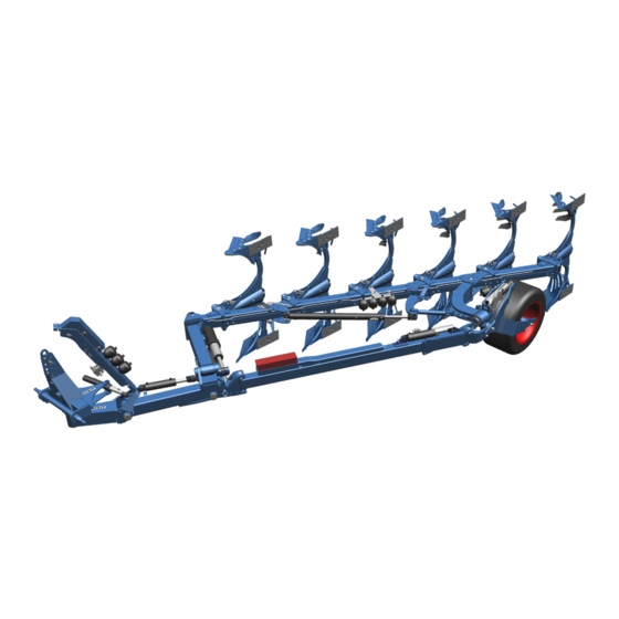
Page 38: Layout And Description
Layout and description LAYOUT AND DESCRIPTION The following assembly groups may be installed on the imple- ment, depending on implement model and national requirements. Overview Operating position 1 Headstock 7 Frame 2 OptiLine adjustment sys- 8 Plough body 9 Additional tools Fertiliser feeders 3 Hydraulic cylinder for (insertion hand, disc coulters not pictured) traction booster... -
Page 39: Description
Layout and description Description 5.2.1 Headstock The headstock with top link bolt and cross shaft complies with the ISO 730 stand- ard and is used to connect the implement to the three-point linkage of the tractor. Cross shaft L2/Z3 complies with category 3N. Cross shaft L3/Z3 complies with category 3. -
Page 40: Rotary Cylinder
Layout and description 5.2.4 Rotary cylinder Two telescopic cylinders (3) ensure that the implement rotates smoothly. 5.2.5 Stabiliser The stabiliser (4) guides the wheel and carries and pulls the frame. 5.2.6 Depth wheel Low ground pressure during ploughing through large, deep-tread depth wheel. -
Page 41: Frame
Layout and description 5.2.7 Frame The frame supports the plough body. Diamant: four working width settings Diamant V: hydraulically infinitely adjust- able working width... -
Page 42: Plough Body
Layout and description 5.2.8 Plough body DuraMaxx The strips (1) or mould boards (2) are at- tached to the mould board (4) with hooks (3). Accordingly, replacement without tools is possible. - Page 43 Layout and description Dural The plough body consists of: Mouldboard, made up of a shin (1) and a mouldboard (2), or slats (5). Share, made up of a wing (3) and a point (4). Frog (6) Landside (7)
-
Page 44: Additional Tools
Layout and description 5.2.9 Additional tools The following additional tools are available as accessories: Trashboard (1) Skimmer (2) Sword coulter (3) - Page 45 Layout and description Disc coulter (4) Version with smooth disc coulter (4), rigid leg (5). Version with toothed disc coulter (6), spring-loaded leg (7). Version with coulter (8) smooth, length- ways adjustable rigid stalk (9)
-
Page 46: Preparations On Tractor
Preparations on tractor PREPARATIONS ON TRACTOR Tyres The air pressure must be identical, particularly on the rear tractor tyres. Under dif- ficult conditions, additional wheel weights should be used or the tyres topped up evenly with water. Refer to the operating instructions from the tractor manufactur- Lifting rods On implements with a three-point connection the lifting rods on the tractor's three- point linkage should be set to the same length using the adjustment device and... -
Page 47: Power Sources Required
Preparations on tractor Power sources required Damage to electrical components CAUTION The tolerance range for the power supply is between 10 V and 15 V. Overvoltages and undervoltages cause malfunctions and may destroy electrical and electronic components. Ensure that the power supply to the implement is always within the specified tolerance range. -
Page 48: Hydraulic Equipment Required
Preparations on tractor Hydraulic equipment required The implement is supplied as standard with separate hydraulic connections for each consumer. The cover flaps for the hydraulic connections are colour-coded and the hydraulic connections themselves are alphanumerically coded. For operation of the specific hydraulic equipment, the tractor must be equipped with the following spool valves: Consumer Single acting... -
Page 49: Preparing The Implement
Preparing the implement PREPARING THE IMPLEMENT Headstock attachment position Swivelling the headstock (2) allows the dis- tance between the plough’s pivot point and the tractor’s rear axle to be increased or reduced respectively. The distance must be kept as small as possible to minimise the side pull. -
Page 50: Length Of The Stand
Preparing the implement Length of the stand The stand (1) must be so mounted length- ways that when the implement is parked in the working position the cross shaft is par- allel to the ground. The length can be adjusted with device at- tached to the tractor, Adjust the length of the stand see ",56 page ". -
Page 51: Implement With Traction Increase Device
Preparing the implement Implement with traction increase device The headstock (2) is connected to the plough frame by a joint. When a traction increase device is installed, it is also con- nected by a hydraulic ram (5). So that the plough can be attached and removed from the tractor safely, the pres- sure supply to the hydraulic ram is inter- rupted by the shut-off valve (4). -
Page 52: Attaching The Implement
Attaching the implement ATTACHING THE IMPLEMENT General Risk of injury when coupling the device WARNING There is a risk of body parts being crushed between the tractor and device The tractor must be secured against unintentionally rolling away. Never actuate the hydraulic system of the tractor if there are people between the tractor and device. - Page 53 Attaching the implement...
-
Page 54: Work Instruction
Attaching the implement Work instruction Switch the tractor's hydraulic system to position control mode. Move the tractor straight back in front of the implement. o The lower links are positioned in front of the cross shaft. o Headstock is positioned as far possible with the cross shaft to the rear. - Page 55 Attaching the implement Unlock the stand (6). To do this, turn handle of spring lock (7). Lift the stand (6) and secure it with spring lock (7). o Make sure that the spring lock (7) clicks into place in borehole (8) . ...
- Page 56 Attaching the implement Rotate the plough to the left-turning posi- tion. Install tilt adjustment screw (5) for right- turning side. o So that the adjustment screw (5) can be inserted into the holder, bend the spring leg downwards, as shown. When the screw is installed, the spring leg locks it in place.
- Page 57 Attaching the implement Align the lower edge of the stabiliser parallel to the ground. o Keep a 400 mm clearance to the ground.
-
Page 58: Uncoupling The Implement
Uncoupling the implement UNCOUPLING THE IMPLEMENT Risk of injury when detaching the implement WARNING There is a risk of crushing body parts between the tractor and im- plement. Secure the tractor to prevent it from rolling away accidentally, oth- erwise there is a risk of crushing. Never activate the tractor hydraulic system if somebody is stand- ing between the tractor and the implement. -
Page 59: Work Instruction
Uncoupling the implement Work instruction Rotate the plough to the left-turning posi- tion. Remove the screw (1) of the angular ad- justment for the right-hand side. The screw (1) for the right-turning side is stored in the toolbox when not in operation. - Page 60 Uncoupling the implement Lower the lower link until the stand is on the ground. Unlock and disconnect the top link bolt (4). Insert the top link bolt into the borehole (5) of the joint at the stabiliser. The top link bolt prevents the headstock from being lowered too far when the -...
- Page 61 Uncoupling the implement Implement with traction increase device: When the implement is detached, depres- surise the traction increase device. Use the appropriate spool valve to raise the lower link. Release pressure as follows via the spool valve of the depth wheel: The shut-off valve (6) is open.
- Page 62 Uncoupling the implement Disconnect the hydraulic hoses from the tractor. Install the protecting caps. Position the top link in the tractor-sided holder. See operating instructions from the tractor manufacturer. Remove lower link from the cross shaft (2).
-
Page 63: Driving On Public Highways
Driving on public highways DRIVING ON PUBLIC HIGHWAYS 10.1 General information A proper lighting system, identification and equipment must be on the implement, if it is to be transported on public roads. The country-specific valid laws and regu- lations pertaining to driving on public roads must be observed. 10.2 Preparation for driving on public roads Before commencing a journey on public roads, the following components and... - Page 64 Driving on public highways Open shut-off valve (3) of the damper (4). o Shock absorption is activated. To ensure sufficient spring travel, set 3 cm spacingbetween fork (5) and stop (6). o The fork (5) must be able to move freely .
- Page 65 Driving on public highways Align the stabiliser parallel to the ground. o The clearance from the lower edge of the stabiliser to the ground must be 400 mm. Secure the following controls of the trac- tor against unintentional operation: o Turnover device o Working width adjustment o Depth adjustment...
-
Page 66: Transport
Driving on public highways 10.3 Transport 10.3.1 Permitted transport height The implement may be too high. This means there is an increased WARNING danger under bridges, driveways and high-voltage lines. The maximum permissible transport height is 4 m. o Make sure that the maximum permissible transport height of 4 m is not exceeded. -
Page 67: Lighting Equipment And Signs
Driving on public highways 10.4 Lighting equipment and signs 10.4.1 General Before travelling on public roads, the appropriate lighting equipment and signs must be installed in accordance with national regulations. 10.4.2 Attaching the lighting equipment Rotate the frame to the half-rotated posi- tion = centre position ... - Page 68 Driving on public highways Plug connector (6) of the cable into socket (7) on the device. The lighting system must be disassembled during the turning pro- cess and when working in the field. Otherwise there is a risk of damaging the implement.
-
Page 69: Checking The Lighting Equipment
Driving on public highways 10.4.3 Checking the lighting equipment Activate the direction indicators in the tractor. If the tell-tale light for the direction in- dicator on the tractor (5) and the tell-tale light for the direction indicator on the im- plement (6) flash, the lighting equipment has been connected correctly. -
Page 70: Operation
Operation OPERATION 11.1 Rotating the frame Refer to the safety and protective measures, see page 16. DANGER Before each rotation, ensure that there are no persons in the turning and swivelling area of the plough. Only operate the slewing gear from the tractor seat. ... - Page 71 Operation sition = second pressure position. Set the spool valve to T for the depth wheel. Continue to pressurise until the previ- ously set level of system pressure for the traction increase device been achieved. o The indicator at the pressure gauge (1) rises to the previous- ly set level of system pressure.
-
Page 72: On-Land Ploughing (Of)
Operation 11.2 On-land ploughing (OF) DANGER Ensure that the general health and safety precautions are tak- en, see page 16. 11.2.1 General The implements are also available in an on-land version. This version of the im- plement can be used for both on-land (O) and in-furrow (F) ploughing. O ploughing = Use on land behind a crawler or a tractor F ploughing = Use in the furrow behind a tractor Before the implement can be switched between the two modes,... - Page 73 Operation Open the valves (6) on the hydraulic ram (5). Raise the front and rear of the frame slightly so that the plough bodies are no longer touching the ground. Using the spool valve that is used to turn the frame, fully extend the hydraulic ram (5) to move the plough into the on-land position.
-
Page 74: Converting From O Operation To F Operation
Operation 11.2.3 Converting from O operation to F operation Close the valves (3) on the turnover ram (4). Open the valves (6). Raise the front and rear of the frame slightly so that the plough bodies are no longer touching the ground. - Page 75 Operation Turn the frame to the centre position. Swivel the depth wheel (8) to the central position. Push the stop (7) against the direction of the arrow until the nose (11) of the con- sole (12) engages in the recess (13) in the stop (7).
-
Page 76: Turning On The Headland
Operation 11.3 Turning on the headland DANGER Risk of damage to components If an implement is not raised all the way, there is a risk of damage to components if the tractor is not turned correctly at the headland. Before turning at the headland, the implement must be raised all the way before cornering in order to prevent damage to the implement. -
Page 77: Damper On The Depth Wheel
Operation 11.4 Damper on the depth wheel Working in the field Close shut-off valve (2) of the damper (1). o Shock absorption is disabled. On public roads Open shut-off valve (2) of the damper (1). o Shock absorption is activated. ... -
Page 78: Adjustments
Adjustments ADJUSTMENTS Read and follow the section entitled "Safety and protection measures. CAUTION The implement may only be used, maintained and repaired by people who are familiar with it and who are aware of the haz- ards involved. ... -
Page 79: Front Furrow Width
Adjustments 12.1 Front furrow width Manual adjustment with turnbuckle (1) Front furrow too narrow: Turn the turnbuckle (1) longer. Front furrow too wide: Turn the turnbuckle (1) shorter. Hydraulic setting with hydraulic cylin- der (2) Front furrow too narrow: ... -
Page 80: Spacing From The Tractor To The Edge Of The Furrows (Only For On-Land Version)
Adjustments 12.2 Spacing from the tractor to the edge of the furrows (only for on-land version) In on-land operation the distance between the tractor and the edge of the furrow is adjusted by a turnbuckle (1) or a hydraulic cylinder (2). Manual adjustment with turnbuckle (1) Distance too small: ... -
Page 81: Working Depth
Adjustments 12.3 Working depth The implement is equipped with a hydrau- lic depth adjustment on the depth wheel. Depending on the equipment, the depth adjustment is hydro-mechanical or hydro- electrical. Hydro-mechanical depth adjustment Lower the plough to the working depth currently set. - Page 82 Adjustments Hydro-electrical depth adjustment Lower the plough to the working depth currently set. Use the control to switch the solenoid valve (3) on the lifting cylinder to "SET". To set the desired working depth, lift or lower the depth wheel using the auxiliary control device of the tractor.
- Page 83 Adjustments On-land version of the implement In on-land operation, the working depth is set in addition on the front jockey wheel. Release the stop (4). Move the stop (4). Push the stop in the direction of the ar- =>...
-
Page 84: Tilt
Adjustments 12.4 Tilt During work, the stalks of the body should be more or less vertical in relation to the ground when looking in the direction of travel. The tilt is set correctly if the plough looks to be even. If it does not, the tilt can be adjusted as fol- lows using the screws (1) on both sides: ... -
Page 85: Working Width Per Element (Diamant)
Adjustments 12.5 Working width per element (Diamant) The working width has four adjustments. Clearance Working width between per element [cm] elements (cm) The working width change is made by ad- justing the individual elements. Undo the screw (1). Dismount screw (2). ... -
Page 86: Working Width For Each Body (Diamant V)
Adjustments 12.6 Working width for each body (Diamant V) The working width of the Diamant V is infi- nitely adjustable. Clearance between Adjustment range per elements element [cm] (cm) 30 – 55 30 – 60 The working width alteration is made by adjusting the hydraulic cylinder (1). -
Page 87: Side Pull
Adjustments 12.7 Side pull Set the tractor's three-point linkage for the work. The recommended distance between the tractor’s rear wheels in furrow mode is roughly 1.3 m - 1.5 m. The side pull to the ploughed side can be reduced by increasing the distance be- tween the tractor’s rear wheels. - Page 88 Adjustments The OptiLine pressure gauge (3) displays the current operating pressure of the Op- tiLine setting system. Sideways pull - tractor pulls in the di- rection of the ploughed surface: Increase the pressure in the OptiLine system until the tractor runs straight without counter-steering.
-
Page 89: Traction Point Height (Only For On-Land Version)
Adjustments 12.9 Traction point height (only for on-land version) When using the device with crawler trac- tors with only one set of tracks on each side: Make sure while working that the run- ning gear applies the same ground pres- sure over the entire length. -
Page 90: Pitch Angle
Adjustments 12.10 Pitch angle 12.10.1 DuraMaxx plough body The pitch angle is adjusted via the position of the eccentric plate. The bodies are fitted at a centre pitch angle relative to the ground. The eccentric plate (1) is in the centre position, see notch on the eccentric plate. - Page 91 Adjustments Smaller pitch angle: Rotate eccentric plate (1) upwards by 90°. Notch points in the direction of the plough frame. o Improved depth control. After adjusting the pitch angle, tighten nuts (2) and (3). Tightening torques see «Tightening torques, page 130»...
-
Page 92: Dural Plough Body
Adjustments 12.10.2 DURAL plough body The bodies are fitted at a centre pitch - angle relative to the ground. If required, the pitch angle can be changed using the two adjusting screws (1a, 1b). Undo the screw (2). The bolted connection (3) is used as a piv- ot when adjusting the pitch angle. - Page 93 Adjustments All plough bodies must be adjusted to the same pitch angle. Adjust pitch angle of the first and last plough body. Measure distance between point and plough frame (= reference dimension) Adjust the remaining plough bodies ac- cording to this reference dimension.
-
Page 94: Landside
Adjustments 12.11 Landside For better guidance on slopes, move land- side DMV1 (1) to a lower position (only possible with DuraMaxx plough bodies.) Loosen the bolt Remove the bolt (2). Move the landside (2) to the lower posi- tion. -
Page 95: Sword Coulter
Adjustments 12.12 Sword coulter The landside wedge must be removed be- fore the sword coulter is attached. Unscrew countersunk screw (5) and hexagon bolt (4). Remove landside wedge (1) and hexa- gon bolt (4). Attach sword coulter (2) in front of the landside (3) and screw into place using both hexagon bolts (5). -
Page 96: Trashboard
Adjustments 12.13 Trashboard DuraMaxx version Align trashboard (1) with holder (2) via the slots (4) and screw onto the leg (3). All trashboards must be set in the same position. - Page 97 Adjustments Dural version Align trashboard (1) with holder (2) via the slots (4) and screw onto the mould- board (3). Adjust trashboard to prevent crop resi- due between the slats or mouldboard and trashboard o The edge of the trashboard is positioned on the mouldboard or mouldboard slat.
- Page 98 Adjustments The support bolt (4) supports the trash- board against the leg. Secure support bolt (4) with lock nut (5), see view Y. The installation position of the support bolt and the lock nut may vary de- pending body shape used.
-
Page 99: Subsoilers
Adjustments 12.14 Subsoilers Subsoilers are mounted to the basic body and to the leg at DuraMaxx and Dural re- spectively. The depth of the subsoilers can be adjusted. The leg (2) is protected against wear by the leg guard (3). Both the leg guard (3) and the gudgeon (1) can be replaced after removing the nut (4). -
Page 100: Wide Furrow Cutter
Adjustments 12.15 Wide furrow cutter The wide furrow cutter (1) widens the fur- row made by the last body. It can be used in light to medium soils without any prob- lems. It cannot be used effectively in heavy soil conditions. The wide furrow cutter (1) is attached to the last body on the plough. -
Page 101: Skimmers
Adjustments 12.16 Skimmers 12.16.1 General information The skimmers (1) should penetrate the soil by approx. 5 - 10 cm and in the top view are approx. 2 to 3 cm from the side of the landside on the plough body. If you want to plough e.g. -
Page 102: Working Depth
Adjustments 12.16.2 Working depth Risk of crushing CAUTION When adjusting the working depth, the skimmer can drop down after removal of the guide pin (4). Hold skimmer firmly with one hand until it is secured by insert- ing the guide pin (4). When adjusting the working depth, the projection anglesetting does not change. -
Page 103: Projection Angle Adjustment
Adjustments 12.16.4 Projection angle adjustment On the standard version the projection an- gle of the skimmers cannot be adjusted. On the version with projection angle ad- justment the skimmers (1) are connected to their flat stalks (2) and the swivel brack- et (3) is connected by a pivot to the bracket (4). -
Page 104: Disc Coulters
Adjustments 12.17 Disc coulters 12.17.1 General information The disc coulters have been set for operation at the factory with the following ad- justment dimensions. Make subsequent adjustments to the disc coulters only when changing the setup state. The working depth (T) of the disc must be set between 7 cm and 12 cm. -
Page 105: Working Depth
Adjustments 12.17.2 Working depth The working depth of the disc coulter is ad- justed as follows: Undo the screw (2). Swivel coulter arm (1) as required. Rigid disc coulter Ensure that the teeth on the coulter arm (1) mesh exactly with the adjacent toothed bracket (3) before tightening the screw (2). -
Page 106: Side Distance
Adjustments 12.17.3 Side distance The lateral clearance between the coulter disc (1) and the landside on the plough body is adjusted by swivelling the coulter stalks (2). Undo the screw (3). Adjust lateral clearance. Move coulter stalk (2) in the slot (a) until the required position has been reached. -
Page 107: Swivel Restriction
Adjustments 12.17.4 Swivel restriction The lateral swivel area of the disc coulters (1) is restricted by the adjusting piece (2). The adjusting piece must be adjusted so that the disc coulter, when swivelled in, is parallel with the landside of the plough body at a distance of 2 cm to 3 cm. -
Page 108: Jockey Wheel
Adjustments Spring-loaded disc coulter (version T) Version without skimmer o Adjust the adjusting piece so that the disc coulter, when swivelled in, points towards the point on the plough body. 12.18 Jockey wheel In the on-land version, the Jockey wheel (1) is supplied in the scope of delivery. -
Page 109: Overload Safety Devices
Overload safety devices OVERLOAD SAFETY DEVICES 13.1 Shearing protection The plough bodies release upwards when the shear bolt is over- loaded. Never stand in the release area of the plough bodies while WARNING ploughing and/or performing maintenance work. Always ensure that there is adequate safety clearance. Risk of crushing! Moving parts in the area of the shearing protection may cause crushing and shearing injuries. - Page 110 Shear bolt Plough type Dimension Diamant 16 M14 x 85 - 10.9 M 16 x 100 LS 70 X 25 - 12.9 Diamant 16 V Diamant 16 T M 14 X 70 LS 51 x 15 - 10.9 Diamant 16 VT...
-
Page 111: Hydromatic Hydraulic Overload Protection
Overload safety devices 13.2 Hydromatic hydraulic overload protection Read and observe the information in the "Safety and protective measures" section and the specific safety notice "Danger from hydraulic systems". Never stand in the plough elements danger zone while plough- ing work is in progress! DANGER The plough elements release upwards when overloaded. -
Page 112: Setting The Release Force
Overload safety devices 13.2.2 Setting the release force The hydraulic overload protection enables various operating pressures to be set; a low operating pressure should be selected for flat and easy ground conditions and a higher pressure for difficult ground conditions. Standard equipment A shut-off valve (1) is located below the pressure gauge (2). - Page 113 Overload safety devices To increase pressure: set the control unit for the depth wheel to P; the depth wheel is raised Open shut-off valve (1a), see figure. The pressure gauge (2) display indicates the final pressure as soon as the - depth wheel is lifted.
- Page 114 Overload safety devices Lower pressure: set the control unit for the depth wheel to T; the depth wheel (3) is lowered Open shut-off valve (1a). The pressure gauge (2) display indicates the final pressure as soon as the depth wheel is lowered.
- Page 115 Overload safety devices After connecting the adjusting valve unit (1) to a spool valve on the tractor, the sys- tem is ready to operate with the factory set maximum and minimum operating pres- sure. If necessary, these operating pres- sures can be individually adjusted using the rotary knobs (2) and (3) and read from the pressure gauge (4): ...
- Page 116 Overload safety devices Setting the minimum operating pressure: Increasing the minimum operating pres- sure: Turn the rotary knob (3) clockwise. Reducing the minimum operating pressure: Turn the rotary knob (3) anti-clockwise. While working, the tractor control unit must be switched to float position, otherwise overload protection is not guaranteed if several plough elements are released simultaneously.
-
Page 117: Depressurising The Hydraulic System
Overload safety devices 13.2.3 Depressurising the hydraulic system Always depressurise the hydraulic system before performing maintenance or re- pair work, for instance. To do so, pressure must be released via the spool valve of the depth wheel as follows. Risk of injury due to incorrectly performed maintenance work DANGER Incorrect maintenance and repair work jeopardise operational safety. - Page 118 Overload safety devices Equipment without traction increase device Set the spool valve to P. o The depth wheel is raised. Set the chassis to the lowest working depth to ensure the plough bodies with overload safety device have sufficient clearance to the ground and can be low- ered after releasing the pressure.
- Page 119 Overload safety devices Equipment with traction increase device: Release pressure in the traction in- crease device as follows via the spool valve of the depth wheel: The shut-off valve (1) is open. Set the spool valve for the depth wheel to P and keep hold of it until the pres- sure gauge indicator (2) drops to 0 bar.
- Page 120 Overload safety devices Equipment with comfort valve (4) Set the spool valve to P. o The depth wheel is raised. Set the chassis to the lowest working depth to ensure the plough bodies with overload safety device have sufficient clearance to the ground and can be low- ered after releasing the pressure.
-
Page 121: Pressurising The Hydraulic System
Overload safety devices 13.2.4 Pressurising the hydraulic system Pressurise the hydraulic system to restart after, e.g., maintenance or repair work. To do so, pressure must be built up via the spool valve of the depth wheel as fol- lows: Equipment without traction increase device ... - Page 122 Overload safety devices Equipment with traction increase device Hydraulic pipe assemblies are connect- ed to the tractor. Open the shut-off valve (1) of the traction increase device. Set the required pressure for the traction increase device. See «Change system pressure, page 134».
- Page 123 Overload safety devices Equipment with comfort valve: Set the spool valve to P. o The depth wheel is raised. Tighten the screw (2) of the comfort valve (1) and use the nut to secure it. Set the spool valve for the comfort valve of the overload safety device to P.
-
Page 124: Attachment Arm
Attachment arm ATTACHMENT ARM Read and follow the «Safety measures and precautions, page CAUTION 16». The attachment arm pivots into the catch position as a result of spring tension. Ensure that you maintain an adequate safety distance. Connect the attachment arm (1) to the front of the frame (2). -
Page 125: Cleaning And Care
Cleaning and care CLEANING AND CARE 15.1 Cleaning with a high-pressure cleaner When cleaning with a high-pressure cleaner, ensure that water does not get into the electrical and electronic components. Do not point the jet of the high-pressure cleaner directly at the bearings. -
Page 126: Put The Implement Out Of Operation
Put the implement out of operation PUT THE IMPLEMENT OUT OF OPERATION 16.1 Shutting down the implement in an emergency In an emergency shut down the implement via the tractor. Switch the tractor engine off. Remove the ignition key. Damage caused by improper storage of the implement If incorrectly or improperly stored, the implement may be dam- CAUTION... -
Page 127: Maintenance And Repairs
Maintenance and repairs MAINTENANCE AND REPAIRS 17.1 Special safety instructions 17.1.1 General Risk of injury when carrying out maintenance and repair work There is always the risk of injury when carrying out maintenance and repair work. WARNING Use suitable tools, suitable climbing aids, platforms and support elements. -
Page 128: Immobilise The Implement For Maintenance And Repairs
Maintenance and repairs 17.1.3 Immobilise the implement for maintenance and repairs Risk of accidents when tractor starts up Injuries may occur if the tractor starts moving during maintenance and repair work. Switch off the tractor engine before carrying out any work on the WARNING implement. -
Page 129: Protective Equipment
Maintenance and repairs 17.1.6 Protective equipment CAUTION Risk of accident due to working without protective equipment There is always an increased risk of accidents when carrying out maintenance work and repairs. Always wear appropriate protective equipment. 17.1.7 Utilised tool Risk of accident due to use of unsuitable tool WARNING If working with an unsuitable or defective tool, there is a risk of ac-... -
Page 130: Environmental Protection
The hydraulic hoses must be replaced at the latest 6 years after the date of manufacture. Use hydraulic ho- ses authorised by LEMKEN only. Safety equipment Check that the safety equipment functions properly. -
Page 131: Weekly Inspection
Maintenance and repairs 17.3.3 Weekly inspection Check What to do? Wheel nuts Check that all wheel nuts are tight and, if re- quired, retighten the wheel nuts to the appro- priate torque. Screw connections Retighten all other bolts and nuts on the device to the appropriate torque. -
Page 132: Tightening Torques
Maintenance and repairs 17.4 Tightening torques 17.4.1 General Secure self-locking nuts that have been loosened against working themselves loose again by: Replacing them against new self-locking nuts Using lock washers Using locking compounds such as Loctite The tightening torques set out below refer to screw connections that are not specifically mentioned in these operating instructions. -
Page 133: Wheel Bolts And Wheel Nuts
Maintenance and repairs 17.4.3 Wheel bolts and wheel nuts Diameter / thread [Nm] M18 x 1,5 M20 x 1,5 M22 x 1,5... -
Page 134: Check The Connections To The Tractor
Maintenance and repairs 17.5 Check the connections to the tractor 17.5.1 Hydraulic connections Risk of accidents due to escaping hydraulic fluid Hydraulic fluid which is ejected under high pressure (hydraulic oil) WARNING can penetrate the skin and cause serious injuries. In the event of injuries, consult a doctor immediately. -
Page 135: System Pressure Of The Traction Increase Device
Maintenance and repairs 17.6 System pressure of the traction increase device 17.6.1 Reading the system pressure If the system pressure of the traction in- crease device (1) has dropped too low, it must be increased. The system pressure can only be checked when the implement is mounted on the tractor. -
Page 136: Change System Pressure
Maintenance and repairs 17.6.2 Change system pressure WARNING Danger caused by excessive system pressure and leaking hydraulic oil The system pressure must not exceed 200 bar. The system pressure may only be adjusted when the implement is connected in working position to the tractor. The system pressure is adjusted via the star wheel (5) and read on the pressure gauge (3). - Page 137 Maintenance and repairs Increasing pressure: Turn the star wheel (5) clockwise. o System pressure increases. o Turn until the desired system pressure is reached. Pressure reduction: Turn the star wheel (5) anti-clockwise. Lift out plough. Lower the plough again and draw it into the ground.
- Page 138 Maintenance and repairs Variant with a combined control block for OptiTrac and OptiLine Rotate the plough into working position. o No signal on the turning sensor (indicator lamp off) Set the control unit for the depth wheel to "T". o Plough is lowered.
- Page 139 Adjust the air pressure according to the specifications in the op- erating instructions. The PR figure or the load / speed index and the tread designation are stamped into the tyres. Diamant 16 / 16 V Tyre size Manufacturer Profile...
-
Page 140: Lubrication
Maintenance and repairs 17.8 Lubrication Eye injuries due to grease WARNING When lubricating the lubrication points, grease can escape be- tween components at high pressure and cause injury to the eyes. In case of injury, seek medical attention immediately. Wear protective clothing during lubrication, particularly goggles. ... -
Page 141: Lubrication Schedule
Maintenance and repairs 17.9 Lubrication schedule Lubricate the rotary mechanism with quality grease Olystamoly Use high-performance lubrication grease with MoS2 solid lub- Information ricants (e.g. Castrol Molub-Alloy 370-2). Lubricate piston rods of the hydraulic cylinders with an acid- free grease. - Page 142 Maintenance and repairs Every Before and after a long Operating hours winter break Wheel arm bearing epth wheel bearing Swivel brackets and steering rod (only Diamant V) Traction booster OptiLine adjustment system...
- Page 143 Maintenance and repairs The bearing tube of the bolt (1) is lubricat- ed via the lubricating line (2).
-
Page 144: Troubleshooting
Troubleshooting TROUBLESHOOTING 18.1 Plough insertion and guidance, slip Fault Reason Remedy Plough not staying in ground. Insufficient insertion Insert the body = reduce force. the distance between the coulter tip and the plough frame. See «Pitch angle, page 88». ... -
Page 145: Miscellaneous
Troubleshooting 18.2 Miscellaneous Fault Cause Remedy Shear bolt on the base fre- Incorrect shear bolt fitted. Use an original shear quently shears off. bolt. The shear bolt head should always be fitted on the side of the plough that points towards the ploughed land, so that the thread is not in the shearing area. -
Page 146: Technical Data
Technical data TECHNICAL DATA 19.1 Dimensions Diamant 16 / 16 T / 16 V / 16 VT - element spacing 100 cm Number of plough elements Minimum length approx. [mm] 6500 7500 8500 9500 10500 Maximum length approx. [mm] 9000... -
Page 147: Implement Weights
Maximum total weight approx. [kg] 5300 5400 5600 5700 5800 To determine the actual weights of the implement combination: Weigh Diamant 16 T / 16 VT Number of plough elements Minimum drawbar load approx. [kg] 1110 1140 Maximum drawbar load approx. 3500... -
Page 148: Permitted Weights
Total weight [kg] 7000 7000 7000 7000 19.4 Required minimum drawbar load Diamant 16 / 16 T / 16 V / 16 VT Number of plough elements At least 4% of the weighed implement weight Required minimum drawbar load Maximum 500 kg... -
Page 149: Tractor Power
Technical data 19.5 Tractor power Diamant 16 / 16 T / 16 V / 16 VT Number of plough elements Minimum tractor power 150/110 150/110 150/110 180/132 180/132 [HP / kW]... -
Page 150: Noise, Airborne Sound
Noise, Airborne Sound NOISE, AIRBORNE SOUND The noise level of the implement does not exceed 70 dB (A) during work. NOTES As the version of equipment is depending from the order, the equipment of your implement and its description concerned may deviate in some cases. To ensure a continuously updating of the technical features, we reserve the right to modify the design, equipment and technique. -
Page 151: Index
Index INDEX Additional tools ....................42 ADJUSTMENTS ....................76 Air pressure ....................... 137 Check Chains ...................... 44 Damper ....................... 75 Depth wheel ......................38 Disc coulters...................... 102 Dural ........................41 DURAL plough body .................... 90 DuraMaxx ......................40 DuraMaxx plough body ..................88 Fault ........................ - Page 152 Index Repairs ......................125 Rotary cylinder ....................38 Shearing protection ................... 107 Skimmers ......................99 Stabiliser ......................38 Stand........................56 Stand........................48 Subsoilers ......................97 Sway Blocks ......................44 Sword coulter ...................... 93 System pressure ....................134 Technical Data ....................144 Tightening torques ....................
Need help?
Do you have a question about the Diamant 16 and is the answer not in the manual?
Questions and answers