
Related Manuals for LEMKEN DIAMANT 16


Summary of Contents for LEMKEN DIAMANT 16
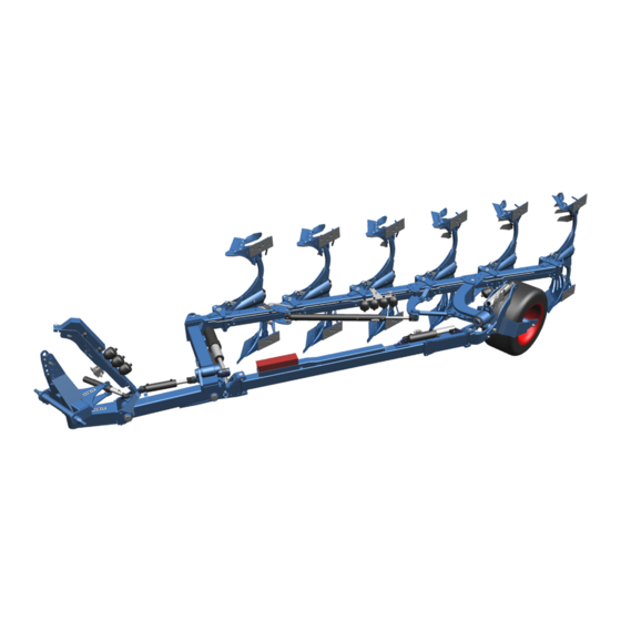
- Page 1 OPERATING INSTRUCTIONS SEMI-MOUNTED REVERSIBLE PLOUGH DIAMANT 16 / 16 U / 16 V / 16 VU en-GB | Item no. 17514534 | BA 00/06.2020...
- Page 2 Pass these instructions to all users / owners. Original instructions © 2020 | This documentation is copyright protected. The copyright remains with LEMKEN GmbH & Co. KG, Weseler Strasse 5, D-46519 Alpen. The texts, diagrams and drawings must not be duplicated, distributed or disclosed in any other way,...
-
Page 3: Table Of Contents
Table of contents Table of contents About these instructions............................1 1.1 Introduction................................. 1 1.2 Target groups..............................2 1.3 Applied symbols..............................2 1.3.1 Design of warning signs..........................2 1.3.2 Signal words and hazard statements...................... 3 1.3.3 Warning of property damage........................3 1.3.4 Other notices and information........................ - Page 4 Table of contents 3.14 Plough body..............................25 3.15 Additional tools............................. 25 3.16 Disc coulter..............................26 3.17 Subsoiler................................28 Attachment................................29 4.1 Checking suitability of the tractor......................29 4.2 Preparing the tractor............................30 4.3 Preparing the implement..........................31 4.4 Attaching the implement..........................31 Road travel.................................
- Page 5 Table of contents 6.3.12 Adjusting the working depth of the subsoilers................61 6.3.13 Adjusting the trashboard ........................61 6.3.14 Adjusting the skimmer ........................... 63 6.3.15 Adjusting the disc coulter........................66 6.3.16 Adjusting the hydraulic overload safety device................69 6.4 Working with the implement........................72 6.4.1 Standard procedure............................
- Page 6 Table of contents Technical data................................90 12.1 Dimensions..............................90 12.2 Machine weights............................91 12.3 Permissible weights............................. 92 12.4 Required drawbar load..........................92 12.5 Performance data............................92 12.6 Connection data............................93 12.6.1 Electrical connections..........................93 12.6.2 Hydraulic connections..........................94 12.7 Noise, airborne sound..........................94 12.8 Operating materials.............................
-
Page 7: About These Instructions
About these instructions About these instructions Introduction Observe the operating instructions These operating instructions are important and belong to the imple‐ ment's scope of delivery. These operating instructions must be available to the user at the place of use. Always read chapter "Safety" before using the implement for the first time. -
Page 8: Target Groups
About these instructions Initial commissioning These operating instructions do not describe initial commissioning. INFORMATION Prior to operation, initial commissioning and instruction in operation, setting and maintenance must have been carried out by the dealer. Target groups The target groups of these operating instructions are operators, users and service personnel of the implement. -
Page 9: Signal Words And Hazard Statements
About these instructions 1.3.2 Signal words and hazard statements The following signal words and hazard statements are used to label warning signs and to warn of residual risks: DANGER Indicates an immediate hazardous situation If the hazardous situation is not avoided, it will result in death or serious injury. -
Page 10: Symbols And Text Markings
About these instructions 1.3.5 Symbols and text markings Symbol, text marking Meaning In front of and in texts Marking for routine maintenance ● tasks Activities that demand the help of service staff. Listing Position numbers [1], Example: ‘Settings’ Software element Example: [OK] Softkey, key, switch and button [kg]... -
Page 11: Further Applicable Documents
About these instructions Further applicable documents Further documents to be observed: Operating instructions of the tractor For partially assembled or disassembled delivery: Mounting instructions Spare-parts list en-GB | Item no. 17514534 | BA 00/06.2020... -
Page 12: Safety
Safety Safety Intended use The implement is used for soil cultivation on agricultural land. It may only be used in accordance with the recognised rules of good agricultural practice. Limitations The permitted working depth is limited to the cultivatable soil horizons. Not intended for use in the following cases: On very or deep-frozen soils In soil horizons with unweathered bedrock... -
Page 13: Personnel Qualification Requirements
Safety Technically perfect condition Operate the implement only in a technically perfect condition. ► Observe the maintenance instructions. Perform all the necessary ► tests. Use original spare parts or parts approved by the manufacturer. ► Only use the auxiliary and operating materials listed. ►... -
Page 14: Hazardous Areas
Safety Service personnel Service personnel within the meaning of these instructions are all persons who maintain and repair safety-relevant components. Service personnel are qualified for these activities based on their training and expertise (for example agricultural machine mechanics). Hazardous areas If the hazardous areas are not heeded, this may result in death or serious injury to personnel. - Page 15 Safety Hazardous area between tractor and When standing between the tractor and the implement there is a risk implement due to tractor movements or sudden implement movements. Secure the tractor to prevent it from rolling away. ► Before operating the linkage: Keep all persons away from the ►...
-
Page 16: Workplaces And Passengers
Safety Workplaces and passengers Workplaces The main workplace for working with the implement is the driver’s seat in the tractor. Further workplaces are described in the respective instructions for action. Dangerous situations may occur if several persons operate the imple‐ ment functions at the same time. - Page 17 Safety Danger due to damage to the imple‐ Damage to the implement can impair the operational safety of the ment implement and cause accidents. This may lead to serious personal injury or death. To ensure that the implement is in a safe condition, carry out the following measures: Check the implement according to the maintenance schedule.
-
Page 18: Safe Handling
Safety Safe handling 2.6.1 Personal protective equipment Carrying and wearing protective equipment is an important safety component. Lack of or inappropriate protective equipment increases the risk of damage to health and injury to persons. For certain work on the implement, the following protective equipment is required in addition to suitable workwear: Safety gloves Use protective equipment as follows:... -
Page 19: Safety Devices And Labels
Safety Safety devices and labels For the protection of the user, other persons and the implement, the implement is equipped with special safety devices, e.g.: The actual equipment of the implement with safety devices depends on the country-specific rules and regulations. Ä The available safety devices are described in chapter Safety devices on page 18. -
Page 20: Design And Description
Design and description Design and description Implement overview INFORMATION Depending on the equipment of the implement and country-specific requirements, the assembly groups described below may be present on the implement. Headstock Stabiliser OptiLine adjustment system for traction line correc‐ Transport wheel tion Plough bodies Hydraulic ram for the traction increase device... -
Page 21: Implement Safety
Design and description Implement safety 3.2.1 Position of the labels Overview of safety symbols, warning stickers and other symbols 3.2.2 Meaning of the labels This section explains the information and warning signs that have been affixed to the implement. Read the operating instructions Incorrect use or operation of the implement can result in death or serious injury. - Page 22 Design and description Turn off the engine A tractor with the engine running can cause unintentional movements. This may even be fatal or result in serious injuries. Before maintenance and repair work: Turn off the engine. ► Engage the parking brake of the tractor. ►...
- Page 23 P0/T0 - hydraulic overload safety device Hydromatic - comfort version P1/T1 - turnover device (OF-reverse rotation) P2/T2 - hydraulic working width adjustment (only Diamant 16 V / 16 VT) P3/T3/T* - depending on the equipment: *Only for machines with an OptiLine adjustment system...
-
Page 24: Safety Devices
Design and description Depth adjustment Mechanical adjustment of the working depth Positioning points for jack Positioning points for jack 3.2.3 Safety devices 3.2.3.1 Lighting equipment and identification The identification and the lighting equipment increase safety while driving on the road. For public road traffic, the implement must be equipped with the following components in accordance with national regulations: Labelling... - Page 25 Design and description Lighting equipment Example of rear lighting equipment Warning boards Lateral reflectors LED lighting equipment Rear reflectors Warning board Depending on national regulations, a warning board may be required for slow-moving vehicles. 3.2.3.2 Stabilisation Stand The stand ensures that the dismantled machine is stable. When mounted, the stand is folded up again.
-
Page 26: Type Plate
Design and description 3.2.3.3 Protection against unauthorised use The protection against unauthorised use ensures that only authorised person can attach the implement to a tractor. The following versions are available: Protection against unauthorised use for cross shafts Type plate The implement is marked with a type plate. The implement type is uniquely defined on the type plate. -
Page 27: Headstock
Design and description Ä Further type plate variants: Type plate variants on page 102. Headstock Headstock The headstock with cross shaft and top link pin has been Cross shaft designed according to standard ISO 730. Top link pin The headstock is used to connect the implement to the three-point linkage of the tractor. -
Page 28: Working Width Adjustment
Design and description Working width adjustment Depending on the equipment, the user can adjust the working width mechanically or hydraulically. Mechanical – fourfold Hydraulic – infinitely Turnover device Turnover device The machine is equipped with a hydraulic turnover device which Turnover ram turns the plough frame via two turnover rams Frame swing-in... -
Page 29: Wheels
Design and description Wheels Transport wheel The transport wheel minimises the ground pressure when ploughing and ensures safe road transport. Support wheel The on-land version of the support wheel is mounted on the frame and prevents the plough from working too deeply. During the turning process, the support wheel swivels into the position corresponding to the respective operating position. -
Page 30: Traction Line Correction With The Optiline Adjustment System
Design and description Double-cutting shearing protection Shear bolt Double-cutting shearing protection in the leg brackets is standard on all implements. Shear bolts are replaced when broken. Hydraulic overload safety device Hydraulic overload safety device With the hydraulic overload safety device the release force is adjusted between a minimum and a maximum release pressure. -
Page 31: Plough Body
Design and description 3.14 Plough body DuraMaxx Slat The slats or mouldboards are attached to the frog with hooks Mouldboards . As such the wearing parts can be exchanged rapidly without tools. Hook Frog Frog Dural Mouldboard blade The following belongs to the plough body: Shin Mouldboard, divided into shin and mouldboard blade... -
Page 32: Disc Coulter
Design and description Trashboard Trashboard Skimmers Skimmers Sword coulter 3.16 Disc coulter The large disc coulters ensure a clean furrow. Examples: en-GB | Item no. 17514534 | BA 00/06.2020... - Page 33 Design and description Disc coulter, smooth Equipment with disc coulter smooth, stalk rigid Stalk, rigid Disc coulter, smooth Equipment with disc coulter toothed, stalk spring-loaded Stalk, spring-loaded Disc coulter, smooth Equipment with disc coulter smooth, stalk rigid, adjustable Stalk rigid, adjustable lengthwise lengthwise en-GB | Item no.
-
Page 34: Subsoiler
Design and description 3.17 Subsoiler Example: Subsoiler en-GB | Item no. 17514534 | BA 00/06.2020... -
Page 35: Attachment
Attachment Attachment Checking suitability of the tractor WARNING Risk of accident due to unsuitable tractor If the tractor is not suitable for the implement, compo‐ nents of the implement may be overloaded and the tractor implement combination may not be steered safely. -
Page 36: Preparing The Tractor
Attachment Preparing the tractor Keep the tractor documentation The tractor is prepared before mounting the implement. For this pur‐ ready pose, the user must carry out various checks and adjustments. The following information about the tractor is required: Air pressure of tyres Instructions for adjusting the lifting rods Instructions for adjusting the check chains or stabilisers WARNING... -
Page 37: Preparing The Implement
Attachment Preparing the implement Headstock attachment position The headstock has 2 attachment positions: Cross shaft towards the rear (standard position) Cross shaft towards the front Swivelling the headstock increases or decreases the distance between the plough’s pivot point and the tractor’s rear axle. Select the small distance to minimise side pull. - Page 38 Attachment Preconditions: √ The tractor is suitable for operating the implement Ä page 29. √ The tractor is prepared Ä page 30. √ The implement is prepared Attachment 1. Where possible: Align the cross shaft horizontally to the ground by moving the headstock 2.
- Page 39 Attachment 11. Fold in the stand 12. With the lower links of the tractor and at the trailer: Align the lower edge of the stabiliser parallel to the ground. Keep a 400 mm distance to the ground. Stand After attachment After attachment to the tractor: 1.
- Page 40 Attachment 5. Machine with traction increase device: Open the shut-off valve Check the operating pressure and adjust, if necessary. Ä Chapter 6.3.2 ‘Adjusting the operating pressure for the traction increase device’ on page 47 Shut-off valve open en-GB | Item no. 17514534 | BA 00/06.2020...
-
Page 41: Road Travel
Road travel Road travel Information on road travel Laws on driving on public roads differ in many countries. Pay particular attention to local laws and regulations regarding the ► following points: Driving on public highways Lighting equipment of mounted implements Identification of mounted implements NEVER exceed the maximum transport speed of the implement. -
Page 42: Adjusting The Suspension
Road travel 5.2.1 Adjusting the suspension 1. Make sure that the shut-off valve of the traction increase device is open. ð During road travel, impacts and overloads are avoided. 2. Open the shut-off valve of the shock absorber. ð Shock absorption is activated. Shut-off valve shock absorber 3. -
Page 43: Preparing The Lighting Equipment For Road Travel
Road travel 5.2.2 Preparing the lighting equipment for road travel Mounting the lighting equipment The lighting equipment is mounted in transport position. 1. Lift out the implement. 2. Turn the implement to the transport position. Ä Chapter 6.1.3 ‘Moving the plough from operating position to trans‐ port position’... -
Page 44: Subsoilers
Road travel 5.2.3 Subsoilers Before driving on the road: Move the subsoilers to the transport posi‐ tion. DuraMaxx (left) and Dural (right) Subsoiler 1. Release the locking bar (DuraMaxx) or pin (Dural) Holder 2. Pull the subsoiler Locking bar out of the holder 3. -
Page 45: Operation
Operation Operation Basic operation 6.1.1 Operate the stand Fold the stand 1. Unlock the stand Dismantle the pin 2. Swivel the stand to the desired position. 3. Secure the stand. Insert the pins in the holes Secure the pin with the linch pin. Stand Pin for folding Hole... - Page 46 Operation 1. Set the control unit for the semi-mounted wheel to "P". 2. Hold the control unit until the system pressure drops to 0 bar. ð Indicator at the pressure gauge is at 0 bar. The plough is lifted. 3. In order to apply pressure to the bottom turnover ram with the control unit: Switch the control unit to the first pressure position.
-
Page 47: Moving The Plough From Operating Position To Transport Position
Operation 6.1.3 Moving the plough from operating position to transport position 1. Use the additional control unit of the semi-mounted wheel to lift the implement completely out of the ground. 2. Lift the three-point power lift of the tractor. 3. Turn the plough to the half-rotated position = centre position. 4. -
Page 48: Operating The On-Land Version
Operation 4. Machine with frame swing-in: Dismantle the pin of the frame swing-in. Close the shut-off valves at the turnover ram. Open the shut-off valve at the hydraulic ram of the frame swing-in. With the additional control unit of the turnover device: Swing out the frame swing-in. - Page 49 Operation 6. Insert the pin into the intended hole. 7. Secure the pin with the linch pin. 8. Close the shut-off valves of the hydraulic ram 9. Open the shut-off valves of the turnover rams 10. Turn the frame to the centre position. Shut-off valves 11.
-
Page 50: Changing The Setup State
Operation 9. Open the shut-off valves of both turnover rams Free hole 10. Turn the frame to the centre position. Shut-off valve Turnover ram ð The support wheel swivels to the centre position. Stop 11. Remove the pin Turning link 12. -
Page 51: Mounting The Wide Furrow Cutter
Operation 6.2.3 Mounting the wide furrow cutter Wide furrow cutter The wide furrow cutter widens the furrow of the last plough body. √ Application: light to medium soils ► Mount the wide furrow cutter at the last plough body. 6.2.4 Mounting the attachment arm √... - Page 52 Operation Adjustment options on the machine Adjustment Operating pressure traction increase device Ä Adjusting the operating pressure for the traction increase device, page 47 Working depth Ä Adjusting the working depth897f 48 Inclination Ä Adjusting the inclination, page 51 Adaptation of the front furrow width to the working Ä...
-
Page 53: Adjusting The Operating Pressure For The Traction Increase Device
Operation 6.3.2 Adjusting the operating pressure for the traction increase device Check the operating pressure Precondition: √ Implement is mounted on the tractor. √ The hydraulic hoses are connected to the tractor. √ The shut-off valve is open 1. Turn the plough to the operating position. 2. -
Page 54: Adjusting The Working Depth
Operation Change the operating pressure 1. Set the additional control unit for the semi-mounted wheel to "T". ð The plough is lowered. 2. Draw the plough into the ground. ð The current operating pressure is shown on the pressure gauge 3. - Page 55 Operation Mechanical depth adjustment Pin adjustments‑ are available for the mechanical depth adjustment. 1. To relieve the pin of the pin adjustment: Extend the hydraulic ram of the trailer slightly. 2. Remove the pin. Pin adjustment 3. Re-position the pin in the holes of the pin adjustment Hydraulic ram Hole 1 = lowest working depth...
- Page 56 Operation Hydraulic depth adjustment 1. Lower the plough to the working depth currently set. 2. Set the valve on the trailer to "SET". Manual-hydraulic depth adjustment: Via the shut-off valve Electro-hydraulic depth adjustment: Via the electrovalve with the control 3. Adjusting the working depth: Lift and lower the transport wheel via the additional tractor control unit.
-
Page 57: Adjusting The Inclination
Operation Furrow operation In furrow operation, the support wheel is swivelled into the centre position and locked with the stop. 1. Turn the frame to the centre position. ð The support wheel swivels to the centre position. 2. Remove the pin 3. -
Page 58: Adjusting The Distance Of The Tractor To The Furrow Edge - On-Land Version
Operation Manual adjustment with turnbuckle Check the front furrow width: ► Front furrow width Adjustment Too wide Turn the turnbuckle shorter. Too narrow Turn the turnbuckle longer. Hydraulic adjustment with hydraulic Check the front furrow width: ► Front furrow width Adjustment Too wide Retract hydraulic ram. - Page 59 Operation Manual adjustment with turnbuckle Check the front furrow width: ► Front furrow width Adjustment Too wide Turn the turnbuckle longer. Too narrow Turn the turnbuckle shorter. Hydraulic adjustment with hydraulic Check the front furrow width: ► Front furrow width Adjustment Too wide Extend hydraulic ram.
-
Page 60: Adjusting The Tractor/Plough Traction Line
Operation 6.3.7 Adjusting the tractor/plough traction line Adjusting the traction line with the OptiLine adjustment system The machine is optimally adjusted when... Middle rear tractor axle Plough centre ... the tractor/plough traction line (connection line between the Draw point draw point and the centre of the plough ) runs through the middle of the rear tractor axle... -
Page 61: Adjusting The Draw Point Height (On-Land Version)
Operation 6.3.8 Adjusting the draw point height (on-land version) When using the machine with crawler tractors with only one set of tracks on each side: 1. Make sure while working that the trailer applies the same ground pressure over the entire length. 2. - Page 62 Operation Changing pitch angle: 1. Undo the nut The eccentric plate can be rotated. Eccentric plate 2. Undo the nut The plough body can be swivelled around this pivot point. Target Pitch Adjustment angle Improved Larger Notch on the eccentric plate penetration pitch downwards...
-
Page 63: Adjusting The Working Width Of The Plough Bodies
Operation The pitch angle is adjusted via the two adjusting screws , . When delivered, the plough bodies are mounted at an average pitch angle to the ground. Changing pitch angle: 1. Undo the screw 2. Undo the self-locking nut of the bolted connection The plough body can be swivelled around this pivot point. - Page 64 Operation Screw Working width per body Interbody clear‐ Screw ance [cm] Hole B1 Hole B2 Hole B3 Hole B4 Bracket The working width is adjusted by adjusting the individual plough bodies. The leg brackets of the individual plough bodies have holes for 4 different positions.
- Page 65 Operation The working width of the plough bodies is adjusted via the tractor. The hydraulic ram for adjusting the working width is controlled via an additional tractor control unit. Preconditions: √ The front furrow width is adjusted. √ The tractor/plough traction line is adjusted. Adjust the working width.
-
Page 66: Landside
Operation 6.3.11 Landside Only possible with DuraMaxx plough bodies Landside Screw To optimise guidance on slopes, move the landside V1 to a lower Screw position. INFORMATION Set the landsides on all the plough bodies to the same position. 1. Undo the screw 2. -
Page 67: Adjusting The Working Depth Of The Subsoilers
Operation 6.3.12 Adjusting the working depth of the subsoilers DuraMaxx (left) and Dural (right) Subsoiler 1. Slide the subsoiler into the holder from below. Holder 2. Secure the subsoiler with a locking bar (DuraMaxx) Locking bar or pin (Dural) 3. To change between the two positions: Release the locking bar or the pin Move the subsoiler... - Page 68 Operation DuraMaxx equipment Trashboard 1. Align the trashboard using the slots on the holder Holder 2. Screw the trashboard to the holder. 3. Align the holder using the slots on the leg Slots 4. Screw the holder to the leg. Slots Slots Slots...
-
Page 69: Adjusting The Skimmer
Operation Support screw Lock nut 6.3.14 Adjusting the skimmer The skimmer has the following setup options: Working depth Stalk position Projection angle Working depth Target: Distance The required working depth of the skimmer is approx. 5 to 10 cm. – For a plough working depth of 25 cm, this results in a distance (skimmer point to plough body point) of approx. - Page 70 Operation CAUTION Risk of crushing The skimmer may fall down when removing the pin. – Hold the skimmer with one hand until the skimmer has been secured to the stalk again with the pin. 1. Unlock the pin 2. Pull out the pin. 3.
- Page 71 Operation Projection angle In the standard version, the projection angle of the skimmer cannot be Swivelling bracket changed. Bracket Position a Side distance: Position b In conjunction with the projection angle setting, three different posi‐ Position c tions for installing the swivelling bracket on the bracket can be selected.
-
Page 72: Adjusting The Disc Coulter
Operation 6.3.15 Adjusting the disc coulter The disc coulters have been adjusted for operation at the factory. Sub‐ Retaining ring sequent adjustments for the disc coulters are only necessary when the setup state is changed. The disc coulters offer the following adjustment options: Working depth Side distance Swivel limit... - Page 73 Operation Rigid disc coulter: 1. Undo the screw 2. Swivel the coulter arm to the required working depth. 3. Retighten the screw Coulter arm Screw Side distance Side distance Targets: Working depth Disc coulters cut 2 cm to 3 cm wider than the trailing tools. Disc coulters run parallel to the landside of the plough body.
- Page 74 Operation 3. Retighten the screw . Ä Tightening torques, page 103 Swivel limit Targets: Disc coulters run parallel to the landside of the plough body. Side distance to the landside of the plough body: approx. 2 to 3 cm (when swivelled) Disc coulters must not collide with the skimmers when swivelling them in.
-
Page 75: Adjusting The Hydraulic Overload Safety Device
Operation Disc coulter without skimmer equipment ► Adjust the adjusting piece to ensure the swivelled in disc coulter is facing the point of the plough body. Disc coulter 6.3.16 Adjusting the hydraulic overload safety device Adjusting piece Point of the plough body Operating pressure With the operating pressure, the user can set when a plough body will move upwards or to the side to avoid an obstacle. - Page 76 Operation Adjusting the standard version During work, the user can set any desired pressure at the machine between the minimum operating pressure (³ 125 bar) and the max‐ imum operating pressure (£ 200 bar). Change the operating pressure 1. At the driver’s seat, switch the additional control unit for the trans‐ port wheel: "P"...
- Page 77 Operation 4. Set the desired minimum operating pressure. Increase the minimum oper‐ Turn the rotary knob ating pressure: clockwise. Reduce the minimum oper‐ Turn the rotary knob ating pressure: anticlockwise. 5. Switch the additional control unit to the "T" position for a few seconds.
-
Page 78: Working With The Implement
Operation Working with the implement 6.4.1 Standard procedure 1. Bring the tractor implement combination into position. 2. Dismantle the lighting equipment. 3. Adjust the implement. 4. Close the shut-off valve of the shock absorber. ð Shock absorption is disabled. 5. At an implement with a hydraulic overload safety device: Switch the tractor control unit to the float position. -
Page 79: Driving On The Headland
Operation 6.4.2 Driving on the headland 1. Before the headland: Lift the three-point power lift of the tractor. Use the additional control unit of the transport wheel to lift the machine completely out of the ground. Turn the machine to the centre position. ATTENTION: If parts of the machine come into contact with the ground, the machine components may be damaged when turning. -
Page 80: Cleaning And Care
Cleaning and care Cleaning and care After working in the field Remove soil from the implement. ► ð No soiling of roads: Soil remains in the field. Cleaning with high-pressure cleaner The user can clean the implement with the high-pressure cleaner. When cleaning, the user must observe the following: ATTENTION Damage due to cleaning with a high-pressure cleaner... -
Page 81: Detaching
Detaching Detaching Removing the machine Preconditions: √ Parking space: Solid, level floor that offers sufficient carrying capacity √ Subsoilers are in the transport position. √ Prior to extended breaks or winter storage: Clean and lubricate the machine. 1. Out of operation: Remove the screw for right-turning angular adjustment. - Page 82 Detaching 5. Machine with traction increase device: Close the shut-off valve of the traction increase device. ð The pressure supply to the hydraulic ram is interrupted. 6. Lower the machine. 7. Unlock the pins on the stands. To do so, remove the linch pins. Keep hold of the stands with one hand.
-
Page 83: Maintenance And Repair Work
Maintenance and repair work Maintenance and repair work Maintaining the implement properly Personnel Service personnel are required for certain activities, e.g. working on hydraulic hoses. These activities are indicated in the maintenance schedule by the symbol 9.1.1 Preparations 1. Switch off the implement. 2. -
Page 84: Maintenance
Maintenance and repair work Maintenance 9.2.1 Maintenance schedule Chap. Task to execute Check the top link pin Check tyres Check air pressure Check wheel nuts Checking hydraulic hoses Replacing hydraulic hoses Check hydraulic connections Checking connector plugs and lines Check soil cultivation implements en-GB | Item no. -
Page 85: Tractor Connection
Maintenance and repair work 9.2.2 Tractor connection Check the top link pin 1. Visual inspection of the top link pin for: Damage Wear 2. Replace damaged or worn top link pins. 9.2.3 Frame 9.2.3.1 Tyres and wheels Check tyres Visual inspection ►... -
Page 86: Hydraulics
Maintenance and repair work Check wheel nuts Tighten the wheel nuts on the implement to the respective tight‐ ► ening torque. 9.2.4 Hydraulics Checking hydraulic hoses 1. Check hydraulic hoses for damage and leakages. ð Replace damaged or defective hydraulic hoses immedi‐ ately. -
Page 87: Electrics
Maintenance and repair work 9.2.5 Electrics Checking connector plugs and lines Perform visual inspection of the connector plugs and cables. ► Watch for bent or broken contact pins in the plugs. Watch for exposed places in cables. ð Repair damaged connector plugs or cable connections immediately or have them replaced. -
Page 88: Lubricating Components Via Grease Nipples
Maintenance and repair work Chap. Task to execute OptiLine adjustment system Grease pin Grease piston rods Grease surfaces *Lubricating points have varying intervals. 9.3.2 Lubricating components via grease nipples Turnover device bearing and stabil‐ iser bearing* *Lubricating points have varying intervals. 1. - Page 89 Maintenance and repair work Headstock bearing* *Lubricating points have varying intervals. 1. Lubricate grease nipples every 10 operating hours. 2. Lubricate grease nipples every 100 operating hours. 3. Lubricate all lubricating points before the season and after cleaning. Turnbuckle 1. Lubricate grease nipples before the season and after cleaning. 2.
-
Page 90: Greasing Components
Maintenance and repair work Swivel brackets and control rod (Dia‐ mant V) 1. Lubricate grease nipples every 50 operating hours. 2. Lubricate all lubricating points before the season and after cleaning. Traction increase device 1. Lubricate grease nipples every 10 operating hours. 2. -
Page 91: 10 Troubleshooting And Error Correction
Troubleshooting and error correction 10 Troubleshooting and error correction 10.1 Find and eliminate errors correctly 10.1.1 Prior to troubleshooting at the implement 1. Park the tractor-device combination. 2. Secure the tractor-device combination to prevent it from rolling away. 3. When working on the folding implement: Fold out the folding parts of the implements or secure them against folding out. -
Page 92: Error - Cause - Remedies At A Glance
Troubleshooting and error correction 10.2 Error - Cause - Remedies at a glance Penetration and depth control of the plough, slippage Fault description Cause Remedy Plough fails to remain in Penetration force is too low. Penetrate soil with body: Reduce the distance of the soil. -
Page 93: Replacing The Shear Bolt
Troubleshooting and error correction 10.3 Replacing the shear bolt All the implements are equipped with shearing protection. WARNING Risk of impact Plough bodies release upwards when the shear bolt is overloaded. Sudden swinging back of the body can lead to serious personal injury. –... - Page 94 Troubleshooting and error correction 8. Swivel the plough body all the way back into the operating posi‐ tion by hand. WARNING: Risk of crushing due to moving components Keep hands and fingers away from the area of the stalk and the leg bracket.
-
Page 95: Shutdown And Disposal
Shutdown and disposal 11 Shutdown and disposal 11.1 Shutdown When the implement can no longer be used, it is dismantled and broken down into its components. Special knowledge is required to dismantle the implement. CAUTION Risk of accidents due to discharge of stored energy Springs are under tension. -
Page 96: Technical Data
£ 2300 Approx. transport width [mm] £ 4000 Approx. transport height [mm] Working width of each plough body - Diamant 16 / 16 U 400/450/530/600 [mm] Working width of each plough body - Diamant 16 V / 16 300 – 600... -
Page 97: Machine Weights
5700 5800 Gross weight, min. [kg] 2400 2800 3200 3600 4000 For determining the actual weights: Weigh Diamant 16 U / 16 VU Drawbar load, max. [kg] 3500 3500 3500 3500 Drawbar load, min. [kg] 1110 1140 Axle load, max. [kg]... -
Page 98: Permissible Weights
Technical data 12.3 Permissible weights Do not exceed the loads and weights. Observe national regulations and laws. Diamant 16 / 16 U / 16 V / 16 VU Drawbar load [kg] 3500 Axle load [kg] 3500 Gross weight [kg] 7000 12.4... -
Page 99: Connection Data
Technical data 12.6 Connection data 12.6.1 Electrical connections Voltage sources Consumer Voltage Direct connection Power socket [Volt] to the tractor battery Lighting equipment According to DIN ISO 1724 Lighting equipment According to ISO 1185 (Canada, USA) Voltage tolerance range: 10 V to 15 V en-GB | Item no. -
Page 100: Hydraulic Connections
Technical data 12.6.2 Hydraulic connections Hydraulic connections and control units Consumer Colour Code Hydraulic overload safety device - com‐ White P0 / T0 ● fort version Turnover device (OF version) P1 / T1 ● Hydraulic working width adjustment Green P2 / T2 ●... -
Page 101: Operating Materials
High performance lubrication grease with MoS solid lubricants (e.g. Castrol Molub-Alloy 370-2) Turnover device: Olystamoy 2 12.9 Tyres and wheels Diamant 16 / 16 U / 16 V / 16 VU Tyre size Manufac‐ Profile Ply rating Load + Air pressure... -
Page 102: 12.10 Connecting Equipment At The Implement
Technical data 12.10 Connecting equipment at the implement Permitted categories for cross shafts and top link pins Diamant 16 / 16 U / 16 V / 16 VU Cross shaft category 3N Cross shaft category 3 Cross shaft category 3 (CAT 4 ball, L3, Z3–91 Cross shaft category 4N Top link pin –... -
Page 103: Index
Index Index Disc coulter ......26 Adjust ......66 Additional tools . - Page 104 Index Maintain ......80 Replacing hoses ..... . . 80 Machine Remove .
- Page 105 Index Stabilisation ......19 lubrication ......84 Safety equipment Piston rods Protection against unauthorised use .
- Page 106 Index Traction line correction ....24 Working depth Tractor Adjust ......48 Check suitability .
-
Page 107: Appendix
Appendix Appendix en-GB | Item no. 17514534 | BA 00/06.2020... -
Page 108: A Type Plate Variants
Type plate variants Type plate variants Series 10 Permissible axle load [kg] (axle 1) Type designation 11 Permissible axle load [kg] (axle 2) Serial number 12 CE label Year of manufacture 13 EAC label Vehicle class, subclass, speed index 14 Company name and address of the manufacturer EU type approval number 14a Address of the manufacturer Vehicle identification number. -
Page 109: B Tightening Torques
Tightening torques Tightening torques General information about bolted connections 1. Identify screw connections. Check identification marking on the screw and nut if necessary. Check the description in the spare-parts list. 2. Secure screw connections with once loosened self-locking nuts against self-loosening. Use one of the following measures: Use new self-locking nuts. - Page 110 Tightening torques Screws and nuts made of V2A Diameter Tightening torque [Nm] 1.37 Wheel bolts and wheel nuts Diameter Tightening torque [Nm] M18x1.5 M20x1.5 M22x1.5 en-GB | Item no. 17514534 | BA 00/06.2020...
-
Page 111: C Cross Shaft Overview
Cross shaft overview Cross shaft overview To determine the cross shaft or lower link connection: Determine the dimensions shown in the sketch on the implement. Compare the dimensions with the data in the table. The category of the three-point linkage must match with the cate‐ gory of cross shaft or lower link connection. - Page 113 LEMKEN GmbH & Co. KG Weseler Strasse 5 D-46519 Alpen Telephone: +49 2802 81-0 Fax: +49 2802 81-220 Email: info@lemken.com Internet: www.lemken.com...
Need help?
Do you have a question about the DIAMANT 16 and is the answer not in the manual?
Questions and answers