Table of Contents
Advertisement
Operating
Instructions
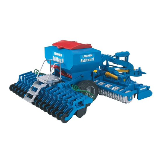
Seed Drills
Solitair 9,
Solitair 9 K,
Solitair 9 KA
SAFETY IS OUR CONCERN!
Art.-Nr.: 175 3683
GB-1/11.02
LEMKEN GmbH & Co. KG
Weseler Straße 5, D-46519 Alpen / Postfach 11 60, D-46515 Alpen
Telefon (0 28 02) 81-0, Telefax (0 28 02) 81-220
E-Mail: lemken@lemken.com, Internet: http://www.lemken.com
Advertisement
Table of Contents

Related Manuals for LEMKEN Solitair 9


Summary of Contents for LEMKEN Solitair 9
- Page 1 Solitair 9 KA SAFETY IS OUR CONCERN! Art.-Nr.: 175 3683 GB-1/11.02 LEMKEN GmbH & Co. KG Weseler Straße 5, D-46519 Alpen / Postfach 11 60, D-46515 Alpen Telefon (0 28 02) 81-0, Telefax (0 28 02) 81-220 E-Mail: lemken@lemken.com, Internet: http://www.lemken.com...
- Page 3 Only use genuine Lemken spare-parts. Spurious parts negatively influence the function of the implement, show a shorter lifetime and increase in nearly all cases additional maintenance. We trust that you will understand that LEMKEN is unable to guarantee poor operation and damage caused by using spurious parts!
-
Page 5: Table Of Contents
„General Health- and Safety pre- cautions“! • The LEMKEN Solitair 9 has been designed purely for the agricultural use! • Any use beyond the one stipulated above is no longer considered as defi- ned use! •... - Page 6 6.1.1 Attaching to the three point linkage ........23 6.1.2 Detaching from the three point linkage ......24 Mounting and Dismounting............. 25 6.2.1 Mounting on a mounted LEMKEN soil cultivation implement 6.2.2 Dismounting from a mounted LEMKEN soil cultivation imple- ment ..................27 6.2.3 Mounting on a semi-mounted LEMKEN soil cultivation imple-...
- Page 7 Height adjustment of the coulter bar frame ......40 Drilling depth................40 10 ADJUSTMENTS / OPERATION ............41 10.1 Seeding shafts ................. 41 10.2 Seed table ................. 43 10.3 Slide plates ................44 10.4 Bottom flaps ................44 10.5 Emptying the hopper ............... 44 10.5.1Emptying flaps ..............
- Page 8 21.1 Single harrows................58 21.2 S-harrow..................58 21.3 Hydraulic harrow lifting device ..........59 22 PRE-EMERGENCE MARKERS ............60 22.1 General Instructions ..............60 22.2 Pre-emergence markers - hydraulic, double acting....60 22.3 Pre-emergence markers - hydraulic, single acting ....61 22.4 Depth of the marking groove ..........
- Page 9 32.9 End stop..................72 33 NOISE, AIRBORNE SOUND ............. 73 34 NOTES ....................73 35 PRODUCT REGISTRATION / GUARANTEE ........73 INDEX ....................... 75 EC CERTIFICATE OF CONFORMITY ..........79...
-
Page 10: Safety Instructions
SAFETY INSTRUCTIONS General Safety Instructions • Before using the machine, always check both it and the tractor for roadworthiness and operational safety! • As well as the notes in these instructions the operator is ad- vised to comply with the generally applicable safety at work regulations and those relating to use of the public highway! •... - Page 11 • Never leave the driver's seat whilst in motion! • Handling behaviour, steerability and braking are influenced by mounted implements, trailers and ballast weights. Check for sufficient steerability and braking! • When driving round bends note the width of the machine and/or changing centre of gravity of the implement.
- Page 12 • Regularly check the hydraulic pipes and replace them in the event of dam- age or signs of ageing. The replacement pipes must comply with the tech- nical specification as laid down by Lemken! • When searching for leaks appropriate equipment should be used because of the danger of injury! •...
- Page 13 Tyres • When working on the tyres make sure that the implement has been placed on the ground safely and that it is secured by chocks against unintentional rolling! • Fitting tyres requires knowledge and special tools! • Repairwork on tyres may only be conducted by trained staff and with suit- able tools! •...
-
Page 14: Warning Stickers
WARNING STICKERS 2.1 General Instructions The LEMKEN Solitair 9 is equipped with all features to ensure safe operation. Where potential danger areas of the implement can not be fully safeguarded, warning stickers are fitted which draw attention to these. Damaged, lost or un- readable warning stickers must be replaced immediately. - Page 15 WARNING!Do not ride with on the platform of the imple- ment! WARNING! Pinch Points! WARNING! Danger due to moving parts! WARNING! Keep well clear of the folding area of the implement! WARNING! Keep well clear of the working and swinging area of the imple- ment!
-
Page 16: Positions Of The Warning Stickers
Positions of the warning stickers... -
Page 17: Preparation Of Tractor
PREPARATION OF TRACTOR Tyres Ensure that all are at the manufacturer's recommended pressures and that left and right hand side tyre pressures are identical. (See Manufacturer's In- structions)! Lift Rods Adjust lift rods to equal length by means of the adjuster device ! Check chains or sway blocks It is essential that the check chains or sway blocks are adjusted so that the lower links are fixed sideways when in working position. -
Page 18: Calculation Of The Minimum Front Ballast Gv Min
How to calculate the minimum front ballast and the increasing of the rear axle load, is described in detail as follows: = Weight of front ballast (front implement) = Front axle load of the tractor without mounted implement = Tractor dead weight = Rear axle load of the tractor without mounted implement = Weight of the implement combination 3.5.1 Calculation of the minimum front ballast G... -
Page 19: Required Spool Valves / Hose Marking
Required spool valves / Hose marking For the hydraulic devices of the Solitair 9 the following spool valves must be available: sing acting double acting colour code spool valves spool valves with pressure = pressureless yellow Hydraulic motor for fan... -
Page 20: Required Sockets
Required sockets For the electric devices of the Solitair 9 the following power sources must be available with the tractor. Function Voltage Direct connection Socket to the battery On-board computer LH 5000 / seed drill con- trol Lighting equipment according to... -
Page 21: First Use
FIRST USE Before the first use of the Solitair, the following items must be checked: • Disc coulter and pressure roller The links (D0) and (D1) of the disc coulters should be positioned nearly horizontally in working po- sition. If it is required to increase or decrease the coulter pressure centrally via the hydraulic coulter pressure adjustment, the springs... - Page 22 • Bottom flaps Before filling the hopper, the bottom flaps must be adjusted according to the seed table. • Track markers The track markers must be adjusted to the centre of the tractor track. • Sensors Check the sensors by means of the on-board computer LH 5000, in the menu TEST INPUT.
- Page 23 All other adjustments and warning functions can be used if required, see instruction book of the on-board computer LH 5000 from version Lemken 52.03 and higher. All encodings and settings will be saved automatically and can always be made visible and checked. The on-board...
-
Page 24: Possibilities Of Use
LEMKEN soil cultivation implements Quarz 7, Quarz 7 K, Zirkon 7, Zirkon 9, Zirkon 9 K and Zirkon 10 (if the Solitair is equipped with... -
Page 25: Attaching And Detaching
ATTACHING AND DETACHING Attaching and detaching the Solitair with chassis 6.1.1 Attaching to the three point linkage - For the attaching to a three point linkage the Solitair must be equipped with the chassis (FG0). - The lower links and the top link of the tractor or of the soil culti- vation implement must be con- nected to the headstock (FG2) -
Page 26: Detaching From The Three Point Linkage
6.1.2 Detaching from the three point linkage The Solitair seed drill with chassis must always be parked on level and firm ground and with empty hopper. - Before detaching, the stands (AS3) must be set in position and the coulter bar fixed by means of the pins (ZV4) and (ZV5) or the hydraulic rams of the hydraulic coulter lifting de-... -
Page 27: Mounting And Dismounting
Mounting and Dismounting 6.2.1 Mounting on a mounted LEMKEN soil cultivation implement Before mounting, the correspond- ing coupling parts with catching hook (AS7) and supporting plates (AS8) must be fitted to the soil cul- tivation implement. The Solitair parked on the stands... - Page 28 - The pressure pipe of the hydraulic motor must be connected to a single acting tractor spool valve and the return pipe to a pressureless return con- nection of the tractor. It must be ensured that the return of the oil out of the return pipe occurs without pressure in all working situations.
-
Page 29: Dismounting From A Mounted Lemken Soil Cultivation Imple- Ment
6.2.2 Dismounting from a mounted LEMKEN soil cultivation imple- ment - Before dismounting, the hop- per must always be empty and the coulter bar (AS2) must be fixed by means of the pins (ZV4) and (ZV5) or the hydrau- lic rams of the hydraulic coulter lifting device of the hydraulic coulter pressure adjustment. - Page 30 - Unsecure and remove front pin (AS6). - Uncouple hydraulic pipes and electric cables and put them on the machine. - The connection cable to the on-board computer must be taken out of the tractor cabin and put on the Solitair. - If the sensor of the tramline mechanism is not fitted to the sensor holder of the rear ground wheel, the sensor with cable must be dismounted and put on the Solitair.
-
Page 31: Mounting On A Semi-Mounted Lemken Soil Cultivation Imple- Ment
6.2.3 Mounting on a semi-mounted LEMKEN soil cultivation imple- ment Before mounting, the correspond- ing coupling parts with catching hooks (AS7) supporting plates (AS8) must be fitted to the soil cultivation implement. The lock valve (A2) of the hydraulic coulter bar lifting device must be opened. - Page 32 draulic motor must be connected to a single acting tractor spool valve and the return pipe to a pressureless return connection of the tractor. It must be ensured that the return of the oil out of the return pipe occurs without pressure in all working situations.
-
Page 33: Dismounting From A Semi-Mounted Lemken Soil Cultivation Implement
6.2.4 Dismounting from a semi-mounted LEMKEN soil cultivation im- plement The Solitair seed drill must always be parked on level and firm ground. - Before dismounting, the hop- per must always be empty and the lock valve (A2) of the... - Page 34 The over flow valve (V1) is an ad- justable pressure control valve. Before mounting or dismounting, the adjuster knob (V2) must be screwed in fully, with too low ad- justment of the pressure it is not possible to lift the Solitair also the Solitair uncontrolled when operating the corresponding...
-
Page 35: Coupling And Uncoupling
Coupling and Uncoupling 6.3.1 Coupling The Solitair 9 with chassis (FG0) and pole (Z0) may only be coupled to a dou- ble lashing drawbar or a suitable drawbar eye. - Drive with the tractor to the Solitair until the drawbar is in line the drawbar eye (Z1). -
Page 36: Uncoupling
- Operate the hydraulic ram (W6) of the hydraulic coulter lifting device carefully, to adjust the drawbar eye (Z1) in height so that it can be connected to the double lashing drawbar by means of the coupling pins. - After coupling, secure the cou- pling pin. -
Page 37: Folding-In And -Out The Coulter Bar
If a Solitair 9 is fitted to or mounted on a LEMKEN soil cultivation im- plement, the hydraulic hoses of the folding device can be connected to the hose couplings, which are equipped with red protection caps. -
Page 38: Double Disc Coulters
DOUBLE DISC COULTERS Drilling depth With the two adjuster screws (ZV9) the seeding depth is adjusted. It is important that both screws (ZV9) are adjusted by the same amount, in order to reach an even seeding depth. Coulter pressure 8.2.1 Single coulter pressure adjustment Each coulter row can be adjusted individually with regard to the coulter pressure by means of the... - Page 39 sure. The higher the pins (ZV4) with stop (ZV2) are positioned in the hole plate, the less the coulter pressure. It is important that both sides are adjusted equally. The adjustment range of the central coulter pressure adjustment is limited. In total each disc coulter with pressure roller can swing through a range of ap- proximately 30 cm.
- Page 40 Central hydraulic coulter pressure adjustment with coulter lifting device In connection with a hydraulic coul- ter lifting device the coulter pressu- re will be adjusted centrally via the over flow valve (V1). Adjust knob (V2) clockwise => higher coulter pressure Adjust knob (V2) anti-clockwise =>...
-
Page 41: Hydraulic Coulter Lifting Device
Hydraulic coulter lifting device Before driving on headlands and before transport the coulter bar (AS2) must be lifted completely by means of the hydraulic rams (W7). After reversing on headlands the coulter bar must be lowered again. Therefore corresponding spool valve or the lever (B) of the electro magnetic hydraulic control must be set to the lowering posi- tion for approximately 5 seconds. -
Page 42: Single Disc Coulters
SINGLE DISC COULTERS Height adjustment of the coulter bar frame By means of the pins (ZV4) and (ZV5) the frame of the coulter bar must be adjusted in height so that the distance between frame and ground amounts 35 cm +/- 5 cm in working position. -
Page 43: Adjustments / Operation
10 ADJUSTMENTS / OPERATION 10.1 Seeding shafts The seeding shafts (S8) are equipped with 7 seed wheels for each dosage unit (S0), and that with two fine seed wheels (S1), two narrow seed wheels (S2) and three wide seed wheels (S3). Between each seed wheel a separation plate (not shown) is provided. - Page 44 The seeding shaft can be turned by a 17 mm spanner. Therefore the free ends of the seeding shafts are equipped with a corresponding profile. a) Switching on the seed wheels Switching on the seed wheels is done by means of screwing in the stop screw (S4).
-
Page 45: Seed Table
10.2 Seed table for the seed drill Solitair with electric motor fitted in front * Switch off fine seed wheels ** Switch off the half seed wheels, when peas or beans can squeeze inside. *** Soil flap position 3 must be chosen with fine peas. -
Page 46: Slide Plates
10.3 Slide plates During operation all slide plates (S10) must be fully opened. If necessary the seed flow from the hopper to the metering units can be stopped by means of one or more slide plates (S10). As an option the slide plates can be operated via an electrical motor (T5) from the tractor seat if re- quired. -
Page 47: 2Emptying Via The Distributor
10.5.2 Emptying via the distributor After removing the threaded cover (X0) an adapter with hose can be connected to the distributor (X1). Via this adaptor the hopper can be emp- tied pneumatically by the air fan. If re- quired the hopper can be emptied via one or more distributors. -
Page 48: Cleaning The Dosage Units
10.6 Cleaning the dosage units The dosage units (S0) must be cleaned regularly, with rape seed at least once a day. Therefore the slide plates (S10) must be closed, the calibration tray set into position and the emptying flaps (S9) opened. Remove protection covers (S12) and open bottom flap shaft comple- tely by means of the lever (S13). -
Page 49: Calibration Test
10.8 Calibration test After the seed wheels and the bottom flaps have been adjusted according to the seed table, the calibration test can be carried through. Therefore see ope- rating instructions of the on-board computer LH 5000. The calibration test must always be carried through, when - seed wheels have been switched on, - seed wheels have been switched off, - seed has been changed,... -
Page 50: Rear Ground Wheel
11 REAR GROUND WHEEL With the rear ground wheel (A0), which must be swung-down be- fore operation in the field, the im- pulse signals will be transmitted to the on-board computer LH 5000. See also the instruction book of the on-board computer LH 5000. -
Page 51: Fan
LH 5000. Solitair 9/300 Solitair 9/400 to Solitair 9/600 Fine seed 3.000 1/min 3.200 1/min Cereals 3.000 1/min 3.200 1/min... -
Page 52: Cyclone
13 CYCLONE The cyclone (LK3) separates the dust of the suck in air by 85 % and throws out the dust automatically. The function of the cyclone must be checked regularly as follows: Throw dust into the aspirating hole of the cyclone (LK3). If no dust is thrown out of the automatic dust ejection (LK5), the cyclone must be cleaned. -
Page 53: Switch Off Width Sections
14 SWITCH OFF WIDTH SECTIONS Depending on the working width of the Solitair, dosage units can be switched off by means of closing the slides plates (S10). With the electric width switch off de- vice, electric motors are provided above the slide plates (S10). They will be operated by the switch (T2). -
Page 54: Scraper
15 SCRAPER The double disc coulters (D4) are equipped with self-adjustable scra- pers (D7). They must be replaced after wear. After wear the scrapers must be replaced. Each scraper is pinned up to the holder (D8). 16 DISTRIBUTOR The distributors (X1) are provided with distributor heads (X0) with thread, which enable a simple check of the distributor. -
Page 55: Agitator Shaft
18 AGITATOR SHAFT In some instances, for example rape, the agitator shaft (R1) must be discon- nected by means of pulling out the securing pin (R2) out of the drive gear wheel (R3). -
Page 56: Track Markers
19 TRACK MARKERS 19.1 General Instructions The track markers (SP1) are equipped to the soil cultivation implement as standard. In connection with a chassis (FG0) or a chassis with pole the track markers will be fitted to the chassis. -
Page 57: Track Marker Operation
19.2 Track marker operation Before operating the track markers, they must be unlocked and adjusted. Track marker locked. Track marker unlocked. The pin (SP3) is fitted to the hole (SP4) The pin (SP3) is fitted to the hole (SP2). The track markers must be adjusted to the middle of the tractor track and that according to the following table. - Page 58 means of the hydraulic rams (SP5) and secured. Solitair Distance from the centre of the Distance from the outer seed drill to the track groove seeding coulter 9/300 300 cm 150 cm + 1/2 row distance 9/400 400 cm 200 cm + 1/2 row distance 9/450 450 cm 225 cm + 1/2 row distance...
-
Page 59: Sensors
20 SENSORS For the control of the Solitair sensors are provided. They are positioned at the E-motor for the RPM control, at the rear ground wheel axle for the way measuring, at the rear ground wheel bracket for tramlining, at the seeding shafts for their control and at the fan for the control of the fan RPM. -
Page 60: Harrows
21 HARROWS 21.1 Single harrows The single harrows (E1) will be fit- ted to the wheel stalks of the rear depth control wheels. After loosening the bolts (E2), the working depth can be adjusted se- parately. They should be adjusted so deep that the seed will be cove- red with soil sufficiently. -
Page 61: Hydraulic Harrow Lifting Device
The nut (E9) must be tightened so much that the spring (E8) is secu- red against unintentional adjus- ting, but a manual adjustment is possible. ATTENTION! Before each trans- port, the S-harrows must be folded-in and secured, in or- der to prevent inju- ry. -
Page 62: Pre-Emergence Markers
22 PRE-EMERGENCE MARKERS 22.1 General Instructions As pre-emergence markers different hollow disc units are available, which will be fitted to the wheel arm of the depth control wheel as well as to the fra- me of the coulter bar. The oil supply to the hydraulic ram takes place via the oil supply to the hy- draulic motor of the fan. -
Page 63: Pre-Emergence Markers - Hydraulic, Single Acting
22.3 Pre-emergence markers - hydraulic, single acting The hollow discs (M7) can exactly be adjusted to the track measure- ment of the following tractor. Therefore the brackets of the units will be moved to the desired track measurement. Also after loosening the clamp screw (M8), the hollow discs can be adjusted to the desired track measurement. -
Page 64: Chassis
23 CHASSIS If it is required to fit the Solitair 9 to a three point linkage, the seed drill must be equipped with a chassis (FG0). Before fitting, the chassis must be connected to the three point link- age of the tractor or the soil culti-... -
Page 65: Seeding Pipe Control Systems
25 SEEDING PIPE CONTROL SYSTEMS By means of the seeding pipe control systems, either the seeding pipes (seeding pipe control, complete), the seeding pipes of the tramlines (tramline control) or one seeding pipe per distributor (distributor control) will be con- trolled by sensor units during work. -
Page 66: Working Spot Lights
27 WORKING SPOT LIGHTS The working spot lights (EL) will be switched on and off by means of the switch (EL2). -
Page 67: Collecting Box
28 COLLECTING BOX The collecting box (EL5) with alu- minium housing contains seven flat fuses and the tractor mounting set (EL6) one visible type fuse. The complete system will be con- nected to the tractor battery via the connection cable and secured by via a 25 A flat fuse. - Page 68 References: connecting plan (X1) Motor for slide plate Gebläse Tank Hopper Welle Seeding shaft Gasse Tramline Wheel FG rechts Tramline right FG links Tramline left Plan of terminal connections Sensor pin Seeding Rear Hopper Motor Track shaft ground (shaft) wheel (wheel) 1 (12V) 3 (GND)
-
Page 69: Driving On Public Roads
30 TECHNICAL DATA (without chassis / with standard equipment / with 12,5 cm row distance) Solitair 9 Number of coulters / 24 / 12,5 32 / 12,5 36 / 12,5 row distance ca. - Page 70 Solitair 9 400 K 450 K 500 K 600 K Number of coulters / 32 / 12,5 36 / 12,5 40 / 12,5 48 /12,5 row distance ca. cm Hopper capacity ca. l 1.500 1.850 1.850 1.850 Fan RPM 1/min 3.300...
-
Page 71: Spare Parts
31 SPARE PARTS Part No. Description Dimension 301 0133 Set screw M6x25-DIN915-A2 301 0134 Hexagon bolt M6x22,5 A2 Zapf. 301 1710 Flat screw M10x40-8.8 DIN603 Zn 301 1714 Flat screw M10x50-4.6 DIN603 Zn 301 3348 Hexagon bolt M12x40-8.8 DIN931 Zn 301 3380 Hexagon bolt M12x50-8.8 DIN931 Zn... - Page 72 Part No. Description Dimension 301 3425 Hexagon bolt M12x80xb15-10.9 Zn 301 3470 Hexagon bolt M12x105xb15-10.9 Zn 303 0933 Counter nut DIN985-NM10-8 Zn 303 0934 Counter nut DIN985-NM12-8 Zn 303 0944 Counter nut DIN985-NM12LH-8 Zn 305 6378 Washer D65/20x0,5 VA 305 6379 Washer D65/20x1 VA 305 8578...
-
Page 73: Maintenance
32 MAINTENANCE 32.1 Lubrication All lubrication points must be greased according to the following table: Lubrication table Every Every After each Before After the cleaning the win- winter hours hours with a high ter bra- brake of use of use pressure washer Pivots of the links of the... -
Page 74: Disc Coulters And Pressure Rollers
Worn disc coulters and scrapers must be replaced in time, so that the carrying parts will not be damaged. Use only genuine Lemken spare parts! 32.6 Cleaning with pressure washer When cleaning the implement with a pressure washer, it must be ensured that no water runs into the electronic parts. -
Page 75: Noise, Airborne Sound
33 NOISE, AIRBORNE SOUND The noise level of the LEMKEN Solitair 12 K is between 90 and 95 dBA during work. Close the tractor cabin or use ear defenders during work. 34 NOTES As the version of equipment is depending from the order, the equipment of your implement and its description concerned may deviate in some cases. -
Page 77: Index
..........19 dismounting from a mounted LEMKEN soil cultivation implement ..27 dismounting from a semi-mounted LEMKEN soil cultivation implement . - Page 78 ........16 mounting on a mounted LEMKEN soil cultivation implement ..25 mounting on a semi-mounted LEMKEN soil cultivation implement .
- Page 79 spool valves ..........17 stickers .
Need help?
Do you have a question about the Solitair 9 and is the answer not in the manual?
Questions and answers