Table of Contents
Advertisement
Quick Links
Advertisement
Table of Contents

Related Manuals for LEMKEN Juwel 7


Summary of Contents for LEMKEN Juwel 7
- Page 1 Mounted Reversible Ploughs Juwel 7 Juwel 7 V - EN - Item no. 17510551 1/09.12 LEMKEN GmbH & Co. KG Weseler Straße 5, 46519 Alpen / Germany Telephone +49 28 02 81 0, Fax +49 28 02 81 220 lemken@lemken.com, www.LEMKEN.com...
- Page 3 However, this brief instruction is not a substitute for thorough study of the operating instructions. These operating instructions will help to familiarise you with the LEMKEN GmbH & Co. KG device and the options available for using it.
- Page 4 Remember that you should only use genuine LEMKEN spare parts. Reproduction parts have a negative influence on the function of the device, have a shorter ser- vice life and present risks and hazards that cannot be estimated by LEMKEN GmbH & Co. KG. They also increase the maintenance costs.
-
Page 5: Table Of Contents
Contents CONTENTS Contents ........................... 3 General information ....................9 Liability ........................... 9 Guarantee ........................9 Copyright ........................10 Optional accessories ....................10 Symbols used in the Operating Instructions ............11 ... - Page 6 Contents 3.8.4 Check before departure ..................... 26 3.8.5 Correct behaviour in road traffic ................26 Obligation of the operator ..................27 3.10 Operating the device safely ..................28 3.10.1 General information ....................28 ...
- Page 7 Contents Support wheel or depth and transport wheel ............39 Skimmer ........................39 Three-point attachment....................40 Attaching and detaching ..................41 Attaching ........................41 Detaching ........................43 Operation ......................... 45 ...
- Page 8 Contents 10.10 Trashboard ........................59 10.11 Landside coulter ......................59 10.12 Disc coulters ........................ 61 10.12.1 General ....................... 61 10.12.2 Working depth ..................... 61 10.12.3 Clearance to the side ..................62 ...
- Page 9 Contents 14.1.2 Working under the raised device ................81 14.1.3 Immobilise the implement for maintenance and repairs ......... 82 14.1.4 Working on the hydraulics ..................82 14.1.5 Personnel qualifications ..................82 14.1.6 Protective equipment ....................
- Page 10 Contents 17.1 Permissible output range ................... 94 17.2 Weights ........................94 Identification plate ....................95 Index ..........................96 EU Declaration of Conformity ..................98 ...
-
Page 11: General Information
Co. KG, in particular Section IX, shall apply. Liability. In line with the dimensions cited in these conditions the LEMKEN GmbH & Co. KG shall not be held liable for any personal or material damage, when such damage is caused by one or more of the following reasons: ... -
Page 12: Copyright
Infringements will result in a claim for damages. Optional accessories LEMKEN implements may be equipped with various accessories. The operating instructions below describe both series components and optional accessories. Please note: These accessories will vary depending on the type of equipment. -
Page 13: Symbols Used In The Operating Instructions
Symbols used in the Operating Instructions SYMBOLS USED IN THE OPERATING INSTRUCTIONS Hazard classes The following symbols are used in the Operating Instructions for particularly im- portant information: DANGER Denotes an imminent hazard with high risk, which will result in death or severe physical injury, if not avoided. -
Page 14: Indication Of Passages
Symbols used in the Operating Instructions Indication of passages The following symbols are used for particular passages in the operating instruc- tions: Indicates work steps Indicates enumerations... -
Page 15: Safety Measures And Precautions
Safety measures and precautions SAFETY MEASURES AND PRECAUTIONS General safety instructions for the operator are specified in the chapter entitled «Safety measures and precautions». At the start of some main chapters the safety instructions, which refer to all work to be carried out in this chapter, are listed to- gether. -
Page 16: Safety Equipment On The Device
Safety measures and precautions Safety equipment on the device To protect the user and the device, the device features special safety equipment. Always keep all safety equipment in working order. Safety and warning signs 3.4.1 General information The implement features all equipment which ensures safe operation. -
Page 17: Position Of Warning Symbols
Safety measures and precautions 3.4.2 Position of warning symbols... -
Page 18: Meaning Of Warning Signs
Safety measures and precautions 3.4.3 Meaning of warning signs Please familiarise yourself with the meaning of the warning signs. The following explanations provide detailed information. Please read and observe the operating in- structions and safety instructions before starting up the implement for the first time. Before carrying out maintenance or repair work, switch off the engine and remove key. - Page 19 Safety measures and precautions Keep well clear of the turning and swinging area of the implement. When the three-point power lift is activat- ed, stay outside of the lifting range of the three-point suspension. Hydraulic accumulator contains gas and oil under pressure.
-
Page 20: Special Safety Instructions
Safety measures and precautions Special safety instructions Risk of injury due to non-observance of the currently valid occupational safety guidelines If the currently valid occupational safety guidelines are bypassed WARNING or safety equipment is rendered unusable when handling the de- vice, there is a risk of injury. - Page 21 Safety measures and precautions Risk of injury when freeing casualties When rescuing people trapped or injured by the device, there is a risk of additional serious injury to the casualty if the hydraulic con- nections were not connected according to their colour coding as described in the section entitled "Required hydraulic equipment".
-
Page 22: Residual Risks
Safety measures and precautions Residual risks Residual risks are particular hazards which occur when handling the device and which cannot be eliminated despite a design in accordance with safety require- ments. Residual risks are not usually obvious and may be the source of a potential injury or health hazard. -
Page 23: Operation On Public Highways
Safety measures and precautions Operation on public highways 3.8.1 Lighting system and identification A proper lighting system, identification and equipment must be on the device if it is to be transported on public roads. Further information can be requested from the appropriate authorities. -
Page 24: Axle Loads
Safety measures and precautions 3.8.3 Axle loads Implements mounted to the front and rear three-point linkage must not result in the following being exceeded: permissible gross weight of tractor, permissible axle loads of tractor, the tractor's tyre load-carrying capacities. The tractor's front axle must always be loaded with at least 20 % of the tractor's curb weight. - Page 25 Safety measures and precautions Data from tractor operating instructions Take the following data from your tractor's operating instructions: Abbreviation Data Tractor kerb weight (kg) _______ kg Front axle load (kg) of empty tractor _______ kg Rear axle load (kg) of empty tractor _______ kg Data from implement operating instructions ...
- Page 26 Safety measures and precautions Calculation of minimum ballasting value at front G for rear mounting V min implement x (c + d) – T x b + (0.2 x T x b) V min a + b Enter the calculated minimum ballasting value, as required at the front of the tractor, into the table.
- Page 27 Safety measures and precautions Calculation of actual rear axle load T H tat H tat V tat Enter the value for the calculated actual rear axle load and the permissible rear axle load as given in the tractor's operating instructions into the table. Tyre load-carrying capacity ...
-
Page 28: Check Before Departure
Safety measures and precautions 3.8.4 Check before departure Before driving with the implement raised, lock the control lever of the control unit; otherwise it may drop and the implement may be unintentionally lowered. Mount and check the transport equipment such as the lighting system, warning signs and protective devices. -
Page 29: Obligation Of The Operator
Safety measures and precautions Obligation of the operator Before switching on the device, read the operating instructions. Follow the safety instructions! Wear appropriate protective clothing when carrying out any work on the device. Protective clothing must be tight-fitting! ... -
Page 30: Operating The Device Safely
Safety measures and precautions 3.10 Operating the device safely 3.10.1 General information Before starting work, familiarise yourself with all equipment and actuating ele- ments as well as their functions. Do not operate the device until all protective devices have been attached and are in the safety position. -
Page 31: Personnel Selection And Qualifications
Safety measures and precautions 3.10.2 Personnel selection and qualifications The driver of the tractor must have the appropriate driving licence. Any work on the device may be carried out by trained and instructed personnel only. Personnel must not be on drugs, intoxicated or taking medication. ... -
Page 32: Handing Over The Device
Handing over the device HANDING OVER THE DEVICE As soon as the device is delivered, ensure that it corresponds with the order package. Also check the type and completeness of any supplied accessories. When the device is handed over, your dealer will explain how it works. ... -
Page 33: Layout And Description
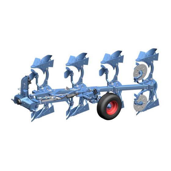
Layout and description LAYOUT AND DESCRIPTION Overview 1 Three-point linkage 8 Working tools (skimmer, trash board) 2 Drawbar 9 Disc coulters 3 Turnover device 10 Lighting system 4 Optiquick adjustment system 5 Base frame 6 Land wheel 7 Plough body Description 5.2.1 Three-point linkage The three-point linkage with upper link pin and drawbar corresponds to ISO 730. -
Page 34: Turnover Device
The plough line and the front furrow width can be adjusted independently. This permits ploughing without lateral force at every working width. 5.2.4 Base frame The ploughs of the Juwel 7 series are equipped with a box section frame 120 x 120 x 10 mm. The frame height is 80 cm. -
Page 35: Plough Body
Layout and description 5.2.6 Plough body DuraMaxx The mould boards (1) or slats (2) are at- tached to the body (4) with hooks (3). This means that they can changed without hav- ing to use tools. This cuts the time required by up to 80%. -
Page 36: Working Tools
Layout and description 5.2.7 Working tools The following working tools are available as accessories: Trash board (1) Skimmer (2) Coulter (3) -
Page 37: Disc Coulters
Layout and description 5.2.8 Disc coulters The large, beaded (1) disk coulter provides for a clean furrow. 5.2.9 Lighting system The lighting system contributes significantly to increasing the safety of the imple- ment in road traffic. -
Page 38: Preparations On Tractor
Preparations on tractor PREPARATIONS ON TRACTOR Tyres The air pressure must be identical, particularly on the rear tractor tyres. Under dif- ficult conditions, additional wheel weights should be used or the tyres topped up evenly with water. See operating instructions of the tractor manufacturer. Lifting rods The lifting rods should be adjusted so they are as short as possible and of equal length. -
Page 39: Required Hydraulic Equipment
Preparations on tractor Required hydraulic equipment The implement is supplied as standard with separate hydraulic connections for each consumer. The protective caps for the hydraulic connections are colour- coded and the hydraulic connections themselves are alphanumerically coded. For operation of the specific hydraulic equipment listed below, the tractor must be equipped with the following control units: Consumers Double-acting... -
Page 40: Installing The Button
Preparations on tractor Installing the button CAUTION The button must not be mounted together with a magnet or in the vicinity of a magnet. A magnet has a negative effect on the functioning of the button. Accidental switching may result. ... -
Page 41: Use
General Instructions Before the first use it is recommendable - with fully lowered implement - to carry out the following adjustments at the farm and to make familiar with the machine and its functions. Afterwards only few adjustment corrections have to be carried out in the field. -
Page 42: Three-Point Attachment
Three-point attachment Loss of the implement The category of the three-point linkage of the tractor and the cate- WARNING gory of the drawbar and the upper linkage bolts must match. The drawbar and the upper linkage bolts can otherwise slip out of the connection when driving over unevenness or due to vibration. -
Page 43: Attaching And Detaching
Attaching and detaching ATTACHING AND DETACHING Risk of injury for lowered implement Never enter the danger area between the tractor and the im- plement WARNING Read and follow the instructions in the "General Health and Safety Precautions" section and the specific safety instructions "Risks posed by lowered implement". - Page 44 Attaching and detaching Connect the upper linkage so that it rises towards the plough during the ploughing. Secure the upper link bolt (6). Use only the upper link bolt supplied with the plough. If the ground conditions are hilly, connect the upper linkage for 5-furrow ploughs using the oblong hole so that the upper linkage ideally touches in the front in the oblong hole during the plough- ing.
-
Page 45: Detaching
Attaching and detaching Detaching Detach the plough from the tractor as fol- lows: The plough should be in the covering work- ing position. Always place the plough onto firm and level ground. Set the tractor hydraulics to position con- trol. - Page 46 Attaching and detaching Unlock the lower linkage locking mecha- nism. Lower the plough completely. Check whether the lower linkages are completely disconnected from the draw- bar. The three point linkage (7) stands at an angle when the plough is lowered which can make reattachment later more difficult.
-
Page 47: Operation
Operation OPERATION Turning the plough frame Refer to the Refer to the Safety measures and precautions, see page 13. DANGER Before each rotation, ensure that there are no persons in the turning and swivelling area of the plough. ... -
Page 48: Adjustments
Adjustments ADJUSTMENTS Read and follow the section entitled "Safety and protection measures. The implement may only be used, maintained and repaired by CAUTION people who are familiar with it and who are aware of the haz- ards involved. ... -
Page 49: Front Furrow Width
Adjustments 10.1 Front furrow width 10.1.1 General information The front furrow width must be set to correspond to the working width of the fol- lowing plough base with the Optiquick setting system. 10.1.2 Front furrow width, mechanical Front furrow too narrow ... -
Page 50: Front Furrow Width, Mechanical, In Conjunction With Hydraulic Frame Swivel
Adjustments 10.1.3 Front furrow width, mechanical, in conjunction with hydraulic frame swivel In conjunction with the hydraulic frame swivel, the base frame DANGER first swivels in and then out again before the turn. A pinch point is located between hydraulic cylinder and the ad- juster sleeve. -
Page 51: Front Furrow Width, Hydraulic
Adjustments Re-tighten the clamping screw (2), see «Tightening torques, page 86». Retract the hydraulic cylinder again. The connection T1 of the rotary cylinder is pressurised. 10.1.4 Front furrow width, hydraulic In place of the outer spindle, a hydraulic cylinder (1) with installed sensor is used via which the front furrow width can be set hydraulically. -
Page 52: Tractor Ploughing Line
Adjustments Press the yellow button (2). The LED in the button lights up. During ploughing, set the desired front furrow width via the control unit. If the desired width has been reached, you have two options: Store the front furrow width: ... -
Page 53: Angle
Adjustments 10.3 Angle 10.3.1 General information When ploughing, the base blade should be almost vertical to the ground as seen from the direction of travel. The correct angle is set when the ploughing pattern is uniform. If this is not the case, then the angular adjustment must be altered as described below. -
Page 54: Working Depth
Adjustments You now have two options: Save the angular position. Hold down the button (1) until the LED goes out = min. 3 seconds. After every rotation, the saved angle is automatically restored. Set the angle once. Briefly press the button (1). When you release it, the LED goes out. After the next rotation, the last saved angle is automatically restored. -
Page 55: Hydraulic Frame Swivel
Adjustments 10.5 Hydraulic frame swivel WARNING Observe the general health and safety precautions »3.10.3, hy- draulic systems», page 29. The frame swivel cylinder (1) is connected via to hydraulic hoses with the control block in the three-point linkage. The base frame can be swivelled in and out again during the turn automatically without the previously set front furrow width being influenced. -
Page 56: Duramaxx Plough Body
Adjustments The three-point linkage of the tractor is off- set laterally for a change of the working width of the Juwel V for the automatic ad- aptation of the front furrow width and the tractor plough draught line. Observe that the limit chains always permit a sufficient lateral movement of the lower linkages. -
Page 57: Working Width For Each Base
Adjustments 10.7 Working width for each base 10.7.1 Juwel V Once the basic plough settings have been made with the OPTIQUICK adjusting cen- tre, the working width for each base can be changed as required from the tractor seat using the working width adjusting cylinder (1). -
Page 58: Landside
Adjustments 10.8 Landside To achieve better control on a slope, the landside (1) can be set to a lower position. Undo the screw Remove the screw (2). Set the landside (1) to its lowest posi- tion. Replace the screw (2). Standard assembly ... -
Page 59: Adjustment Of The Projection Angle
Adjustments 10.9.2 Adjustment of the projection angle The projection angle of the skimmer (1) must be adjusted by changing the position of the locking bar (2). Release the pin (3). Pull the pin (3) out. Remove the locking bar (2). ... -
Page 60: Working Depth
Adjustments 10.9.3 Working depth Risk of crushing CAUTION When setting the working depth, the skimmer may drop down when the pin (4) is removed. Hold on to the skimmer with one hand until you have secured it by inserting the pin. Adjusting the working depth does not change the projection angle setting. -
Page 61: Trashboard
Adjustments 10.10 Trashboard Screw the trashboard (1) and retainer (2) onto the base blade (3). The retainer (2) has slots (4) to allow uni- versal adjustment. 10.11 Landside coulter Remove the landside wedge (1) before retrofitting the landside coulter. - Page 62 Adjustments Screw on the landside coulter (2) before the landside (3). Tighten screws again. «Tightening torques, page 86».
-
Page 63: Disc Coulters
Adjustments 10.12 Disc coulters 10.12.1 General The disc coulters are designed to work at a depth of approx. 7 - 9 cm and run about 2 - 3 cm to the side of the vertical slat edge. 10.12.2 Working depth To set the working depth of the disc coul- ter, proceed as follows: ... -
Page 64: Clearance To The Side
Adjustments 10.12.3 Clearance to the side The clearance between the side of the coulter (6) and the edge of the slat is set pivoting the stalk (7) or moving the pin in the oblong hole (11). Loosen the corresponding screws / nuts(1 or 8). -
Page 65: Swivel Limitation
Adjustments 10.12.4 Swivel limitation The swivelling range to the side of the disc coulter is set with the screw (9). Loosen the screw (9). Move the stop (10) into the required po- sition. Re-tighten screw (9), «Tightening torques, page 86». ... -
Page 66: Subsoiler
Adjustments 10.13 Subsoiler Fit the subsoiler as shown in the adja- cent illustration. Moving the blade (1) enables the working depth of the subsoiler to be adjusted to two positions. Release the subsoiler using a spring lock (2). ... -
Page 67: Depth Control Wheel And Depth And Transport Wheel
Adjustments 10.14 Depth Control Wheel and Depth and Transport Wheel 10.14.1 General Instructions The plough is available with depth control wheel (1) or depth and transport wheel. The depth and transport wheel is required when the front axle - especially for transport - is unloaded too much and so the steerability of the tractor is no more ensured. -
Page 68: Changing The Mechanical Depth And Transport Wheel From Working Position To Transport Position
Adjustments 10.14.2 Changing the mechanical depth and transport wheel from work- ing position to transport position Read and follow the instructions in the 'General Health and Safety Precautions' section and the specific safety instructions CAUTION 'Risks posed by hydraulic systems'. There are pinch points and shearing points located in the area of the wheel stops. - Page 69 Adjustments Swivel the locking pin (6) by 180° in the clockwise direction. Please ensure that you observe the sequence in the following: Never modify the working width while the plough is in a turning position. Raise the plough fully. ...
-
Page 70: Changing The Mechanical Depth And Transport Wheel From Transport Position To Working Position
Adjustments 10.14.3 Changing the mechanical depth and transport wheel from transport position to working position Connect the upper linkage to the head- stock. Secure the upper linkage with the upper linkage pin (7). Raise the plough slightly. ... -
Page 71: Changing The Hydraulic Depth And Transport Wheel From Working Position To Transport Position
Adjustments 10.14.4 Changing the hydraulic depth and transport wheel from working position to transport position Read and follow the instructions in the 'General Health and Safety Precautions' section and the specific safety instructions CAUTION 'Risks posed by hydraulic systems'. There are pinch points and shearing points located in the area of the wheel stops. - Page 72 Adjustments Raise the plough slightly using the three- point hydraulics. Release the pin (3) and pull it out. Swivel the wheel by 90°. Lock the wheel using the pin (3). Secure the pin (3) with the securing pin. ...
-
Page 73: Changing The Hydraulic Depth And Transport Wheel From Transport Position To Working Position
Adjustments 10.14.5 Changing the hydraulic depth and transport wheel from transport position to working position Connect the upper linkage to the head- stock. Secure the upper linkage with the upper linkage pin (6). Raise the plough slightly. ... -
Page 74: Working Depth Adjustment
Adjustments 10.14.6 Working depth adjustment Version with pin adjustment By moving the stop (1), the depth adjust- ment of the land wheel or depth and transport wheel is changed. If the stop (1) is moved towards the wheel axle (downwards), the working depth is in- creased. - Page 75 Adjustments Version depth and transport wheel with hydraulic adjustment Adjust the depth with the control unit of the tractor. The indicator (3) shows the set depth range. Depth and transport wheel It is recommended that you also adapt the setting of the tractor hydraulics in addition to the length setting of the upper linkage and the tilt setting after a working depth adjustment to prevent in- creased drag or a poor depth guidance.
-
Page 76: Overload Protection
Overload protection OVERLOAD PROTECTION 11.1 Shearing protection There are crushing and shearing points in the area of the shearing protection. DANGER Never remain in the plough base release area during ploughing work. The plough bases release upwards when the shear bolt is over- loaded. -
Page 77: Hydromatic Hydraulic Overload Protection
Overload protection Shear bolt Type of plough Dimension Juwel 7 M 14X75 LS 56X15 - 8.8 Juwel 7 V Juwel 7 T M 14X70 LS 51X15 - 10.9 Juwel 7 VT 11.2 Hydromatic hydraulic overload protection Read and observe the information in the "Safety and protective measures"... -
Page 78: Setting The Release Force
Overload protection 11.2.2 Setting the release force The hydraulic overload protection enables various operating pressures to be set; a low operating pressure should be selected for flat and easy ground conditions and a higher pressure for difficult ground conditions. Standard version The standard version has a shut-off valve below the pressure gauge. - Page 79 Overload protection Comfort version Available as an add-on, the minimum and maximum operating pressure can be saved. Any pressure between the two saved values can then be set during work. After connecting the adjusting valve unit to a control unit on the tractor, the system is ready to operate with the factory set maxi- mum and minimum operating pressure.
-
Page 80: Operation
Overload protection 11.2.3 Operation To protect the hydraulic system, the plough and the tractor itself, the lowest possi- ble operating pressure should always be used. The maximum operating pressure is set by applying pressure to connection A on the valve adjusting unit for several seconds. The minimum operating pressure is set by applying pressure to connection B on the valve adjusting unit for several seconds. -
Page 81: Packer Arm
Packer arm PACKER ARM CAUTION Read and observe the «Safety measures and precautions, page 13». The packer arm swivels to the catch position by spring force. Ensure that an adequate safety distance is maintained. Insert the packer arm (1) into the retain- ing slot (2) on the front of the plough frame. -
Page 82: Switching Off The Device
Switching off the device SWITCHING OFF THE DEVICE 13.1 Shutting down the device in an emergency In an emergency shut down the device via the tractor. Switch the tractor engine off. Remove the ignition key. Damage caused by improper storage of the device If incorrectly or improperly stored, the device may be damaged, CAUTION e.g. -
Page 83: Maintenance And Repairs
Maintenance and repairs MAINTENANCE AND REPAIRS 14.1 Special safety instructions 14.1.1 General Risk of injury when carrying out maintenance and repair work There is always the risk of injury when carrying out maintenance and repair work. WARNING Use suitable tools, suitable climbing aids, platforms and support elements. -
Page 84: Immobilise The Implement For Maintenance And Repairs
Maintenance and repairs 14.1.3 Immobilise the implement for maintenance and repairs Risk of accidents when tractor starts up Injuries may occur if the tractor starts moving during maintenance and repair work. Switch off the tractor engine before carrying out any work on the WARNING implement. -
Page 85: Protective Equipment
Maintenance and repairs 14.1.6 Protective equipment CAUTION Risk of accident due to working without protective equipment There is always an increased risk of accidents when carrying out maintenance work and repairs. Always wear appropriate protective equipment. 14.1.7 Utilised tool Risk of accident due to use of unsuitable tool WARNING If working with an unsuitable or defective tool, there is a risk of ac-... -
Page 86: Environmental Protection
The hydraulic hoses must be replaced at the latest 6 years after the date of manufacture. Use hydraulic ho- ses authorised by LEMKEN only. Safety equipment Check that the safety equipment functions properly. -
Page 87: Weekly Inspection
Maintenance and repairs 14.3.3 Weekly inspection Check What to do? Wheel nuts Check that all wheel nuts are tight and, if re- quired, retighten the wheel nuts to the appro- priate torque. Screw connections Retighten all other bolts and nuts on the device to the appropriate torque. -
Page 88: Tightening Torques
Maintenance and repairs 14.4 Tightening torques 14.4.1 General information Once loosened, secure self-locking nuts against self-loosening by exchanging the nuts with new self-locking nuts. using safety washers. using thread-locking compounds, such as Loctite. The following tightening torques refer to screw threaded fittings not specifically mentioned in these operating instructions. -
Page 89: Wheel Bolts And Wheel Nuts
Maintenance and repairs 14.4.3 Wheel bolts and wheel nuts Diameter / thread [Nm] M18 x 1,5 M20 x 1,5 M22 x 1,5 14.5 Air pressure of the tyres DANGER If the air pressure in the tyres is too high, the tyres may burst and if the air pressure is too low, the tyres may become overstressed. -
Page 90: Hydromatic Overload Protection - Depressurising The Hydraulic System
Maintenance and repairs 14.6 Hydromatic overload protection - depressurising the hydraulic sys- The hydraulic system must always be de- pressurised if service or repair work needs to be carried out, for example. To do this, the control unit of the tractor must be switched to floating position with the plough lowered and the relief valve (5), which is located behind a protective cap,... -
Page 91: Checking Connections To The Tractor
Maintenance and repairs 14.7 Checking connections to the tractor 14.7.1 Hydraulic connections Risk of accident due to spraying hydraulic fluid Fluid (hydraulic oil) escaping under high pressure can penetrate WARNING the skin and cause severe injuries. In case of injury, seek medical attention immediately. -
Page 92: Lubrication Chart
Maintenance and repairs 14.7.3 Lubrication chart Before and after long periods of operation Winter break Slewing gear bearings and cylinder adapters Optiquick adjustment centre Turn buckles Support and depth and transport wheel swivel axes Support and depth and transport wheel bear- ings Swivel brackets and control rod... -
Page 93: Troubleshooting
Troubleshooting TROUBLESHOOTING 15.1 Hydraulic equipment – TurnControl Fault Cause Remedy Plough does not start to turn. Restore the power supply. Power supply disconnected. The front furrow width chang- The piston seal on the frame Replace the piston seal. es while working. -
Page 94: Plough Intake And Depth Control, Slippage
Troubleshooting 15.3 Plough intake and depth control, slippage Fault Cause Remedy Plough does not remain in the Intake force too low. Pull in the base = Reduce ground. the distance between the share tip and the plough frame (not more than 2 cm). ... -
Page 95: Transport On Public Roads
Transport on Public Roads TRANSPORT ON PUBLIC ROADS 16.1 Laws and regulations All laws and regulations with regard to transport on public roads must be adhered 16.2 Warning Boards and Lighting Equipment If it is required to drive on public roads with the plough fitted to the tractor, fit warn- ing boards and lighting equipment. -
Page 96: Technical Data
52 -74 70 -100 Juwel 7 V / VT 59-96 80-130 Juwel 7 / 7 T 59-96 80-130 Juwel 7 V / 7 VT 59-96 80-130 Juwel 7 / 7 T 59-96 80-130 Juwel 7 V / 7 VT 66-118... - Page 97 Identification plate IDENTIFICATION PLATE The identification plate (1) is situated on the front of the three-point tower.
- Page 98 Index INDEX ADJUSTMENTS ....................46 Air pressure ......................87 Angular adjustment ....................51 Attaching ....................... 41 Axle loads ......................22 Contact angle ....................... 54 Depth and Transport Wheel.................. 65 Depth Control Wheel .................... 65 Detaching ......................43 Disc coulters ......................61 DuraMaxx ......................
- Page 99 Index Skimmer ......................39, 56 TECHNICAL DATA ....................94 Three-point attachment ..................40 Top Link ........................ 36 Transport ......................93 Trashboard ......................59 TROUBLESHOOTING..................91 Tyres ........................87 Use ........................39 Warning Boards ....................93 Warning signs ....................... 14 Weights ......................... 94 Working Depth ......................
Need help?
Do you have a question about the Juwel 7 and is the answer not in the manual?
Questions and answers