Table of Contents

Related Manuals for LEMKEN Zirkon 10


Summary of Contents for LEMKEN Zirkon 10
- Page 1 Operating Instructions Power Harrow Zirkon 10 - EN - Item no. 175_3753 2/01.12 LEMKEN GmbH & Co. KG Weseler Straße 5, D-46519 Alpen Telephone (0 28 02) 81-0, Fax (0 28 02) 81-220 E-mail: lemken@lemken.com, Internet: http://www.lemken.com...
- Page 3 However, this brief instruction is not a substitute for thorough study of the operating instructions. These operating instructions will help to familiarise you with the LEMKEN GmbH & Co. KG device and the options available for using it.
- Page 4 Remember that you should only use genuine LEMKEN spare parts. Reproduction parts have a negative influence on the function of the device, have a shorter ser- vice life and present risks and hazards that cannot be estimated by LEMKEN GmbH & Co. KG. They also increase the maintenance costs.
-
Page 5: Table Of Contents
Contents CONTENTS Contents ........................... 3 General information ....................9 Liability........................... 9 Guarantee........................9 Copyright ........................10 Optional accessories ....................10 Symbols used in the Operating Instructions............11 Hazard classes ......................11 Information........................11 Environmental protection ................... 11 Indication of passages....................12 Safety measures and precautions................. - Page 6 Contents 3.9.2 Requirements of the tractor..................22 3.9.3 Axle loads......................... 22 3.9.4 Check before departure ................... 27 3.9.5 Correct behaviour in road traffic ................27 3.10 Obligation of the operator ..................28 3.11 Operating the device safely..................29 3.11.1 General information ....................29 3.11.2 Personnel selection and qualifications..............
- Page 7 Contents Pendulum compensation.................... 39 Required hydraulic equipment................... 39 Required power sources..................... 40 Three-point linkage ..................... 41 Hydraulic system......................42 7.8.1 Transport........................42 7.8.2 Work assignment ..................... 43 7.8.3 Coupling and uncoupling..................43 Coupling and uncoupling..................44 Coupling........................44 Uncoupling........................47 Operation .........................
- Page 8 11.2 Adjusting the scrapers ....................77 11.3 Clearance between scraper and roller casing ............78 12 Mounting a LEMKEN seed drill ................79 12.1 Coupling partsfor mounting a Solitair seed drill ............79 12.2 Coupling parts for mounting Saphir Seed Drill ............79 12.3 Coupling A-frame ......................
- Page 9 Contents 14.3 Tube bar roller for front mounting ................86 15 Switching off the device ..................87 15.1 Shutting down the device in an emergency.............. 87 15.2 Disposal ........................87 16 Maintenance and repairs ..................88 16.1 Special safety instructions ..................88 16.1.1 General.........................
- Page 10 Contents 16.10.2 Bolts and nuts made of steel ................99 16.10.3 Bolts and nuts made of V2A ................100 16.11 Tines........................... 101 16.12 Scrapers ........................101 16.13 Cardan shaft ......................101 16.14 Hydraulic hoses......................102 17 Troubleshooting ....................103 17.1.1 General information ....................
-
Page 11: General Information
Co. KG, in particular Section IX, shall apply. Liability. In line with the dimensions cited in these conditions the LEMKEN GmbH & Co. KG shall not be held liable for any personal or material damage, when such damage is caused by one or more of the following reasons: ... -
Page 12: Copyright
Infringements will result in a claim for damages. Optional accessories LEMKEN implements may be equipped with various accessories. The operating instructions below describe both series components and optional accessories. Please note: These accessories will vary depending on the type of equipment. -
Page 13: Symbols Used In The Operating Instructions
Symbols used in the Operating Instructions SYMBOLS USED IN THE OPERATING INSTRUCTIONS Hazard classes The following symbols are used in the Operating Instructions for particularly im- portant information: DANGER Denotes an imminent hazard with high risk, which will result in death or severe physical injury, if not avoided. -
Page 14: Indication Of Passages
Symbols used in the Operating Instructions Indication of passages The following symbols are used for particular passages in the operating instruc- tions: Indicates work steps Indicates enumerations... -
Page 15: Safety Measures And Precautions
Safety measures and precautions SAFETY MEASURES AND PRECAUTIONS General safety instructions for the operator are specified in the chapter entitled "Safety measures and precautions". At the start of some main chapters the safety instructions, which refer to all work to be carried out in this chapter, are listed to- gether. -
Page 16: Safety Equipment On The Device
Safety measures and precautions Safety equipment on the device To protect the user and the device, the device features special safety equipment. Always keep all safety equipment in working order. Safety and warning signs 3.4.1 General information The implement features all equipment which ensures safe operation. - Page 17 Safety measures and precautions Before carrying out maintenance or repair work, switch off the engine and remove key. Do not remain in the operating and swivel area of the implement. Danger of crushing. Danger through moving machine parts. The power takeoff shaft drive-through runs to the right.
- Page 18 Safety measures and precautions Do not climb onto the implement. Do not touch any moving machine parts. Wait until they have come to a standstill. Hot surfaces When the three-point power lift is activa- ted, stay outside of the lifting range of the three-point suspension.
-
Page 19: Position Of The Safety And Warning Signs
Safety measures and precautions 3.4.3 Position of the safety and warning signs... -
Page 20: Special Safety Instructions
Safety measures and precautions Special safety instructions Risk of injury due to non-observance of the currently valid occupational safety guidelines If the currently valid occupational safety guidelines are bypassed WARNING or safety equipment is rendered unusable when handling the de- vice, there is a risk of injury. -
Page 21: Hazardous Areas
Safety measures and precautions Risk of injury when freeing casualties When rescuing people trapped or injured by the device, there is a risk of additional serious injury to the casualty if the hydraulic con- nections were not connected according to their colour coding as described in the section entitled "Required hydraulic equipment". -
Page 22: Hazardous Areas During Operation Of The Implement
Safety measures and precautions 3.6.1 Hazardous areas during operation of the implement Residual risks Residual risks are particular hazards which occur when handling the device and which cannot be eliminated despite a design in accordance with safety require- ments. Residual risks are not usually obvious and may be the source of a potential injury or health hazard. -
Page 23: Hazard Caused By Hydraulic Systems
Safety measures and precautions 3.7.2 Hazard caused by hydraulic systems There is a risk of injury to body parts, in particular the face, eyes and unprotected areas of skin, caused by burns and contamination with hydraulic fluid due to hot/pressurised hydraulic fluid spraying out of leaking joints or lines, ... -
Page 24: Requirements Of The Tractor
Safety measures and precautions 3.9.2 Requirements of the tractor Ensure that the tractor with mounted device always reaches the stipulated brak- ing deceleration. Observe the permitted axle loads, gross weights and transportation dimensions, see also section entitled "Axle loads"! Observe the permitted power limit of the tractor! Risk of accidents due to inadequate steerability A tractor which is too small or which has inadequate front ballast... - Page 25 Safety measures and precautions The following data are required for the calculation: from the tractor operating instructions, from the implement operating instructions, which are to be documented through remeasuring. Data from tractor operating instructions Take the following data from your tractor's operating instructions: Abbreviation Data Tractor kerb weight (kg)
- Page 26 Safety measures and precautions Data from implement operating instructions Take the following data from these operating instructions or from the documents for the front weight or rear weight: Abbreviation Data Gross weight (kg) for rear mounting implement or _______ kg rear weight Gross weight (kg) for front mounting implement or _______ kg...
- Page 27 Safety measures and precautions Calculation of minimum ballasting value at front G for rear mounting V min implement x (c + d) – T x b + (0.2 x T x b) V min a + b Enter the calculated minimum ballasting value, as required at the front of the tractor, into the table.
- Page 28 Safety measures and precautions Calculation of actual rear axle load T H tat H tat V tat Enter the value for the calculated actual rear axle load and the permissible rear axle load as given in the tractor's operating instructions into the table. Tyre load-carrying capacity ...
-
Page 29: Check Before Departure
Safety measures and precautions 3.9.4 Check before departure Before driving with the implement raised, lock the control lever of the control unit; otherwise it may drop and the implement may be unintentionally lowered. Mount and check the transport equipment such as the lighting system, warning signs and protective devices. -
Page 30: Obligation Of The Operator
Safety measures and precautions 3.10 Obligation of the operator Before switching on the device, read the operating instructions. Follow the safety instructions! Wear appropriate protective clothing when carrying out any work on the device. Protective clothing must be tight-fitting! ... -
Page 31: Operating The Device Safely
Safety measures and precautions 3.11 Operating the device safely 3.11.1 General information Before starting work, familiarise yourself with all equipment and actuating ele- ments as well as their functions. Do not operate the device until all protective devices have been attached and are in the safety position. -
Page 32: Personnel Selection And Qualifications
Safety measures and precautions In the wider operating range of the device there is a risk of injury, e.g. from ejected stones. Before actuating hydraulic equipment (such as flap devices), ensure that there is nobody in the flap area. Risk crushing and/or shearing by remote power op- erated parts. -
Page 33: Hydraulic System
Safety measures and precautions 3.11.3 Hydraulic system The hydraulic system is under high pressure. When connecting hydraulic cylinders and motors, ensure that the specified hydraulic hose connection is used. When connecting the hydraulic hoses to the tractor hydraulics, make sure that the hydraulic system is depressurised on both the tractor and the implement. - Page 34 Safety measures and precautions Attach the chains to secure the cardan shaft guard against rotation. Before switching on the power take-off, ensure that the power take-off speed selected for the tractor is in line with the permitted speed for the implement. ...
-
Page 35: Handing Over The Device
Handing over the device HANDING OVER THE DEVICE As soon as the device is delivered, ensure that it corresponds with the order package. Also check the type and completeness of any supplied accessories. When the device is handed over, your dealer will explain how it works. ... -
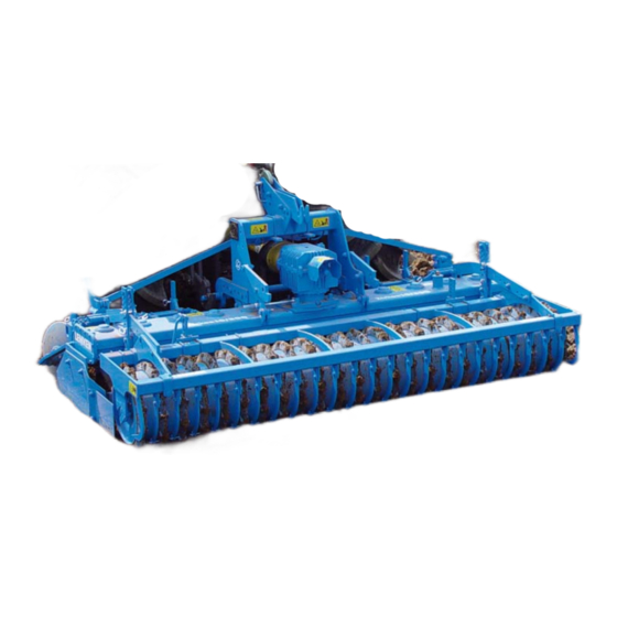
Page 36: Design And Function
Design and function DESIGN AND FUNCTION Overview 5 Power takeoff shaft drive-through 1 Three-point headstock 2 Gearbox recess 6 Roller 3 Knife tines 7 Levellingbeam 4 Side blade... -
Page 37: Function
The three-point tower with top link pin and drawbar complies with ISO 730. The drawbar L2/Z2 complies with category 2. Drawbar L3/Z3 complies with category 3. Drawbar L2/Z3 complies with category 3N. Description Upper link pin Zirkon 10/300 Cat. 2 or 3 Zirkon 10/350 Kat. 3 Zirkon 10/400 Cat. 3 5.2.2 Gear trough... -
Page 38: Power Takeoff Shaft Drive-Through
Design and function 5.2.4 Power takeoff shaft drive-through The rotational speed and direction of rota- tion for the power takeoff shaft drive- though (1) corresponds to the rotational speed and direction of rotation for the trac- tor power takeoff shaft. The 1 3/8“ 6-part drive-through serves, e.g. -
Page 39: First Use
First use FIRST USE CAUTION Always wear safety shoes when performing any adjusting work. Before work starts, all safety devices must be checked to make sure that they are working properly and then used or operated in accordance with these operating instructions. -
Page 40: Rear Levelling Beam
First use Rear levelling beam Before adjusting the levelling beam, always move the side blades into the working position. The rear levelling beam (4) must be ad- justed so that it is approx. 2 cm above the ground. It must be positioned even higher if too much soil is banked up. -
Page 41: Preparation Of The Tractor
Preparation of the Tractor PREPARATION OF THE TRACTOR Tyres The pressure - especially in the rear tractor tyres - must be equal. In heavy condi- tions it may be necessary to add wheel weights and/or water ballast. (See manu- facturer’s instructions). Lift Rods Adjust lift rods to equal length. -
Page 42: Required Power Sources
Preparation of the Tractor Required power sources Damage to electrical components The tolerance range for the power supply is between 10 V and 15 CAUTION V. Overvoltage and undervoltage will result in malfunctions and under certain circumstances may destroy electrical or electronic components. -
Page 43: Three-Point Linkage
Preparation of the Tractor Three-point linkage Danger to life if three-point linkage category is too small If a drawbar or a top link pin is used with a category that is too small, these components may be overloaded and break. As a re- sult, the implement may fall down and injure or kill people in the DANGER immediate vicinity. -
Page 44: Hydraulic System
Preparation of the Tractor The table below shows the maximum permissible tractor power outputs and di- mensions for each category as per ISO 730-1. Tractor power Pintle diameter of Length of drawbar (shoul- Zirkon Cat. drawbar [mm] der distance) [mm] 10/300 66 - 92 90 - 125... -
Page 45: Work Assignment
Preparation of the Tractor 7.8.2 Work assignment For use on the land switch the hydraulic system of the tractor to float position or mixed control. See operating instructions of the tractor manufacturer. 7.8.3 Coupling and uncoupling Lowering or raising the three-point linkage CAUTION If the three-point linkage moves uncontrollably due to an incorrect setting or operation, the operator may be injured. -
Page 46: Coupling And Uncoupling
Coupling and uncoupling COUPLING AND UNCOUPLING Before mounting and dismounting always: DANGER switch off the PTO shaft and tractor engine. pull on the handbrake. remove the ignition key. Coupling Risk of injury when coupling the device WARNING There is a risk of body parts being crushed between the tractor and device The tractor must be secured against unintentionally rolling away. - Page 47 Coupling and uncoupling Risk of injury from unsecured top link pin If the top link pin is not secured, it may slip out or get lost. CAUTION As a result, the device may fall down or be damaged. As a result, people in the immediate vicinity may be injured. ...
- Page 48 Coupling and uncoupling Switch the tractor's three point linkage to position control. Connect the tractor's lower control link to the implement’s drawbar (1). Lock the lower control link. Mount the upper control link such that it rises slightly towards the implement while operating.
-
Page 49: Uncoupling
Coupling and uncoupling Uncoupling The circular spike harrow must always be parked on solid and level ground. In combination with a hydraulic three-point linkage and mounted seed drill the hy- draulic three-point linkage with the seed drill must be fully lowered before disman- tling the circular spike harrow. -
Page 50: Operation
Operation OPERATION Turning at the headland DANGER Risk of damage to components If the implement is not fully raised, there is a danger that compo- nents may be damaged during an improper turn at the headland. Before turning at the headland the implement must be completely raised before turning-in to avoid any damage to the implement. -
Page 51: Power Take-Off
Operation Power take-off The tractor's power take-off may not be switched on until the power harrow has been lowered until it is only a few centi- metres above the ground and the side bla- des (1) prevent any penetration into the rotating tools. -
Page 52: Adjustments
Adjustments ADJUSTMENTS Risk of accident when making adjustments When making any adjustments to the device, there are risks of crushing, cutting, clamping and striking your hands, feet and body on heavy and occasionally compressed and/or sharp-edged parts. Always park implement on the ground. DANGER ... -
Page 53: Cardan Shaft
Adjustments DANGER Switch off the power take-off before carrying out adjustment work. 10.1 Cardan shaft 10.1.1 General information The Zirkon circular spike harrows are equipped with a cardan shaft with cam shift- ing clutch as an overload safeguard. Care must be taken to ensure that the car- dan shaft protection (3) is secured against also rotating by hooking-in the chains (4). - Page 54 Adjustments If the cardan shaft (5) does not meet the requirements listed here, then for a car- dan shaft (5) that is too long: 1. The distance of the circular spike harrow to the tractor must be increased or 2. The cardan shaft must be professionally shortened. If, by contrast, the cardan shaft is too short, then the distance of the circular spike harrow to the tractor must be reduced or a longer cardan shaft of the same make installed.
-
Page 55: Changing The Distance Between The Implement And The Tractor
Adjustments 10.1.2 Changing the distance between the implement and the tractor Before changing the distance between the implement and the DANGER tractor, you must perform the following steps: Switch off the power take-off and tractor engine. Apply the handbrake. ... -
Page 56: Shortening The Cardan Shaft
Adjustments 10.1.3 Shortening the cardan shaft Pull the two cardan shaft halves apart. Hold the two cardan shaft halves against one another with the shortest possible gap between the tractor and the imple- ment. On the outer protective tube, mark the length you need to cut off. -
Page 57: Manual Gearbox
Adjustments Hold the cut section of the inner protecti- ve tube (2) over the inner profile tube (9) and cut off the inner profile tube (9) at right angles. Deburr and clean the outer and inner profile tubes. ... -
Page 58: Rotor Speeds
Adjustments 10.2.2 Rotor speeds The following rotor speeds are possible, depending on the power take-off speed: Variant 1 Variant 2 If the cardan shaft's overload coupling responds too quickly on non-stony ground, at a power take-off shaft speed of 540 rpm or 750 rpm, then the power take-off shaft speed of 1000 rpm with matching gear must be selected. - Page 59 Adjustments For a normal gearbox: Shifting lever (2) in position (3) = rotor speed 330 rpm with 1000-rpm power take- off speed. Shifting lever (2) in position (4) = rotor speed 440rpm with 1000-rpm take-off speed. For a slow gearbox: Shifting lever (2) in position (3) = rotor speed 330 rpm with 1000-rpm power take- off speed.
- Page 60 Adjustments The recommended working speed for the rotor speeds is available in the following diagram. Recommended working speed depending on rotor speed Rotor speed per minute The rotor speed can be changed using the shifting lever. The 1000 rpm power take-off speed should always be selected. If a power take-off speed of 540 rpm or 750 rpm is used, then the input torque increases by 85 % or by 33 % and it does so at the same power transfer.
-
Page 61: Horizontal Position
Adjustments 10.3 Horizontal position During work, the implement should be horizontal. The adjustment required to en- sure this is made by adjusting the length of the tractor's upper link. If the tractor's power take-off is at a downwards or upwards incline towards the rear instead of parallel with the ground, the implement must be adjusted using the tractor's upper link so that the gearbox input shaft, when lowered into the working position, is parallel with the power take-off. -
Page 62: Knife Tines With Quick-Coupling System
Adjustments 10.5 Knife tines with quick-coupling system When the bar (2) is unlocked, it is easy to change the tines (1) manually as fol- lows; CAUTION The safety stirrup is under enormous spring tension. It may only be lifted back with a suitable tool such as a screwdriver. ... - Page 63 Adjustments New knife tines with quick-coupling system are mounted in the reverse order to the order described above. They are inserted into the tine carrier (4) and then pushed inwards. Secure tines with the bar (2). The bar (2) is locked by lifting back the safety stirrup (3).
-
Page 64: Change In The Direction Of Rotation Of The Rotors
Adjustments 10.6 Change in the direction of rotation of the rotors The direction of rotation may only be changed when the tractor power take-off is switched off and the tractor engine is at a standstill. The direction of rotation of the rotors with quick-change tines can be changed by moving the gearbox (1) to the side. - Page 65 Adjustments Carefully clean the area around the gearbox flange (2). Remove all of the protective caps (3). Undo all of the centring nuts (4) until they are flush with the stud (5). Rotate the discs (6) by 180°. ...
-
Page 66: Side Blade
Adjustments 10.7 Side blade Move the side blade into the working position before working with it. The height of the spring-mounted side blades (2) is to be adjusted such that they cover the rotating tools completely. When worn they must be lowered accordingly. Once they have been lowered, tighten the bolts (3) again. - Page 67 Adjustments Then fold up the side blades (2). Lock the side blades in place using the guide pin (6). Secure the guide pin (6) using a spring pin (7).
-
Page 68: Extending The Side Blades
Adjustments 10.7.2 Extending the side blades Before the next work assignment and befo- re the tractor power take-off is switched on, the side blades (2) must be folded down as follows: Remove the spring pin (7) and guide pin (6). -
Page 69: Side Blade Extension
Adjustments 10.8 Side blade extension Bolt the side blade extensions (4) at the rear onto the side blades (2). After undoing the bolts (5) each side blade extension in the slots, under the washers (6), can be moved slightly forward or backward! The distance to the roller should be as small as possible. - Page 70 Adjustments 10.9.2 Adjusting the working depth The wheelmark eradicators are set to approx. 5 cm deeper than the bout of the tractor. Adjust the working depth of the wheelmark eradicator as follows: Raise the implement to relieve the load- ing on the wheelmark eradicator (1).
- Page 71 Adjustments 10.10.1 Relocation at the side On the bracket (3), move the feed disc (1) to the required working width. Tighten the bolts (4) to a torque of 197 Nm. 10.10.2 Adjusting the working depth Unlock the pin (5). ...
- Page 72 Adjustments 10.11 Protective equipment To ensure that the implement can be used safely, the safety equipment must al- ways remain in place. If the implement is retrofitted with a rear levelling beam (2), the roller (3) must be mounted at a greater distance from the implement. This also means that the straight protective bar (4) must be replaced by a curved protective bar.
- Page 73 Adjustments Without levelling machine but with roller and seed drill = roller mounted in rear posi- tion, protective tube (1) fitted 10.12 Power take-off The tractor's power take-off may not be switched on until the rotary harrow has been lowered until it is only a few centi- metres above the ground and the side bla- des (1) prevent any penetration into the rotating tools.
- Page 74 Adjustments 10.13 Levelling beam CAUTION Before adjusting the levelling beam, always move the side blade into the working position. The circular spike harrow can be equipped at the rear or front with a levelling beam (1). 10.13.1 Rear-mounted levelling beam Set the levelling beam (1) using the rough- turning gauge (2) so that the lower edge of the levelling beam is about 2 cm over the...
- Page 75 Adjustments 10.14 Track markers CAUTION Before operating the track marker always make sure that no-one is standing in the danger zone. For a more precise access run for the cir- cular spike harrow, in particular, in combi- nation with a seed drill, track markers are available that can be bolted onto the carri- ers (2).
- Page 76 Adjustments Find the adjusting dimensions in the following table. The dimensions refer to a marking groove in the centre of the tractor track. Zirkon Distance from middle of seed drill to Distance from outer seeding track groove coulter 10/300 300 cm 150 cm + ½...
- Page 77 Adjustments 10.14.1 Shear device The track marker is safeguarded against overloading by a shear bolt (9). If a shear bolt fractures, the remains of the bolt must be removed first before a new shear bolt is fitted. Use M10x45 / 8.8 shear bolts only with article number 301 3240.
- Page 78 Rollers ROLLERS 11.1 General information The Zirkon can be fitted with a range of rollers: Tube bar roller RSW 400 or RSW 540 Trapeze packer roller TPW 500 Trapezoidal disc roller TSW 500 Toothed packer roller ZPW 500 Tube bar rollers are maintenance-free.
- Page 79 Rollers 11.2 Adjusting the scrapers The adjustable scrapers (1) for the size 500 rollers are adjusted using setting nuts (2) or eccentric nuts (3). Adjust the setting nuts (2) for the toothed packer rollers using a 19 mm wrench and the eccentric nuts (3) using a 24 mm wrench.
- Page 80 Rollers 11.3 Clearance between scraper and roller casing The clearance between the scraper (1) and the roller casing (5) must be set in line with the following schedule. The adjusting instructions apply to all toothed packer rollers, trapezoidal packer rollers and trapezoidal disk rollers. Heat-treated scraper (1) Plastic scraper (1) (must make contact with roller casing (5)
- Page 81 Mounting a LEMKEN seed drill MOUNTING A LEMKEN SEED DRILL 12.1 Coupling partsfor mounting a Solitair seed drill Zirkon circular spike harrows are available with coupling parts for attaching a Soli- tair seed drill. The coupling parts come with a top safety hook (1) and two lower support plates (2).
- Page 82 Mounting a LEMKEN seed drill 12.3 Coupling A-frame A corresponding coupling A-frame (4) is available for mounting seed drills equipped with a coupling A-frame.
- Page 83 Hydraulic excavation linkage HYDRAULIC EXCAVATION LINKAGE 13.1 Adaptation of hydraulic excavation linkage To achieve the most favourable centre-of- gravity attachment of a mounted device, e.g. a seed drill, the lower control arms (1) can be shortened by adjusting their length. The bore line (2) can be used for this pur- pose.
- Page 84 Hydraulic excavation linkage 13.2 Mounting an attachment WARNING Danger of tipping After setting the length of the upper link (8), secure the upper link with the locknut. Perform the following steps to mount an attachment: Pull out the spring pin (6). ...
- Page 85 Hydraulic excavation linkage With the attachment raised, close the shut-off valve (9). 13.3 Lowering the attachment Lower the attachment (seed drill) as fol- lows: Open the shut-off valve (9) with the trac- tor control unit locked. Switch the tractor control unit to the "Lo- wer"...
- Page 86 Hydraulic excavation linkage 13.4 Hoisting limiter The excavation height of the implement attached to the circular spike harrow can be limited. A hoisting limiter is available for the hydraulic excavation linkage. The hoisting limiter consists of a shift valve (1) and a control rod (2), which is connec- ted to the excavation linkage's hydraulic cylinder.
- Page 87 Front mounting FRONT MOUNTING 14.1 Add-on parts for pusher on heavy-duty excavation linkage Zirkon can also be used in a front-mounted position. Add-on parts (1) are avail- able for this purpose, if the Zirkon has already been equipped with a dual-acting hydraulic excavation linkage.
- Page 88 Front mounting 14.2 Pusher , heavy duty version The pusher (4) is mounted at the rear to the circular spike harrow's three-point tower using the upper link (5). It is recom- mended for use if the circular spike harrow is to be used in front mounting position only.
- Page 89 Switching off the device SWITCHING OFF THE DEVICE 15.1 Shutting down the device in an emergency In an emergency shut down the device via the tractor. Switch the tractor engine off. Remove the ignition key. Damage caused by improper storage of the device If incorrectly or improperly stored, the device may be damaged, CAUTION e.g.
- Page 90 Maintenance and repairs MAINTENANCE AND REPAIRS 16.1 Special safety instructions 16.1.1 General Risk of injury when carrying out maintenance and repair work There is always the risk of injury when carrying out maintenance and repair work. WARNING Use suitable tools, suitable climbing aids, platforms and support elements.
- Page 91 Maintenance and repairs 16.1.4 Immobilise the implement for maintenance and repairs Risk of accidents when tractor starts up Injuries may occur if the tractor starts moving during maintenance and repair work. Switch off the tractor engine before carrying out any work on the WARNING implement.
- Page 92 Maintenance and repairs 16.1.7 Working under the raised device Risk of accident due to lowering and extending of compo- nents and devices It is extremely dangerous to work under raised or next to retracted WARNING components and devices. Always secure the tractor to prevent it from rolling away. Re- move the ignition key and secure the tractor to prevent it from being started up by unauthorised persons.
- Page 93 Maintenance and repairs Risk of accident due to tool slipping off If applying a large force, e.g. when loosening bolts, the tool may WARNING slip off. This may result in hand injuries on sharp-edged parts. Avoid applying a large force by using suitable auxiliary equip- ment (e.g.
- Page 94 Replace damaged or defective hydraulic hoses im- mediately. The hydraulic hoses must be replaced 6 years after the date of manufacture at the latest. Only used hydraulic hoses approved by Lemken. Check that all safety equipment is functioning pro- Safety equipment perly.
- Page 95 Maintenance and repairs 16.4 Checking connections to the tractor 16.4.1 Hydraulic connections Risk of accident due to spraying hydraulic fluid Fluid (hydraulic oil) escaping under high pressure can penetrate WARNING the skin and cause severe injuries. In case of injury, seek medical attention immediately.
- Page 96 Maintenance and repairs 16.5 Oil changing 16.5.1 Manual gearbox Before changing oil or checking the oil le- vel, the circular spike harrow must be par- ked on level and horizontal ground. Check the gearbox's oil level daily. The oil must always reach up to the check screw (2) for each gearbox.
- Page 97 Maintenance and repairs 16.5.2 Oil change intervals First oil change after 50 operating hours All other oil changes after 500 operating hours, but no later than once per an- Pay attention to cleanliness when changing oil. Dispose of drained oil in proper manner.
- Page 98 Maintenance and repairs Free-flowing grease When changing the free-flowing grease, the following quantities must be complied with: Zirkon 10/300 38 l Olit 00 (BP) Zirkon 10/350 41 l Olit 00 (BP) Zirkon 10/400 44 l Olit 00 (BP) When changing the free-flowing grease, make sure that work is car- ried out cleanly.
- Page 99 Maintenance and repairs 16.7 Lubrication The lubricating points must be lubricated in accordance with the maintenance chart using universal lubricating grease. Lubrication chart Every 25 Every 50 Before a winter After a winter break break Operating hours Track marker disk bea- ring (2x) Hydr.
- Page 100 Maintenance and repairs 16.8 Rotor bearings The rotor bearings have to be regularly inspected with regard to bearing clearan- ce. During the first 1000 operating hours they have to be inspected at least every 200 operating hours and then every 20 operating hours. If any discernible increa- se in bearing clearance is detected then the bearing in question has to be repla- ced to prevent any damage being caused to the gears in the gear housing and the gear housing itself.
- Page 101 Maintenance and repairs 16.10 Tightening torques 16.10.1 General information Once loosened, secure self-locking nuts against self-loosening by exchanging the nuts with new self-locking nuts. by using safety washers. by using thread-locking compounds, such as Loctite. The following tightening torques refer to screw threaded fittings not specifically mentioned in these operating instructions.
- Page 102 Maintenance and repairs 16.10.3 Bolts and nuts made of V2A Diameter [Nm] 1.37 11.0 M 10 M 12 M 14 M 16 M 18 M 20 M 22 M 24 M 27...
- Page 103 Maintenance and repairs 16.11 Tines Worn tines are to be replaced in good time. Risk of accident when implement lowered Performing work under raised components/implements or next to WARNING swivelled-in components/implements is life-threatening. Always secure the tractor against rolling away, remove the igni- tion key and and secure the tractor against any unauthorised start-up.
- Page 104 Maintenance and repairs 16.14 Hydraulic hoses Check hydraulic hoses regularly. At least 6 years after the date stated on the hy- draulic hoses they must be changed. Porouse or defective hydraulic hoses must be changed immediately. Use hydraulic hoses only, which are accepted by Lem- ken! Important: Do not clean this implement with a Pressure Washer during the first 6 weeks.
- Page 105 Troubleshooting TROUBLESHOOTING Before carrying out troubleshooting, it is essential to ensure that CAUTION the implement is parked on the ground the power take-off and tractor engine are switched off the ignition key is removed. Only then can the fault be repaired. 17.1.1 General information Fault Cause...
- Page 106 11027 are available for mounting this ligh- ting system. The Zirkon 10/400 + 10/350 circular spike harrows are wider than 3 m. On the Zirkon 10/300 + 10/350 the side blades must be folded-in before being transported. For transportation on public highways the...
- Page 107 TECHNICAL DATA TECHNICAL DATA Zirkon 10 Working width [cm] Number of rotors 1.035 1.149 Weight [approx. kg] 1.375 1.564 1.752 Weight with toothed packer roller [ap- prox. kg]...
- Page 108 Noise, Airborne Sound NOISE, AIRBORNE SOUND The noise level of the implement does not exceed 70 dB (A) during work. NOTES As the version of equipment is depending from the order, the equipment of your implement and its description concerned may deviate in some cases. To ensure a continuously updating of the technical features, we reserve the right to modify the design, equipment and technique.
- Page 109 Index INDEX Axle loads ......................22 Cardan shaft ......................51 Change in the direction of rotation of the rotors............ 62 Check Chains ....................... 39 Coupling ....................... 44 Coupling A-frame....................80 Coupling parts ...................... 79 DESIGN AND FUNCTION..................34 Feed discs ......................68 First use........................
- Page 110 Index Pusher ........................85 Pusher ........................86 Quick-coupling system ..................60 REPAIRS......................88 Rollers ........................76 Rotor speeds ......................56 Rotors ........................62 Scrapers ....................... 77 Seed drill....................... 79 Shear device......................75 Side blade......................64 Side blade extension .................... 67 Side blades......................
Need help?
Do you have a question about the Zirkon 10 and is the answer not in the manual?
Questions and answers