Table of Contents

Related Manuals for LEMKEN Heliodor 9 KA


Summary of Contents for LEMKEN Heliodor 9 KA
- Page 1 Operating Instructions Compact Disc Harrow Heliodor 9 KA - en - Item no. 17511408 03/03.22 LEMKEN GmbH & Co. KG Weseler Straße 5, 46519 Alpen / Germany Telephone +49 28 02 81 0, Fax +49 28 02 81 220 lemken@lemken.com, www.LEMKEN.com...
- Page 3 However, this brief instruction is not a substitute for thorough study of the operating instructions. These operating instructions will help to familiarise you with the LEMKEN GmbH & Co. KG device and the options available for using it.
- Page 4 Remember that you should only use genuine LEMKEN spare parts. Reproduction parts have a negative influence on the function of the device, have a shorter ser- vice life and present risks and hazards that cannot be estimated by LEMKEN GmbH & Co. KG. They also increase the maintenance costs.
-
Page 5: Table Of Contents
CONTENTS General information ....................10 Liability ......................... 10 Guarantee ........................10 Copyright ........................11 Optional accessories ....................11 Type plate ........................12 Symbols used in the Operating Instructions ............14 Hazard classes ......................14 Information ........................14 Environmental protection ................... 14 Indication of passages .................... - Page 6 Applicable rules and regulations ................31 Operation on public highways ................... 31 3.9.1 Lighting system and identification ................31 3.9.2 Requirements of the tractor ..................31 3.9.3 Permitted transport speed ..................32 3.9.4 Check before departure ..................... 33 3.9.5 Correct behaviour in road traffic ................33 3.10 Obligation of the operator ..................
- Page 7 Preparations on tractor ..................48 Tyres ..........................48 Lifting struts ........................ 48 Check Chains or Sway Blocks of the Three Point Linkage ........48 Power sources required....................48 Hydraulic equipment required ..................49 6.5.1 Implement with separate hydraulic connections ............50 6.5.2 Semi-mounted implements with 6/2-way directional control valve, with Solitair ..
- Page 8 10 Driving on public highways ................... 79 10.1 General information ....................79 10.2 Preparation for driving on public roads ..............79 10.3 Hydraulic transport lock ..................... 79 10.4 Shutoff valves ......................79 10.5 Protective devices ....................... 80 10.6 Lighting equipment and signs ................... 81 10.6.1 General........................
- Page 9 11.8 Wheelmark eradicator ....................101 11.8.1 Relocation at the side ................... 101 11.8.2 Adjusting the working depth ................. 102 11.9 Lateral draw ....................... 102 11.10 Lowering the chassis ....................103 11.10.1 General ......................103 11.10.2 Soil working implement with combination axle ..........103 11.10.3 Soil working implement with solo axle ...............
- Page 10 14 Using an implement with combination axle with an additional implement ..127 14.1 Removing the lighting equipment ................127 14.2 Coupling parts ......................128 14.3 Hydraulic three-point linkage ................... 129 14.3.1 Mounting an attachment ..................129 14.3.2 Lowering the attachment ..................130 14.3.3 Uncoupling the mounted implement ..............
- Page 11 16.9 Tightening torques ....................146 16.9.1 General......................... 146 16.9.2 Bolts and nuts made of steel ................146 16.9.3 Wheel bolts and wheel nuts .................. 147 16.10 Checking connections to the tractor ............... 147 16.10.1 Couplings ......................147 16.10.2 Connectors and cables ..................147 16.11 Replacing hollow discs .....................
-
Page 12: General Information
Co. KG, in particular Section IX, shall apply. Liability. In line with the dimensions cited in these conditions the LEMKEN GmbH & Co. KG shall not be held liable for any personal or material damage, when such damage is caused by one or more of the following reasons: ... -
Page 13: Copyright
Infringements will result in a claim for damages. Optional accessories LEMKEN implements may be equipped with various accessories. The operating instructions below describe both series components and optional accessories. Please note: These accessories will vary depending on the type of equipment. -
Page 14: Type Plate
General information Type plate The implement is marked with a type plate. The type plate is located at the front right of the implement. The operating instructions can apply to va- rious implement types implement equipment. In the operating instructions, contents are marked that are only valid for a certain im- plement type... - Page 15 General information 1 Series 2 Type designation 3 Model year 4 Serial number 5 Year of manufacture 6 Vehicle class, subclass, speed index 7 EU type approval number 8 Vehicle identification number. The vehicle identification number is also engraved in the frame near the type plate. 9 Permitted gross weight [kg]* 10 Permissible drawbar load [kg] (axle 0) 11 Permissible axle load [kg] (axle 1)
-
Page 16: Symbols Used In The Operating Instructions
Symbols used in the Operating Instructions SYMBOLS USED IN THE OPERATING INSTRUCTIONS Hazard classes The following symbols are used in the Operating Instructions for particularly im- portant information: DANGER Denotes an imminent hazard with high risk, which will result in death or severe physical injury, if not avoided. -
Page 17: Indication Of Passages
Symbols used in the Operating Instructions Indication of passages The following symbols are used for particular passages in the operating instruc- tions: Indicates work steps Indicates enumerations... -
Page 18: Safety Measures And Precautions
Safety measures and precautions SAFETY MEASURES AND PRECAUTIONS General safety instructions for the operator are specified in the chapter entitled «Safety measures and precautions». At the start of some main chapters the safety instructions, which refer to all work to be carried out in this chapter, are listed to- gether. -
Page 19: Safety Features Of The Device
Safety measures and precautions Clarify questions of comprehension concerning the contents of these operating instructions before starting work. To do this, contact the LEMKEN sales partner if required. Safety features of the device To protect the operator and the device, the device is equipped with special safety features in accordance with country specific requirements. - Page 20 Safety measures and precautions Safety chain Wheel chocks Hydraulic transport locking device Protection against unauthorised use: Cross shaft Protection against unauthorised use: Drawbar eye Protection against unauthorised use: K80...
-
Page 21: Safety And Warning Signs
Safety measures and precautions Safety and warning signs 3.4.1 General information The implement features all equipment which ensures safe operation. If hazardous areas could not be completely secured with respect to operational safety, warning signs are affixed which indicate these resi- dual risks. -
Page 22: Meaning Of Warning Signs
Safety measures and precautions 3.4.3 Meaning of warning signs Please familiarise yourself with the meaning of the warning signs. The following explanations provide detailed information. Please read and observe the operating in- structions and safety instructions before starting up the implement for the first time. Before carrying out maintenance or repair work, switch off the engine and remove key. - Page 23 Safety measures and precautions Keep out of the folding area of the device. When the three-point power lift is activated, stay outside of the lifting range of the three- point suspension. Hydraulic accumulator contains gas and oil under pressure. For removal and repair instructions in technical manual must be followed.
-
Page 24: Meaning Of Other Symbols
Safety measures and precautions Keep a sufficient distance away from elec- tric high-voltage lines. 3.4.4 Meaning of other symbols. Positioning points for jack Lock the lifting device Lock the lifting device before travelling on public roads. Unlock the lifting device before operati- Connection overview, hydraulic hoses P1 / T1 Hydraulic folding P2 / T2 Chassis... - Page 25 Safety measures and precautions Connection overview, hydraulic hoses (implement with 6/2-way directional control valve, with Solitair) Connection console P1 / T1 Coulter bar folding P3 / T3 Coulter bar lifting device or hydraulic three- point linkage P6 Hydraulic motor for fan (supply) T6 Hydraulic motor for fan (return line –...
- Page 26 Safety measures and precautions Hydraulic depth adjustment scale (only on implements with hydraulic depth adjustment)
-
Page 27: Special Safety Instructions
Safety measures and precautions Special safety instructions Risk of injury due to non-observance of the currently valid occupational safety guidelines If the currently valid occupational safety guidelines are bypassed WARNING or safety equipment is rendered unusable when handling the de- vice, there is a risk of injury. - Page 28 Safety measures and precautions Risk of injury when freeing casualties When rescuing people trapped or injured by the device, there is a risk of additional serious injury to the casualty if the hydraulic con- nections were not connected according to their colour coding as described in the section entitled "Required hydraulic equipment".
- Page 29 Safety measures and precautions Danger of tipping The tractor/implement combination may overturn: When folding in and out WARNING When driving on slopes This may result in accidents and people may be seriously injured or killed. When folding in and out, ensure that the implement is on a level surface.
-
Page 30: Danger Areas
Safety measures and precautions Danger areas 3.6.1 Danger areas during implement operation Moving danger area The danger area around the implement moves with the implement during operation. The danger area includes the area extending across the entire width (a) of the implement in the direction of WARNING travel. -
Page 31: Danger Areas When Folding And Unfolding
Safety measures and precautions 3.6.2 Danger areas when folding and unfolding Risk of impact and crushing from moving implement compo- nents There is a risk of impact or crush injuries from moving implement components. The danger area includes the area extending across the entire width of the implement (a). -
Page 32: Hazard Caused By Mechanical Systems
Safety measures and precautions Residual risks are not usually obvious and may be the source of a potential injury or health hazard. 3.7.1 Hazard caused by mechanical systems There is a risk of accidents due to crushing, cutting and striking body parts ... -
Page 33: Applicable Rules And Regulations
Safety measures and precautions Applicable rules and regulations The applicable rules which must be observed during operation of the device are listed below: Observe the currently valid national highway code! Observe the currently valid national laws and regulations for occupational safe- ... -
Page 34: Permitted Transport Speed
Safety measures and precautions Risk of accidents due to inadequate braking deceleration In the event of insufficient braking deceleration, the combination of tractor and implement will be unable to be braked or not be braked quickly enough. This may result in a rear-end collision, and DANGER the driver or other road users may be injured or killed. -
Page 35: Check Before Departure
Safety measures and precautions 3.9.4 Check before departure Check function of implement brakes before driving off. Before driving with the implement raised, lock the control lever, otherwise it may drop and the implement may be unintentionally lowered. Check that the fold-out safety device for the side parts is locked correctly. ... -
Page 36: Obligation Of The Operator
Safety measures and precautions 3.10 Obligation of the operator Before switching on the device, read the operating instructions. Follow the safety instructions! Wear appropriate protective clothing when carrying out any work on the device. Protective clothing must be tight-fitting! ... - Page 37 Safety measures and precautions Always attach the implement correctly and only attach it to the equipment provi- ded for that purpose. Always take great care when attaching the implement to and detaching it from the tractor. There is a risk of injury due to crush and shear points in the area around the three-point linkage.
-
Page 38: Personnel Selection And Qualifications
Safety measures and precautions 3.11.2 Personnel selection and qualifications The tractor driver must have the appropriate driving licence. All work on the implement must be carried out by properly trained and instructed personnel. The personnel must not be under the influence of drugs, alcohol or medication. -
Page 39: Handing Over The Implement
Handing over the Implement HANDING OVER THE IMPLEMENT As soon as the implement is delivered, ensure that it corresponds with the order package. Also check the type and completeness of any supplied accessories. When the device is handed over, your dealer will explain how it works. ... -
Page 40: Layout And Description
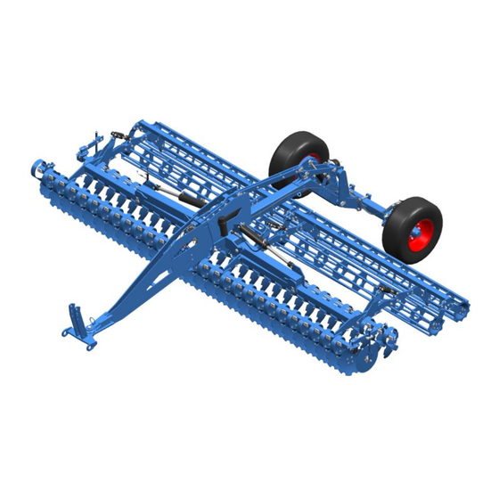
Layout and description LAYOUT AND DESCRIPTION The following assembly groups may be installed on the imple- ment, depending on implement model and national requirements. Overview Semi-mounted equipment / Trailer Lateral limiter Headstock Depth adjustment for concave discs Cross shaft Levelling tines Concave discs Rollers Foldable outer concave discs... -
Page 41: Function
Cross shaft L3/Z4 conforms to category 4N. 5.2.2 Combination axle The combination axle is needed if a LEMKEN Solitair seed drill is mounted on the implement using coupling parts or a different implement is mounted behind the implement using a three-point linkage. Both the coupling parts and the hydraulic three-point linkage are available as accessories and can be installed on the com- bination axle. -
Page 42: Rollers
Layout and description 5.2.6 Rollers The rollers ensure reconsolidation and additional crumbling of the soil. During op- eration on the field they bear the weight of the implement if the implement has been lowered for work and they ensure exact depth guiding. The weight of the rollers can also support the feed behaviour of the implement. -
Page 43: Coupling Elements
Layout and description 5.2.13 Coupling elements The coupling elements serve to mount the Solitair pneumatic seed drill to the im- plement with an optimum centre of gravity. This ensures that the soil can be culti- vated and the seeds can be sown in the same sequence of operation. 5.2.14 Hydraulic drawbar The hydraulic drawbar is optionally available for tractors with tractor drawbar or hitch ball. - Page 44 Layout and description Brake cylinder Brake lever Guiding screw Holder for guiding screw Brake lever...
- Page 45 Layout and description Function description Parking brake Only when the guiding screw (8) has been removed and placed and secured in the holder (9), is the parking brake ready for operation. The park valve (3b) is used as the parking brake. Activate parking brake: ...
- Page 46 Layout and description Shunting a tractor without compressed air supply: Attach the implement to a tractor. Secure the tractor and the implement to prevent them from rolling away. Release the parking brake. Pull out black button on the manoeuvring valve (3a).
-
Page 47: Hydraulic Braking System
Layout and description 5.2.16 Hydraulic braking system The hydraulic braking system is made up of the following components: Service brake Parking brake Shear brake Service brake The tractor's brake valve is used to operate the service brake hydraulically. Brake lever Compression spring for parking brake and rapid emergency brake... - Page 48 Layout and description Parking brake The parking brake prevents the implement rolling away. Brake coupling Break away cable (to the tractor) Brake valve Compression spring Activate parking brake: Manually pull the break away cable (2). Open the brake valve (3). Release the parking brake: ...
- Page 49 Layout and description Shear brake For driving on roads: Release the parking brake. Attach break away cable (2) to a stable location on the tractor. (Break away force approx. 60 kg). If the implement brakes away from the tractor, the break away cable (2) will auto- matically initiate an emergency stop.
-
Page 50: Preparations On Tractor
Preparations on tractor PREPARATIONS ON TRACTOR Tyres The air pressure must be identical, particularly on the rear tractor tyres. Under dif- ficult conditions, additional wheel weights should be used or the tyres topped up evenly with water. Refer to the operating instructions from the tractor manufactu- rer. -
Page 51: Hydraulic Equipment Required
Preparations on tractor The tractor must have the power sources listed below to supply the electrical con- sumers on the implement: Consumer Volt Directly connec- Power socket ted to the tractor battery Lighting equipment acc. to DIN ISO 1724 Lighting equipment acc. -
Page 52: Implement With Separate Hydraulic Connections
Preparations on tractor 6.5.1 Implement with separate hydraulic connections Single-acting Double-acting Tractor/implement Consumer spool valve spool valve Colour Code Hydraulic folding Chassis Green Three-point linkage Blue Track markers Black Levelling tines Black Hydraulic drawbar Green Working depth ad- Black justment... -
Page 53: Semi-Mounted Implements With 6/2-Way Directional Control Valve, With Solitair
Preparations on tractor 6.5.2 Semi-mounted implements with 6/2-way directional control valve, with Solitair Double- Connection con- Single-acting Tractor/implement Consumer acting sole spool valve spool valve Colour Code Colour Code Supply Supply = With unpres- = yel- Hydraulic motor for yellow surised return Return = line connec-... -
Page 54: Brake System
Preparations on tractor Brake system Danger through incompatibility of braking systems The braking system of the tractor and implement must be compat- ible and fully functional. If there is no conformity or if a malfunction exists, sufficient braking deceleration will not be possible. This DANGER means that the tractor and implement may be damaged. -
Page 55: Without Brake System
Preparations on tractor 6.6.3 Without brake system For implements without brake systems, running axles or brake axles without actua- tion devices are used. Safety chain According to national regulations, a safety chain (1) may be required for implements without a brake system. The safety chain is only intended as a safety component. -
Page 56: Three-Point Connection
Preparations on tractor Three-point connection Loss of the implement The category of the three-point linkage on the tractor and the ca- WARNING tegory of the cross shaft must correspond, otherwise the cross shaft may slip out of the connection when travelling on uneven ground or as a result of vibration. -
Page 57: Traction Device
Preparations on tractor The maximum permissible tractor powers and dimensions for each category in accordance with ISO 730-1 are set out in the table below. Tractor output Cat. Cross shaft pivot diame- Length of cross shaft ter [mm] (shoulder distance) [mm] 36.6 36.6 50.8... -
Page 58: Hydraulic System
Preparations on tractor Hydraulic system Implement with lower link connection 6.9.1 Transport Three-point linkage may sink CAUTION Incorrect settings or operation may cause the tractor's three-point linkage to sink, resulting in damage to the implement. When travelling on public roads, the hydraulic system for the tractor's three-point linkage must be switched to position con- trol. -
Page 59: Preparations On Implement
Preparations on implement PREPARATIONS ON IMPLEMENT Final assembly For transportation-specific reasons, the implement is not always delivered in a ful- ly-assembled condition. Use the implement only when the implement has been fully assembled and a functional check has been performed. Implements with an air brake system Risk of accidents due to deactivated brakes DANGER... - Page 60 Preparations on implement Place the sliding bolt (1) in the holder (5) on the brake cylinder (3). Secure the sliding bolt (1) with a peg and a nut.
-
Page 61: Attaching The Implement
Attaching the implement ATTACHING THE IMPLEMENT Risk of injury when attaching the implement There is a risk of crushing body parts between the tractor and im- WARNING plement. The tractor and implement must be secured so that they do not accidentally roll away, otherwise crush injuries may occur. - Page 62 Attaching the implement Risk of accidents due to insufficient braking deceleration If there is insufficient braking deceleration the tractor and imple- ment combination may not slow down, or may not slow down quickly enough. This may result in rear-end collisions and cause DANGER death or injury to the driver or other road users.
-
Page 63: Machinewith Three-Point Connection
Attaching the implement Machine with three-point connection Risk of accident from implement falling If the lifting rods of the three-point linkage are not locked, the WARNING spherical bearing cannot prevent the implement from overturning in borderline situations. Set lifting rods of the three-point linkage to the same length. ... - Page 64 Attaching the implement tions of the tractor. Loosen top link pin (3) on the spherical bearing (4): To do this, slightly raise the lower link. Select attachment position for the top link (5). o Align top links parallel with the lower links.
- Page 65 Attaching the implement Connect brake hoses (8). Lift implement until the stand (9) no lon- ger touches the ground. Release the pin (10) of the stand. Pull out the pin. Swivel stand upwards. Fix the stands with the pin. ...
- Page 66 Attaching the implement Release the parking brake by activating the red button (3b). Implement with hydraulic braking sys- Release the parking brake: Close the brake valve (3). Actuate the tractor brake pedal. (The spring mechanism on the brake cylinder is pretensioned and the parking brake is released) ...
- Page 67 Attaching the implement At the trailer: Close shut-off valve (17) of the hydraulic ram (18). If transportation is on public roads: Attach stipulated lighting equipment and warning boards. Mount the safety guards. See »Safety guard, page 80«. Observe the following dimensions for the transport position: 700 mm –...
-
Page 68: Implement With Hydraulic Drawbar
Attaching the implement Implement with hydraulic drawbar Risk of accident due to tractor drawbar which is too weak or unsuitable If an adjustable tractor drawbar is used that is too weak, the ad- justable tractor drawbar may break and the implement may be lost. - Page 69 Attaching the implement For attachment with drawbar eye: Adjust the height of the drawbar eye (1) via the hydraulic ram of the drawbar. The drawbar eye and the double lashing tractor drawbar must be set to the same height. For attachment with ball-shaped coupling: ...
- Page 70 Attaching the implement All implements: Depressurise additional spool valves. Connect remaining hydraulic hoses (7) to tractor. o Make certain they are assigned correctly. o Note the hydraulic system la- bels. Connect the electrical connections to the tractor. See »Required power sources, page 48«.
- Page 71 Attaching the implement If necessary, remove the wheel chocks (12) from the wheels and insert into the holder (13). Implement with compressed air brake system Release the parking brake by activating the red button (3b). Implement with hydraulic braking sys- Release the parking brake: ...
- Page 72 Attaching the implement Machine with combination axle: Check adjustment of the brake force re- gulator. o Adjust setting to the axle load of the machine. See » o Setting the , page 118«. Preparing transportation: Lift implement at front and rear. ...
- Page 73 Attaching the implement Observe the following dimensions for the transport position: Coupling height drawbar eye or ball-shaped 400 mm – 850 mm coupling 200 mm – 400 mm Ground clearance Maximum permissible transport height 4000 mm Depending on national regulations, attach the safety chain to the tractor.
- Page 74 Attaching the implement Push the lock (2) away from the hook (3). The lock may also be placed cross- wise. Attach the safety chain (4) to a suffi- ciently robust attachment point on the tractor. Place the safety chain (4) in the hook (3).
-
Page 75: Folding And Unfolding The Side Sections
Folding and unfolding the side sections FOLDING AND UNFOLDING THE SIDE SECTIONS Implements with folding side sections only Folding Risk of accidents due to incorrect folding of the side sections Incorrect folding of the side sections can cause accidents if: ... - Page 76 Folding and unfolding the side sections The side sections of the implement must be folded for transport. Before folding the side sections: Raise the front and rear of the imple- ment completely. Move the levelling tines to the shallowest working position (extend the hydraulic ram).
-
Page 77: Unfolding
Folding and unfolding the side sections On an implement with a combination axle: Use the lever (6) to close the shut-off valve on the chassis in order to ensure that the implement does not sink ac- cidentally. Unfolding Risk of accidents due to incorrect unfolding of side sections DANGER Incorrect unfolding of the side sections can cause accidents if: ... - Page 78 Folding and unfolding the side sections Remove the safety guards. On implements with a combination axle: Use the lever (6) to open the shut-off va- lve on the chassis. Before unfolding the side sections (1), raise the front and rear of the implement completely.
-
Page 79: Folding The Outer Hollow Discs
Folding and unfolding the side sections Folding the outer hollow discs Risk of accidents if outer hollow discs are not folded DANGER The Heliodor 9/700 KA is higher than 4 m if the outer hollow discs on the implement are not folded inwards. This may cause accidents when travelling on public roads, result- ing in death or injury. -
Page 80: Unfolding The Outer Hollow Discs
Folding and unfolding the side sections Unfolding the outer hollow discs Before working in the field, unfold the outer hollow discs (1) as follows: Release the locking pin (2). Pull the locking pin out of the hole (3). ... -
Page 81: Driving On Public Highways
Driving on public highways DRIVING ON PUBLIC HIGHWAYS 10.1 General information A proper lighting system, identification and equipment must be on the implement, if it is to be transported on public roads. The country-specific valid laws and regu- lations pertaining to driving on public roads must be observed. 10.2 Preparation for driving on public roads Before commencing a journey on public roads, the following components and sa-... -
Page 82: Protective Devices
Driving on public highways 10.5 Protective devices WARNING Risk of injury from hollow discs or tines Other road users could be injured by hollow discs or tines. Always attach the protective devices before driving on public roads. Risk of injury due to the weight of the protective device WARNING There is a risk of injuries to hands and feet when coupling and un- coupling protective devices. -
Page 83: Lighting Equipment And Signs
Driving on public highways Fasten the tightening straps (4) on the sides of the protective devices (2). Route the tightening straps behind the carriers (5) above a disc. Fasten the tightening straps on the other side of the protective devices (2). ... -
Page 84: Testing The Lighting Equipment
Driving on public highways Secure the bracket (2) with a bolt (3). Unroll the cable (4) towards the front. Insert the plug (5) into the socket. 10.6.4 Testing the lighting equipment Activate the direction indicators in the tractor. -
Page 85: Signs
Driving on public highways If only the tell-tale light for the direction indicator on the tractor (5) flashes, the lighting equipment on the implement has not been connected correctly or is not working. Check all the connections and correct functioning of the lighting equipment. -
Page 86: Hydraulic Braking System
Driving on public highways 10.8 Hydraulic braking system For driving on roads: Release the braking system, move the lever to the transport position. Attach break away cable (2) to a stable location on the tractor. (Break away force approx. 60 kg). ... - Page 87 Driving on public highways Observe the following dimensions for the transport position: 700 mm – 1300 mm Coupling height lower link Coupling height drawbar eye or ball-shaped 400 mm – 850 mm coupling 200 mm – 400 mm Ground clearance Maximum permissible transport height 4000 mm Machine with non-foldable lateral parts...
-
Page 88: Operation
Operation OPERATION Read and follow the information in the section entitled "Safety and protection measures". CAUTION The implement may only be used, maintained and repaired by people who are familiar with it and who are aware of the ha- zards involved. -
Page 89: Draw Point Adjustment
Operation 11.2 Draw point adjustment The towbar (1) and with it, the drawbar, can be set one of two height positions – draw point positions. Select the lower draw point setting for tractors with tracked running gear or in cases where the load on the front axle of the tractor is reduced excessively. -
Page 90: Working Depth
Operation Move the strut (2) drill hole as needed so that it is aligned with the lower hole (4) or upper hole (5). Connection between strut (2) and lower hole (4) = high draw point Connection between strut (2) and upper hole (5) = low draw point ... -
Page 91: Mechanical Working Depth Adjustment
Operation 11.3.1 Mechanical working depth adjustment Raise the implement using the tractor’s three-point linkage. Release the lower pins (1) by pulling the linch pins out of the pins. Select the working depth required (see label on the implement). ... -
Page 92: Setting The Roller Lowering Depth
Operation 11.3.2 Setting the roller lowering depth The roller lowering depth on lifting is set using the upper pins (1). Each working depth (holes 1 to 12) has a corresponding hole for the lowering depth (holes a to l). The correct combination of holes, e.g. -
Page 93: Hydraulic Working Depth Setting
Operation 11.3.3 Hydraulic working depth setting Read off current working depth on the scale of the hydraulic working depth set- ting. Set required working depth using the hydraulic system tractor (P17/T17). Scale of the hydraulic working depth set- ting: ... -
Page 94: Concave Disc Setting In The Tractor Track
Operation 11.4 Concave disc setting in the tractor track The implement can be fitted with adjustab- le concave discs in the area of the tractor tracks. The adjustable concave discs are used to loosen the tracks and optimise le- velling. The concave discs in the tractor track have three different positions: Home position (c): The concave discs in... - Page 95 Operation Ensure that the holes are correctly as- signed: Working Hole Hole in pla- depth spring tines Step 2 Step 1 Home position * Do not use hole d in the plate.
-
Page 96: Levelling Work Tines Section
Operation 11.5 Levelling work tines section 11.5.1 Mounting position The levelling work tines section (1) can be fitted in front of the fore hollow disc section or between the rear disc section and the roller. Fitting at the front ... -
Page 97: Settings
Operation 11.5.2 Settings The hydraulic cylinder (1) can be used to adjust the angle of the levelling tines (2) as desired. More shallow angle Extend the hydraulic cylinder (1). Steeper angle Retract the hydraulic cylinder (1). The levelling work tines section (3) can be screwed in place at one of three different height levels, e.g. -
Page 98: Lateral Limiters
Operation 11.6 Lateral limiters Danger from unsecured parts CAUTION If the lateral limiters are not secured during adjustment, they may slip downwards in an uncontrolled manner. This may cause crush injuries to the hands or foot injuries. Secure the lateral limiters. The lateral limiters (1) prevent the rear right hollow disc and the front left hollow disc from leaving furrows or throwing up... - Page 99 Operation Swivelling the lateral limiter outwards: Release the locking pin (1). Pull the locking pin out of the hole (2). Select the hole for the swivel position (3) by swivelling the carrier with the lateral limiter outwards. ...
-
Page 100: Straw Harrow
Operation Changing the height and angle of the lateral limiter: Loosen the clamping screws in the clamping fixture (1). Turn the round stalk (2) in the clamping fixture until it is at the required angle. Set the height of the round stalk (2) in the clamping fixture. - Page 101 Operation Activate straw harrow: Open shut-off valve (1) in the drawbar. Operation on the headland Several metres before reaching the headland, briefly actuate the function for lifting the implement. o The straw harrow is swivelled o The concave discs continue working the straw in.
- Page 102 Operation Deactivate straw harrow. Loosen pined connections (4, 5, 6) between harrow holder (2) and frame (3). Remove pined connection (6). Move harrow holder (2) into the required position (a). o CAUTION: Straw harrow and harrow holder are heavy. Per- form work with 2 persons.
-
Page 103: Wheelmark Eradicator
Operation 11.8 Wheelmark eradicator Wheelmark eradicators (1) can be mounted on the carrier (2). The wheelmark eradicators can be relocated at the side and their depth adjusted. 11.8.1 Relocation at the side Adjust the wheelmark eradicator (1) to the bout of the tractor as follows: ... -
Page 104: Adjusting The Working Depth
Operation 11.8.2 Adjusting the working depth The wheelmark eradicators are set to ap- prox. 5 cm deeper than the bout of the tractor. Adjust the working depth of the wheelmark eradicator as follows: Raise the implement to relieve the load- ing on the wheelmark eradicator (1). -
Page 105: Lowering The Chassis
Operation 11.10 Lowering the chassis 11.10.1 General Under certain conditions the implement may start to vibrate during operation if the soil is too light or too loose. A pressure limiting valve can be used to counteract this. The setting on the pressure limiting valve reduces implement bounce during operation. - Page 106 Operation The chassis will leave tracks on the field, but they are not significant due its low weight. Turn the adjusting knurl (4) clockwise => larger reduction in pressure on the chassis and larger increase in pres- sure load on the rollers. ...
-
Page 107: Soil Working Implement With Solo Axle
Operation 11.10.3 Soil working implement with solo axle The pressure load on the rollers, and therefore the reduction in pressure on the chassis, is set by means of an adjusting knurl (4) on the optional pressure limiting valve (1). The entire weight of the chassis can be transferred to the rollers. -
Page 108: Track Markers
Operation 11.11 Track markers CAUTION Risk of impact from unfolding track markers There is a risk of impact when the track markers are unfolded hyd- raulically. This may cause injury. Ensure that nobody is standing in the danger area. 11.11.1 Setting the operating depth Track markers are available to enable you... -
Page 109: Before Driving On Public Roads
Operation 11.11.2 Before driving on public roads Before driving on public roads, fold in track marker and secure to prevent it from swinging back. Fold in track marker (1) with the hydrau- liccylinder. Secure track marker with pins (7). ... -
Page 110: Mounting And Dismantling The Weed Harrow
Operation 11.12 Mounting and dismantling the weed harrow The machine has been lowered fully. Preconditions The tractor engine has been switched off. The tractor-machine combination has been secured against rolling away. The following description shows an example of the mounting and dismantling procedure for a weed harrow with horizontally aligned U-bolts. - Page 111 Operation Position both U-bolts (3) on the support- ing frame (5) of the roller. Mount the brackets (2) of the harrow segment. Install and tighten the washers and nuts (4). Adjust the weed harrow, if required. Example image Dismantling the weed harrow ...
-
Page 112: Adjusting The Weed Harrow
Operation 11.13 Adjusting the weed harrow Adjusting the angle Turn the screw (1) with the spanner Anticlockwise = flat angle Clockwise = steep angle The yoke (2) moves up or down with the harrow tube. The angle of the harrow changes. - Page 113 Operation Swivel the holder (3) to the required height. Example image To fix the holder in the swivelled in positi- Insert the pin (2) into the matching not- ches above and below the holder. Example image Secure the pin with a linch pin (1). ...
-
Page 114: Rollers
The machine can be equipped with various roller types. The rollers control the im- plement at the working depth. Depending on the roller type used, the soil is more or less reconsolidated, or is more or less crumbled. Heliodor 9 KA Roller type RSW 540... -
Page 115: Knife Rollers
Operation The rubber ring roller, the toothed packer roller as well as the trapeze packer roller and the trapeze disc roller are equipped with adjustable scrapers which have to be readjusted from time to time, see »Scraper, page 153«. 11.14.2 Knife rollers Adjusting the knife roller Blade working depth... - Page 116 Operation Knife bar deflection travel On both sides of the roller: The lower bolts (5) limit the height of the knife bar deflection travel. Short deflection travel (standard): Insert the lower bolt (5) into the hole in the adjustment plate (2). o Choose the hole directly below the support plate (1).
- Page 117 Operation If the adjustment options provided by the bolts (4) are not sufficient in the upper mounting position (6): Set the knife bar to a lower position On both sides of the roller: Remove the screws from the holes (6). ...
-
Page 118: Pressure Load On The Rollers
Operation 11.15 Pressure load on the rollers 11.15.1 General The chassis is raised while the implement is operating. If the pressure load is too high, causing the rollers to clog or sink into the soil excessively, it is advisable to lower the chassis. -
Page 119: Hydraulic Control
Operation The chassis pressure reduction setting at any given time can be read off the marking grooves on the adjusting knurl (4) on the pressure limiting valve (3). The pressure accumulator (5) ensures that the implement can adapt to the ground in- dependently of the chassis. -
Page 120: Setting The Brake Force Regulator
Operation 11.17 Setting the brake force regulator The brake force regulator has seven ad- justment positions. The positions not approved for this imple- ment are mechanically locked and must not be used. Adjust braking force with the lever on the brake force regulator. - Page 121 Operation 40 km/h Solo axle Actual axle load [kg] Adjustment Rolling circumference of tyres [3092 mm - 3254 mm]* From 1600 1900 1901 2400 2401 3000 3001 4300 4301 5100 5101 6100 7 (locked) *For the rolling circumference of the tyres: See »Rolling circumference, page 152«...
-
Page 122: Turning At The Headland
Operation 11.18 Turning at the headland DANGER Risk of damage to components If the implement is not fully raised, there is a risk of damage to components if turning at the headland is not carried out correctly. Before turning at the headland, the implement should be fully raised before stee- ring into the turn in order to avoid damaging the implement. -
Page 123: Cleaning And Care
Cleaning and care CLEANING AND CARE 12.1 Cleaning with a high-pressure cleaner When cleaning with a high-pressure cleaner, ensure that water does not get into the electrical and electronic components. Do not point the jet of the high-pressure cleaner directly at the bearings. -
Page 124: Detaching The Implement
Detaching the implement DETACHING THE IMPLEMENT Risk of injury when detaching the implement There is a risk of body parts being crushed between the tractor WARNING and the machine. The tractor and the implement must be secured against unintenti- onally rolling away. Otherwise, injuries may occur due to crushing. ... -
Page 125: Implement With Lower Link Connection
Detaching the implement Implement with compressed air brake system Activate the parking brake by pulling out the red button (3b). 13.1 Implement with lower link connection Switch the tractor hydraulic system to position control. Hold the stand (2) firmly with one hand. ... - Page 126 Detaching the implement Release the pressure in the hydraulic system. Disconnect the hydraulic hoses from the tractor. Push protecting caps onto the hydraulic hoses. Release the top link pin (8). Disconnect the top link (7). ...
-
Page 127: Implements With A Hydraulic Drawbar
Detaching the implement 13.2 Implements with a hydraulic drawbar Release the safety chain (4): Push the pin (1) on the safety chain in- wards. Push the locking bar (2) away from the hook (3) and place it crosswise. ... - Page 128 Detaching the implement Implements with a traction loop: Release the safety device on the clevis. o See the tractor manufacturer’s operating instructions. Implements with a ball coupling: Release the safety device on the ball coupling. Carefully drive the tractor approx. 40 cm away from the implement.
-
Page 129: Using An Implement With Combination Axle With An Additional Implement
Using an implement with combination axle with an additional implement USING AN IMPLEMENT WITH COMBINATION AXLE WITH AN ADDITI- ONAL IMPLEMENT 14.1 Removing the lighting equipment If the implement is used with a three-point linkage or in combination with a LEM- KEN Solitair seed drill, the lighting equipment must be removed before attach- ment. -
Page 130: Coupling Parts
Coupling parts Solitair 9 KA Solitair 25 KA available as coupling partsfor the attach- ment of LEMKEN seeddrills. The coupling parts include an upper catch hook (1) and two supportplates (2) which are screwed onto the combination axle. The Solitair 9 KA and the Solitair 25 KA require different coupling parts. -
Page 131: Hydraulic Three-Point Linkage
Using an implement with combination axle with an additional implement 14.3 Hydraulic three-point linkage 14.3.1 Mounting an attachment The implement can be delivered with a hy- draulic three-point linkage (1) of category II for the coupling of a mounted implement such as a seed drill with its own chassis. -
Page 132: Lowering The Attachment
Using an implement with combination axle with an additional implement 14.3.2 Lowering the attachment The mounted implement is lowered as follows: Open the shut-off valve of the hydraulic cylinder with the tractor control valve closed. Then switch the tractor control unit to the lowering position. -
Page 133: Put The Implement Out Of Operation
Put the implement out of operation PUT THE IMPLEMENT OUT OF OPERATION 15.1 Shutting down the implement in an emergency In an emergency shut down the implement via the tractor. Switch the tractor engine off. Remove the ignition key. Damage caused by improper storage of the implement If incorrectly or improperly stored, the implement may be dam- CAUTION... -
Page 134: Maintenance And Repairs
Maintenance and repairs MAINTENANCE AND REPAIRS 16.1 Special safety instructions 16.1.1 General Risk of injury when carrying out maintenance and repair work There is always the risk of injury when carrying out maintenance and repair work. WARNING Use suitable tools, suitable climbing aids, platforms and support elements. -
Page 135: Immobilise The Implement For Maintenance And Repairs
Maintenance and repairs 16.1.4 Immobilise the implement for maintenance and repairs Risk of accidents when tractor starts up Injuries may occur if the tractor starts moving during maintenance and repair work. Switch off the tractor engine before carrying out any work on the WARNING implement. -
Page 136: Working On The Electrics
Maintenance and repairs 16.1.6 Working on the electrics The device will be damaged if it is connected to the power CAUTION supply while work is being carried out on it If the device is still connected to the power supply of the tractor, the device will be damaged if work is carried out on the electrics. -
Page 137: Environmental Protection
Maintenance and repairs Risk of back injuries If your posture is not correct when installing or fixing heavy or WARNING cumbersome components, you may suffer back injuries which re- quire long convalescence. Installation and maintenance work may be carried out by trained and instructed personnel only. -
Page 138: Lubrication
Maintenance and repairs 16.3 Lubrication Eye injuries due to grease WARNING When lubricating the lubrication points, grease can escape be- tween components at high pressure and cause injury to the eyes. In case of injury, seek medical attention immediately. Wear protective clothing during lubrication, particularly goggles. ... -
Page 139: Maintenance Intervals
The hydraulic hoses must be replaced at the latest 6 years after the date of manufacture. Use hydraulic ho- ses authorised by LEMKEN only. Safety equipment Check that the safety equipment functions properly. -
Page 140: Weekly Check
Maintenance and repairs 16.4.3 Weekly check Check What do do? Wheel nuts Check all wheel nuts for a secure fit and if necessary tighten them to the appropriate tightening torque. Compressed air tank Drain the compressed air tank with the drain valve. -
Page 141: Lubrication Schedule
Maintenance and repairs 16.5 Lubrication schedule For all lubrication work, use the high-grade grease Olistamoly 2 or an equivalent high-grade grease only. The lubrication points are colour-coded. a) Joints of the combination axle b) Pins of the hydraulic rams c) Joints of the track markers d) Bearings of the track mar- ker discs... - Page 142 Maintenance and repairs m) Hydraulic ram of the hyd- raulic drawbar n) Ball-shaped coupling o) Drawbar eye with ball joint Greasing components Greasing of pins Greasing of piston rods with an acid-free grease Greasing of uncoated surfaces of the concave discs, outer discs and levelling tines...
- Page 143 Maintenance and repairs...
- Page 144 Maintenance and repairs...
-
Page 145: Draining The Compressed Air Tank
Maintenance and repairs 16.6 Draining the compressed air tank The condensation water must be drained out of the compressed air tank (2) regu- larly. Pull the drain valve chain (1). The condensation water is forced out of the compressed air tank with the compres- sed air. -
Page 146: Cleaning Filter On The Coupling Head
Maintenance and repairs 16.8 Cleaning filter on the coupling head Only implements with type- approved air brake system: The yellow coupling head with cover is fit- ted with a filter. Detach implement. Uncouple brake hose from the tractor. ... - Page 147 Maintenance and repairs Remove screw-in plug (1), spring (2), filter screen (3) and disc (4). Clean filter screen. Blow out filter screen with compressed air. Replace heavily soiled or damaged filter screens. Insert screw-in plug, spring, filter screen and disc into housing of the coupling head.
-
Page 148: Tightening Torques
Maintenance and repairs 16.9 Tightening torques 16.9.1 General Secure self-locking nuts that have been loosened against working themselves loose again by: Replacing them against new self-locking nuts Using lock washers Using locking compounds such as Loctite The tightening torques set out below refer to screw connections that are not specifically mentioned in these operating instructions. -
Page 149: Wheel Bolts And Wheel Nuts
Maintenance and repairs 16.9.3 Wheel bolts and wheel nuts Diameter / thread [Nm] M18 x 1,5 M20 x 1,5 M22 x 1,5 16.10 Checking connections to the tractor 16.10.1 Couplings Risk of accident due to spraying hydraulic fluid Fluid (hydraulic oil) escaping under high pressure can penetrate WARNING the skin and cause severe injuries. -
Page 150: Replacing Hollow Discs
Maintenance and repairs 16.11 Replacing hollow discs Risk of injury from worn hollow discs and coulter discs WARNING Worn and abraded hollow discs and coulter discs may have sharp edges which can cause cut injuries to the hands. Handle worn and abraded hollow discs and coulter discs with great care. - Page 151 Maintenance and repairs Fit a new hollow disc onto the bearing flange with bolts. Use new self-locking nuts. Screw the self-locking nuts into place and hand- tighten them. Lower the implement until the hollow discs are resting on the ground. ...
-
Page 152: Replacing The Track Marker Discs
Maintenance and repairs 16.12 Replacing the track marker discs Risk of injury from worn hollow discs and disc coulters WARNING Worn hollow discs and disc coulters may have sharp edges. This may result in cuts to the hands. Be careful when handling worn hollow discs and disc coulters. ... -
Page 153: Replacing The Lateral Limiters
Maintenance and repairs 16.13 Replacing the lateral limiters Risk of injury from worn hollow discs and disc coulters WARNING Worn hollow discs and disc coulters may have sharp edges. This may result in cuts to the hands. Be careful when handling worn hollow discs and disc coulters. ... -
Page 154: Air Pressure Of Tyres
Maintenance and repairs 16.14 Air pressure of tyres Danger due to incorrect air pressure WARNING Excessive air pressure in the tyres may cause the tyres to burst, whereas insufficient air pressure may cause overloading of the tyres. This will have a negative influence on accurate follow-on of the implement. -
Page 155: Scrapers
Maintenance and repairs 16.15 Scrapers 16.15.1 Flex ring roller scrapers The scrapers (1) on the flex ring roller (2) must be replaced when worn down to a thickness of 5 mm so as to prevent the remaining piece from being lost and sub- sequent damage from being incurred. -
Page 156: Scrapers On Toothed Packer Roller
Maintenance and repairs 16.15.3 Scrapers on toothed packer roller The scraper (1) can be adjusted using ad- justing nuts (2). Loosen the setting nut (2). Adjust the distance between the relevant scraper (1) and the roller casing (3) in accordance with the following table. -
Page 157: Scrapers On The Trapeze Packer Roller
Maintenance and repairs 16.15.4 Scrapers on the trapeze packer roller The clearance between the scraper (1) and the roller sleeve must be 0.1–0.5 mm. The scraper (1) must not touch the roller sleeve in any position. To check the setting: ... -
Page 158: Trapezoidal Disk Roller Scrapers
Maintenance and repairs 16.15.5 Trapezoidal disk roller scrapers The trapezoidal disk roller is fitted with scrapers (1) whose distance from the roller casing (4) can be adjusted with eccentric nuts (2). Undo the bolt (3) of the eccentric nut (2) using a 19 mm spanner. -
Page 159: Technical Data
Technical data TECHNICAL DATA 17.1 Dimensions Heliodor 9 KA Solo axle Minimum length approx. 7155 7155 7155 7155 7155 [mm] Maximum length approx. 7300 7300 7300 7300 7300 [mm] Approx. working width [mm] 4000 4500 5000 6000 7000 Approx. transport width [mm]... - Page 160 Technical data Heliodor 9 KA Combination axle Minimum length approx. 7130 7130 7130 7130 [mm], solo Maximum length approx. 7270 7270 7270 7270 [mm], solo Minimum length approx. [mm], 8575 8575 8575 8575 with semi-mounted LEMKEN Solitair 9 KA Maximum length approx.
-
Page 161: Machine Masses
Technical data 17.2 Machine masses Heliodor 9 KA Solo axle Minimum drawbar load ap- prox. [kg] Maximum drawbar load ap- 3000 prox. [kg] Minimum axle load approx. 1850 [kg] Maximum axle load approx. 3500 [kg] Minimum total mass 2350 approx. [kg]... -
Page 162: Permissible Masses And Loads
Observe national regulations / laws and, if necessary, approval documentation. 17.4 Required minimum drawbar load Heliodor 9 KA Required minimum drawbar At least 4% of the weighed mass of the machine load Maximum 500 kg 17.5... -
Page 163: Implemented With Non-Foldable Working Sections
Technical data 17.6 Implemented with non-foldable working sections Heliodor 9 KA Length with solo axle 7,300 7,300 7,300 7,300 7,300 approx. [mm] Approx. working width [mm] 4,000 4,500 5,000 6,000 7,000 Approx. transport width [mm] 4,400 4,900 5,400 6,400 7,400 Approx. -
Page 164: Connecting Systems On The Implement And Permissible Hitches
Technical data 17.8 Connecting systems on the implement and permissible hitches Heliodor 9 KA Tractor* Combination Swivel angle ±[°] Connecting Standard/Size Hitch Standard/Size system Axial/vertical/horizontal ISO 6489-3 Cat.2 ISO 6489-3 Cat.3 Drawbar eye ISO 21244 / Cat.3 Tractor drawbar 20/20/60 ASAE S482 Cat.2... -
Page 165: Noise, Airborne Sound
Noise, Airborne Sound NOISE, AIRBORNE SOUND The noise level of the implement does not exceed 70 dB (A) during work. NOTES As the version of equipment is depending from the order, the equipment of your implement and its description concerned may deviate in some cases. To ensure a continuously updating of the technical features, we reserve the right to modify the design, equipment and technique. -
Page 166: Index
Index INDEX Air pressure ......................152 Brake cylinder ..................... 44 Check Chains ....................... 48 Coupling parts ....................128 Detaching ......................122 Folding ........................73 Folding the outer hollow discs ................77 Hitch ball coupling ....................161 Hydraulic control ....................117 hydraulic equipment ..................... - Page 167 Index Scrapers ......................153 Scrapers ......................153 Scrapers ......................154 Straw harrow ......................98 Sway Blocks ......................48 Technical Data ....................157 Tightening torques ....................146 Traction loop ....................... 161 Transport dimensions ................... 84 Transport speed ....................32 Type plate ......................12 Tyres ........................
Need help?
Do you have a question about the Heliodor 9 KA and is the answer not in the manual?
Questions and answers