Table of Contents

Related Manuals for LEMKEN Heliodor 9 K


Summary of Contents for LEMKEN Heliodor 9 K
- Page 1 Operating Instructions Compact Disc Harrow Heliodor 9 K - en - Item no. 17511395 02/03.22 LEMKEN GmbH & Co. KG Weseler Straße 5, 46519 Alpen / Germany Telephone +49 28 02 81 0, Fax +49 28 02 81 220 lemken@lemken.com, www.LEMKEN.com...
- Page 3 However, this brief instruction is not a substitute for thorough study of the operating instructions. These operating instructions will help to familiarise you with the LEMKEN GmbH & Co. KG device and the options available for using it.
- Page 4 Remember that you should only use genuine LEMKEN spare parts. Reproduction parts have a negative influence on the function of the device, have a shorter ser- vice life and present risks and hazards that cannot be estimated by LEMKEN GmbH & Co. KG. They also increase the maintenance costs.
-
Page 5: Table Of Contents
CONTENTS General information ....................8 Liability ........................... 8 Guarantee ........................8 Copyright ........................9 Optional accessories ....................9 Type plate ........................10 Symbols used in the Operating Instructions ............12 Hazard classes ......................12 Information........................12 Environmental protection ................... 12 Indication of passages .................... - Page 6 Applicable rules and regulations ................26 Operation on public highways ................... 26 3.9.1 Lighting system and identification ................26 3.9.2 Requirements of the tractor ..................26 3.9.3 Axle loads ........................27 3.9.4 Check before departure ..................... 31 3.9.5 Correct behaviour in road traffic ................32 3.10 Obligation of the operator ..................
- Page 7 Three-point linkage ..................... 40 Hydraulic system ......................43 6.7.1 Transport ........................43 6.7.2 Field work ........................43 6.7.3 Attaching and detaching the implement ..............43 Preparations on implement ..................44 Final assembly ......................44 Attaching the implement ..................45 Attachment........................46 Drawbar ........................
- Page 8 11.3 Lateral draw ......................... 64 11.4 Lateral limiters ......................65 11.5 Mounting and dismantling the weed harrow ............. 67 11.6 Adjusting the weed harrow..................69 11.7 Wheelmark eradicator ....................71 11.7.1 Relocation at the side ..................... 71 11.7.2 Adjusting the working depth ................... 72 11.8 Rollers ..........................
- Page 9 15.2 Environmental protection ................... 90 15.3 Maintenance intervals ....................91 15.3.1 After commissioning (within 2 hours) ..............91 15.3.2 Daily check ......................91 15.3.3 Weekly check ......................91 15.4 Lubrication chart ......................92 15.5 Tightening torques ...................... 93 15.5.1 General ........................93 15.5.2 Bolts and nuts made of steel ..................
-
Page 10: General Information
Co. KG, in particular Section IX, shall apply. Liability. In line with the dimensions cited in these conditions the LEMKEN GmbH & Co. KG shall not be held liable for any personal or material damage, when such damage is caused by one or more of the following reasons: ... -
Page 11: Copyright
Infringements will result in a claim for damages. Optional accessories LEMKEN implements may be equipped with various accessories. The operating instructions below describe both series components and optional accessories. Please note: These accessories will vary depending on the type of equipment. -
Page 12: Type Plate
General information Type plate The implement is marked with a type plate. The type plate is located at the front right of the implement. The operating instructions can apply to va- rious implement types implement equipment. In the operating instructions, contents are marked that are only valid for a certain im- plement type... - Page 13 General information 1 Series 2 Type designation 3 Model year 4 Serial number 5 Year of manufacture 6 Vehicle class, subclass, speed index 7 EU type approval number 8 Vehicle identification number. The vehicle identification number is also engraved in the frame near the type plate. 9 Permitted gross weight [kg]* 10 Permissible drawbar load [kg] (axle 0) 11 Permissible axle load [kg] (axle 1)
-
Page 14: Symbols Used In The Operating Instructions
Symbols used in the Operating Instructions SYMBOLS USED IN THE OPERATING INSTRUCTIONS Hazard classes The following symbols are used in the Operating Instructions for particularly im- portant information: DANGER Denotes an imminent hazard with high risk, which will result in death or severe physical injury, if not avoided. -
Page 15: Indication Of Passages
Symbols used in the Operating Instructions Indication of passages The following symbols are used for particular passages in the operating instruc- tions: Indicates work steps Indicates enumerations... -
Page 16: Safety Measures And Precautions
The machine is only suitable for the usual agricultural use. The machine may only be used behind tractors or, e.g., self-propelled vehicles for spreading liquid manure that comply with the power limits specified by LEMKEN... - Page 17 Safety measures and precautions (see chapter "Checking suitability of the tractor") and are equipped with a three- point linkage that is single acting, has a float position and offers sufficient lateral movement. See also chapter 1 "General information", section 1.1 "Liability".
-
Page 18: Safety Features Of The Device
Safety measures and precautions Safety features of the device To protect the operator and the device, the device is equipped with special safety features in accordance with country specific requirements. Always keep all safety devices in working order. Lighting equipment with warning boards for rear and front Safety guards for the hollow discs Hydraulic transport locking device... -
Page 19: Safety And Warning Signs
Safety measures and precautions Safety and warning signs 3.4.1 General information The implement features all equipment which ensures safe operation. If hazardous areas could not be completely secured with respect to operational safety, warning signs are affixed which indicate these resi- dual risks. -
Page 20: Meaning Of Warning Signs
Safety measures and precautions 3.4.3 Meaning of warning signs Please familiarise yourself with the meaning of the warning signs. The following explanations provide detailed information. Please read and observe the operating in- structions and safety instructions before starting up the implement for the first time. Before carrying out maintenance or repair work, switch off the engine and remove key. -
Page 21: Meaning Of Other Symbols
Safety measures and precautions Keep out of the folding area of the device. When the three-point power lift is activated, stay outside of the lifting range of the three- point suspension. Keep a sufficient distance away from elec- tric high-voltage lines. 3.4.4 Meaning of other symbols. - Page 22 Safety measures and precautions Heliodor Depth adjustment - right (only on implements with mechanical depth adjustment) 12 – maximum working depth 1 – minimum working depth Heliodor Depth adjustment – left (only on implements with mechanical depth adjustment) ...
-
Page 23: Special Safety Instructions
Safety measures and precautions Special safety instructions Risk of injury due to non-observance of the currently valid occupational safety guidelines If the currently valid occupational safety guidelines are bypassed WARNING or safety equipment is rendered unusable when handling the de- vice, there is a risk of injury. - Page 24 Safety measures and precautions Risk of injury when freeing casualties When rescuing people trapped or injured by the device, there is a risk of additional serious injury to the casualty if the hydraulic con- nections were not connected according to their colour coding as described in the section entitled "Required hydraulic equipment".
-
Page 25: Danger Areas
Safety measures and precautions Danger areas 3.6.1 Danger areas during implement operation Moving danger area The danger area around the implement moves with the implement during operation. The danger area includes the area extending across the entire width (a) of the implement in the direction of WARNING travel. -
Page 26: Danger Areas When Folding And Unfolding
Safety measures and precautions 3.6.2 Danger areas when folding and unfolding Risk of impact and crushing from moving implement compo- nents There is a risk of impact or crush injuries from moving implement components. The danger area includes the area extending across the entire width of the implement (a). -
Page 27: Residual Risks
Safety measures and precautions Residual risks Residual risks are particular hazards which occur when handling the device and which cannot be eliminated despite a design in accordance with safety require- ments. Residual risks are not usually obvious and may be the source of a potential injury or health hazard. -
Page 28: Applicable Rules And Regulations
Safety measures and precautions Applicable rules and regulations The applicable rules which must be observed during operation of the device are listed below: Observe the currently valid national highway code! Observe the currently valid national laws and regulations for occupational safe- ... -
Page 29: Axle Loads
Safety measures and precautions 3.9.3 Axle loads Implements mounted to the front and rear three-point linkage must not result in the following being exceeded: permissible gross weight of tractor, permissible axle loads of tractor, the tractor's tyre load-carrying capacities. The tractor's front axle must always be loaded with at least 20 % of the tractor's curb weight. - Page 30 Safety measures and precautions Data from tractor operating instructions Take the following data from your tractor's operating instructions: Abbreviation Data Tractor kerb weight (kg) _______ kg Front axle load (kg) of empty tractor _______ kg Rear axle load (kg) of empty tractor _______ kg Data from implement operating instructions ...
- Page 31 Safety measures and precautions Data to be determined through remeasuring are Determine the following data through remeasuring: Abbreviation Data Distance (m) between centre of gravity for front _______ m mounting implement or front weight and centre of front axle Tractor wheelbase (m) _______ m Distance (m) between centre of rear axle and centre...
- Page 32 Safety measures and precautions Calculation of minimum ballasting value at front G for rear mounting V min implement x (c + d) – T x b + (0.2 x T x b) V min a + b Enter the calculated minimum ballasting value, as required at the front of the tractor, into the table.
-
Page 33: Check Before Departure
Safety measures and precautions Calculation of actual rear axle load T H tat H tat V tat Enter the value for the calculated actual rear axle load and the permissible rear axle load as given in the tractor's operating instructions into the table. Tyre load-carrying capacity ... -
Page 34: Correct Behaviour In Road Traffic
Safety measures and precautions Before starting up and operating the implement, check the immediate vicinity around it. No-one must be standing in this area! Ensure that visibility is adequate. Observe permitted axle loads, total weights and transportation dimensions. 3.9.5 Correct behaviour in road traffic ... -
Page 35: Safe Use Of The Implement
Safety measures and precautions Do not alter, retrofit or modify the device, potentially impairing safety, without the approval of the manufacturer. The manufacturer is not liable for any damage resulting from arbitrary modifications to the device! Operate the device only in compliance with all connection and default values provided by the manufacturer! ... -
Page 36: Personnel Selection And Qualifications
Safety measures and precautions Before operating the hydraulic equipment, ensure that nobody is standing in the danger area. There is a risk of crushing and shearing from power-operated components. Do not stand between the tractor and the implement. This is only permitted when the tractor is secured by the parking brake and wheel chocks to prevent it from rolling away. -
Page 37: Handing Over The Implement
Handing over the Implement HANDING OVER THE IMPLEMENT As soon as the implement is delivered, ensure that it corresponds with the order package. Also check the type and completeness of any supplied accessories. When the device is handed over, your dealer will explain how it works. ... -
Page 38: Design And Function
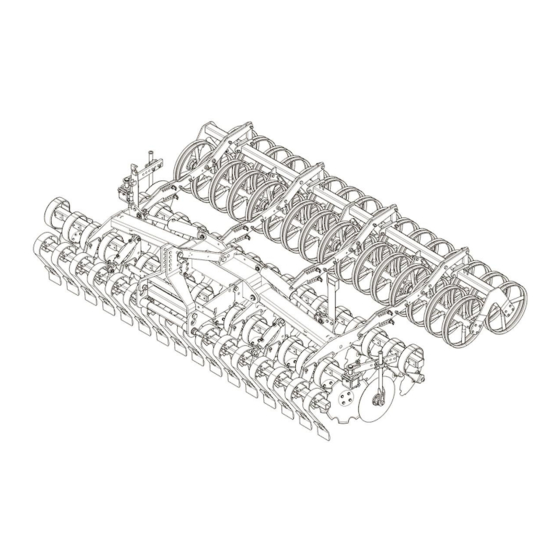
Design and function DESIGN AND FUNCTION Overview 1 Headstock 2 Cross shaft 3 Concave discs 4 Foldable outer concave discs 5 Lateral limiter 6 Working depth adjustment for concave discs 7 Levelling tines 8 Roller 9 Hydraulic transport locking device 10 Lighting equipment (not shown) 11 Additional weights (not shown) 12 Weed harrow (not shown) -
Page 39: Function
Cross shaft L3/Z4 complies with category 4N. The headstock is suitable for attachment to Quick-Hitch couplings. The Heliodor 9 K is available only with a top link pin category 3. 5.2.2 Hollow Discs The implement consists of two rows of curved and notched hollow discs which are arranged separately on the frame via an intermediate frame. -
Page 40: Levelling Tines
Design and function 5.2.6 Levelling tines The levelling tines lightly level the soil and any existing growth. 5.2.7 Rollers The rollers ensure reconsolidation and additional crumbling of the soil. During op- eration on the field they bear the weight of the implement if the implement has been lowered for work and they ensure exact depth guiding. -
Page 41: Preparation Of The Tractor
Preparation of the Tractor PREPARATION OF THE TRACTOR Tyres The pressure - especially in the rear tractor tyres - must be equal. In heavy condi- tions it may be necessary to add wheel weights and/or water ballast. (See manu- facturer’s instructions). Lift Rods Adjust lift rods to equal length. -
Page 42: Hydraulic Equipment Required
Preparation of the Tractor Hydraulic equipment required The implement is supplied as standard with separate connections for each con- sumer. The protecting caps on the hydraulic couplings are coloured and the hyd- raulic couplings themselves are marked alphanumerically. In order to activate the hydraulic devices listed, the tractor must be equipped with the following spool valves: Double- Tractor / implement... - Page 43 (1) and the top link pin (2) must be replaced with a sui- table, authorised version. More information is available in the following table. Heliodor 9 K Cross shaft Category 3N Cross shaft Category 3...
- Page 44 Preparation of the Tractor The table below shows the maximum permissible tractor power and dimensions for each category as per ISO 730-1. Tractor power Cat. Pintle diameter of cross Length of cross shaft shaft (mm) (shoulder distance) (mm) 36.6 36.6 50.8 * The indicated values refer to the design of the cross shaft.
-
Page 45: Hydraulic System
Preparation of the Tractor Hydraulic system 6.7.1 Transport Danger from accidental lowering of the three-point linkage WARNING Accidental lowering of the three-point linkage due to incorrect set- tings or operation can cause accidents and damage the imple- ment, resulting in death or serious injury. ... -
Page 46: Preparations On Implement
Preparations on implement PREPARATIONS ON IMPLEMENT Final assembly For transportation-specific reasons, the implement is not always delivered in a ful- ly-assembled condition. Use the implement only when the implement has been fully assembled and a functional check has been performed. -
Page 47: Attaching The Implement
Attaching the implement ATTACHING THE IMPLEMENT Risk of injury when coupling the device WARNING There is a risk of body parts being crushed between the tractor and device The tractor must be secured against unintentionally rolling away. Never actuate the hydraulic system of the tractor if there are people between the tractor and device. -
Page 48: Attachment
Attaching the implement Danger to life due to unsecured connection between lower link and drawbar If the connection between lower link and drawbar is not secured, the pintle of the drawbar may slip out. DANGER As a result, the implement may fall down and injure or kill people in the immediate vicinity. - Page 49 Attaching the implement Connect the hydraulic hoses to the trac- tor in accordance with the table in the section »Hydraulic equipment required, page 40«. Connect the electrical cables to the trac- tor in accordance with the table in the section »Power sources required, page 39«.
-
Page 50: Drawbar
Attaching the implement Drawbar The drawbar (1) can be mounted on the device at two heights = draw point positi- ons. The picture shows the drawbar (1) in the upper mounting position = low draw point. The bores (2) are used to hold the drawbar (1) in the lower mounting position = high draw point. -
Page 51: Upper Control Link
Attaching the implement Upper control link Risk of injury from unsecured upper control link pin If the upper control link pin is not secured, it may slip out or get CAUTION lost. As a result, the implement may fall down or be damaged. ... -
Page 52: Driving On Public Highways
Driving on public highways DRIVING ON PUBLIC HIGHWAYS General information A proper lighting system, identification and equipment must be on the implement, if it is to be transported on public roads. The country-specific valid laws and regu- lations pertaining to driving on public roads must be observed. Preparation for driving on public roads Before commencing a journey on public roads, the following components and sa- fety equipment must be checked to ensure they are working properly and can be... -
Page 53: Lighting System
Driving on public highways Before driving on public roads, cover the hollow discs (1) of the side sections with the protective devices (2). Fold in the side sections; see "Fold in on page 54". Mount the flat steel bar (3) with the safe guards. -
Page 54: Transport Dimensions
Driving on public highways Transport dimensions Danger if implement is raised too high WARNING The folded implement may be too high to travel on public roads. This poses an increased risk when driving under bridges, entran- ces and high-voltage power lines. ... -
Page 55: Folding The Lateral Sections In And Out
Folding the lateral sections in and out FOLDING THE LATERAL SECTIONS IN AND OUT Risk of accident due to the lateral sections folding in incor- rectly Incorrect folding in of the lateral sections leads to accidents if per- sons are located in the swivelling and folding range of the lateral DANGER sections or if high-voltage lines are located in the swivelling and fol- ding range of the lateral sections. -
Page 56: Fold In
Folding the lateral sections in and out 10.1 Fold in Make sure the weed harrow CANNOT collide with the lighting equipment when folding in. o If necessary, dismantle the lighting equipment before fol- ding in. Before folding in the lateral sections (1), fully lift the machine. -
Page 57: Extending
Folding the lateral sections in and out 10.2 Extending Risk of accident due to incorrect extension of the side sec- tions Incorrect extension of the side sections will result in accidents if there are people in the hazardous areas of the side section or if there are high-voltage lines in the slewing and folding area of the side sections. - Page 58 Folding the lateral sections in and out Remove the protective equipment. Before extending the side sections (1), lift out the implement all the way. Release the control unit of the tractor for the folding cylinders (2). Then switch the control unit to the retract position (1st pressure position) and then quickly to the extend position (2nd pres- sure position).
-
Page 59: Folding The Outer Hollow Discs
Folding the lateral sections in and out 10.3 Folding the outer hollow discs Risk of accidents if outer hollow discs are not folded DANGER The Heliodor 9/700 K is higher than 4 m if the outer hollow discs on the implement are not folded inwards. This may cause accidents when travelling on public roads, result- ing in death or injury. -
Page 60: Unfolding The Outer Hollow Discs
Folding the lateral sections in and out 10.4 Unfolding the outer hollow discs Before working in the field, unfold the outer hollow discs (1) as follows: Release the locking pin (2). Pull the locking pin out of the hole (3). ... -
Page 61: Operation
Operation OPERATION Read and follow the information in the section entitled "Safety and protection measures". CAUTION The implement may only be used, maintained and repaired by people who are familiar with it and who are aware of the ha- zards involved. -
Page 62: Working Depth
Operation 11.1 Working depth The working depth of the implement can be adjusted in the range from approx. 3 cm to 12 cm. Depending on the equipment installed on the implement, the working depth is ad- justed mechanically (by means of a pin) or hydraulically. Risk of accidents due to freely rotating rollers WARNING There is a risk of crushing and trapping body parts when climbing... -
Page 63: Setting The Roller Lowering Depth
Operation Hole 1 => shallowest working depth Hole 12 => deepest working depth Lower the implement into the soil. When the working depth is reached, there is no load on the upper pins (3). Insert the upper pins (3) directly above the carrier (4). -
Page 64: Hydraulic Working Depth Setting
Operation To set the lowering depth: Move the implement into the working position. There is no load on the upper pins (1). Release the pins by pulling the linch pins out of the pins. Pull the pins out of the adjustment plates (2). -
Page 65: Concave Disc Setting In The Tractor Track
Operation 11.2 Concave disc setting in the tractor track The implement can be fitted with adjustab- le concave discs in the area of the tractor tracks. The adjustable concave discs are used to loosen the tracks and optimise le- velling. The concave discs in the tractor track have three different positions: Home position (c): The concave discs in... -
Page 66: Lateral Draw
Operation Ensure that the holes are correctly as- signed: Working Hole Hole in pla- depth spring tines Step 2 Step 1 Home position * Do not use hole d in the plate. 11.3 Lateral draw The front and rear oblique positioned hol- low discs create opposite lateral forces, which are compensated. -
Page 67: Lateral Limiters
Operation 11.4 Lateral limiters Danger from unsecured parts CAUTION If the lateral limiters are not secured during adjustment, they may slip downwards in an uncontrolled manner. This may cause crush injuries to the hands or foot injuries. Secure the lateral limiters. The lateral limiters (1) prevent the rear right hollow disc and the front left hollow disc from leaving furrows or throwing up... - Page 68 Operation Swivelling the lateral limiter outwards: Release the locking pin (1). Pull the locking pin out of the hole (2). Select the hole for the swivel position (3) by swivelling the carrier with the lateral limiter outwards. ...
-
Page 69: Mounting And Dismantling The Weed Harrow
Operation Changing the height and angle of the lateral limiter: Loosen the clamping screws in the clamping fixture (1). Turn the round stalk (2) in the clamping fixture until it is at the required angle. Set the height of the round stalk (2) in the clamping fixture. - Page 70 Operation Mounting the weed harrow The weed harrow (1) must always be mounted on a trailing roller. Brackets (2) and U-bolts (3) are available for mounting. There is one harrow segment for each trai- ling roller segment. Example image Position both U-bolts (3) on the support- ing frame (5) of the roller.
-
Page 71: Adjusting The Weed Harrow
Operation 11.6 Adjusting the weed harrow Adjusting the angle Turn the screw (1) with the spanner Anticlockwise = flat angle Clockwise = steep angle The yoke (2) moves up or down with the harrow tube. The angle of the harrow changes. - Page 72 Operation Swivel the holder (3) to the required height. Example image To fix the holder in the swivelled in positi- Insert the pin (2) into the matching not- ches above and below the holder. Example image Secure the pin with a linch pin (1). ...
-
Page 73: Wheelmark Eradicator
Operation 11.7 Wheelmark eradicator Wheelmark eradicators (1) can be mounted on the carrier (2). The wheelmark eradicators can be relocated at the side and their depth adjusted. 11.7.1 Relocation at the side Adjust the wheelmark eradicator (1) to the bout of the tractor as follows: ... -
Page 74: Adjusting The Working Depth
Operation 11.7.2 Adjusting the working depth The wheelmark eradicators are set to ap- prox. 5 cm deeper than the bout of the tractor. Adjust the working depth of the wheelmark eradicator as follows: Raise the implement to relieve the load- ing on the wheelmark eradicator (1). -
Page 75: Rollers
The implement can be fitted with different types of roller. See the roller table be- low. The rollers control the working depth of the implement. The degree of recon- solidation or crumbling is determined by the type of roller used. Heliodor 9 K Roller type 400 450 500 600 700... -
Page 76: Knife Rollers
Operation 11.8.2 Knife rollers Adjusting the knife roller Blade working depth On both sides of the roller: Take any loads off the upper bolt (4). o Turn the screw (3) clockwise to do so. Release the upper bolt (4). ... - Page 77 Operation the support plate (1). o The knives operate more ag- gressively if the deflection trav- el is short. Large deflection travel (for very light or rocky soils): Insert the lower bolt (5) into the lower holes in the adjustment plate (2). ...
- Page 78 Operation Blade position There are two mounting positions for the blades (11) on the knife bar (8): Front position (9) (standard) Rear position (10) (after wear) After wear: Reposition the blades (11) towards the rear (10).
-
Page 79: Pressure Load On Rollers - Penetration Characteristic
Operation 11.8.3 Pressure load on rollers - penetration characteristic The pressure load on the rollers is determined by the position of the upper link and the mounting position of the drawbar. The hydraulic unit of the three-point linkage on the tractor must be switched to the float position. - Page 80 Operation The lower the upper link is mounted on the implement's three-point tower, the greater the pressure load on the rollers – resulting in excellent penetration charac- teristic. The higher the upper link is mounted on the implement's three-point tower, the lower the pressure load on the rollers –...
- Page 81 Operation The position of the top link (1) can be ad- justed as follows: Lower the implement completely. Switch the hydraulic system for the trac- tor's three-point linkage to position con- trol. Activate the hydraulic system for the tractor's three-point linkage until there is no load on the top link pin (2).
- Page 82 Operation Drawbar mounting position The mounting position of the drawbar (1) with unhitched implement can be changed as follows: Remove the nuts (3) on the bolts (4) of the two locking pieces (5). Pull the drawbar (1) as far as the middle out of the bores of the rail plates (6).
-
Page 83: Additional Weights
Operation Push the locking pieces (5) onto the drawbar (1). Ensure that the side with the support surface (7) is facing the rail plate (6). Push the drawbar (1) through the bores until the two ends of the drawbar (1) on the left and right are the same distance from the rail plates (6). -
Page 84: Turning At The Headland
Operation 11.10 Turning at the headland DANGER Risk of damage to components If the implement is not fully raised, there is a danger that compo- nents may be damaged during an improper turn at the headland. Before turning at the headland the implement must be completely raised before turning-in to avoid any damage to the implement. -
Page 85: Cleaning And Care
Cleaning and care CLEANING AND CARE 12.1 Cleaning with a high-pressure cleaner When cleaning with a high-pressure cleaner, ensure that water does not get into the electrical and electronic components. Do not point the jet of the high-pressure cleaner directly at the bearings. -
Page 86: Detaching The Implement
Detaching the implement DETACHING THE IMPLEMENT Detach the implement on a level, surfaced area. Remove the safety guards. Lift the implement. Unfold the implement. Lower the implement. Both rows of hol- low discs and the roller must be standing on the ground. - Page 87 Detaching the implement Secure the implement to prevent it from rolling away. Disconnect the lower links from the pivots (2) on the cross shaft (1). Drive the tractor 20 to 30 cm away from the implement. Secure the tractor to prevent it from rol- ling away.
-
Page 88: Put The Implement Out Of Operation
Put the implement out of operation PUT THE IMPLEMENT OUT OF OPERATION 14.1 Shutting down the implement in an emergency In an emergency shut down the implement via the tractor. Switch the tractor engine off. Remove the ignition key. Damage caused by improper storage of the implement If incorrectly or improperly stored, the implement may be dam- CAUTION... -
Page 89: Maintenance And Repairs
Maintenance and repairs MAINTENANCE AND REPAIRS 15.1 Special safety instructions 15.1.1 General Risk of injury when carrying out maintenance and repair work There is always the risk of injury when carrying out maintenance and repair work. WARNING Use suitable tools, suitable climbing aids, platforms and support elements. -
Page 90: Immobilise The Implement For Maintenance And Repairs
Maintenance and repairs 15.1.4 Immobilise the implement for maintenance and repairs Risk of accidents when tractor starts up Injuries may occur if the tractor starts moving during maintenance and repair work. Switch off the tractor engine before carrying out any work on the WARNING implement. -
Page 91: Working Under The Raised Device
Maintenance and repairs 15.1.7 Working under the raised device Risk of accident due to lowering and extending of compo- nents and devices It is extremely dangerous to work under raised or next to retracted components and devices. WARNING Always secure the tractor to prevent it from rolling away. ... -
Page 92: Environmental Protection
Maintenance and repairs Risk of accident due to tool slipping off If applying a large force, e.g. when loosening bolts, the tool may WARNING slip off. This may result in hand injuries on sharp-edged parts. Avoid applying a large force by using suitable auxiliary equip- ment (e.g. -
Page 93: Maintenance Intervals
Replace damaged or defective hydraulic hoses im- mediately. The hydraulic hoses must be replaced 6 years after the date of manufacture at the latest. Only used hydraulic hoses approved by Lemken. Check that all safety equipment is functioning pro- Safety equipment perly. -
Page 94: Lubrication Chart
Maintenance and repairs 15.4 Lubrication chart For all lubrication work, always use high-quality Olistamoly 2 grease or an equivalent high-quality grease. Grease nipple Folding joints (a) Pins on the hydraulic rams, folding (b) Pins on the hydraulic rams, levelling tines (c) Pendulum bearing (d) (5 m, 6 m and 7 m only) Other components Grease the pins. -
Page 95: Tightening Torques
Maintenance and repairs 15.5 Tightening torques 15.5.1 General Secure self-locking nuts that have been loosened against working themselves loose again by: Replacing them against new self-locking nuts Using lock washers Using locking compounds such as Loctite The tightening torques set out below refer to screw connections that are not specifically mentioned in these operating instructions. -
Page 96: Checking Connections To The Tractor
Maintenance and repairs 15.6 Checking connections to the tractor 15.6.1 Hydraulic connections Risk of accident due to spraying hydraulic fluid Fluid (hydraulic oil) escaping under high pressure can penetrate WARNING the skin and cause severe injuries. In case of injury, seek medical attention immediately. -
Page 97: Flex Ring Roller Scrapers
Maintenance and repairs 15.7.2 Flex ring roller scrapers The scrapers (1) on the flex ring roller (2) must be replaced when worn down to a thickness of 5 mm so as to prevent the remaining piece from being lost and sub- sequent damage from being incurred. -
Page 98: Technical Data
Technical data TECHNICAL DATA Heliodor 9 K Weight, approx. [kg]* 2357 2474 2606 2968 3410 Length, approx. [cm]* Transport width, approx. [cm] Working width, approx. [cm] Centre of gravity approx. [cm] up to kW (hp) 118 (160) 132 (180) 147 (200) 176 (240) 206 (280) Min. -
Page 99: Noise, Airborne Sound
Noise, Airborne Sound NOISE, AIRBORNE SOUND The noise level of the implement does not exceed 70 dB (A) during work. NOTES As the version of equipment is depending from the order, the equipment of your implement and its description concerned may deviate in some cases. To ensure a continuously updating of the technical features, we reserve the right to modify the design, equipment and technique. -
Page 100: Index
Index INDEX Attachment ......................46 Axle loads ......................27 Detaching ......................84 Drawbar ......................48 Extension ......................55 Folding in ......................54 Folding the outer hollow discs ................57 Hydraulic equipment .................... 40 Hydraulic system ....................43 Knife rollers ......................74 Lateral draw ...................... - Page 101 Index Upper control link ....................49 Warning signs ..................... 17 Weed harrow ....................67, 69 Wheelmark eradicator ..................71...
Need help?
Do you have a question about the Heliodor 9 K and is the answer not in the manual?
Questions and answers