Table of Contents
Advertisement
Quick Links
Instruction book
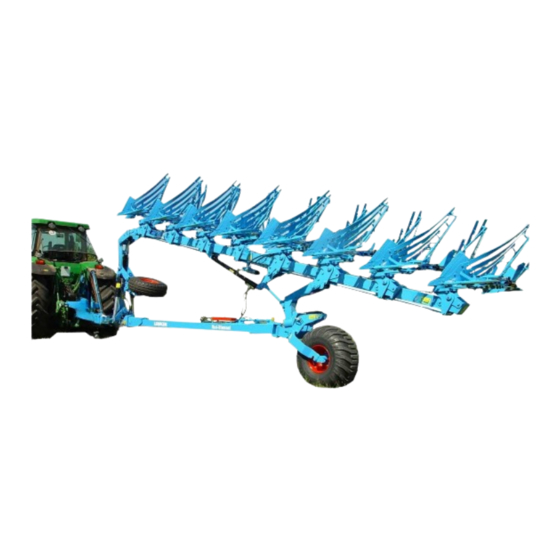
Semi-mounted reversible ploughs
EuroDiamant
10, 10 X, 10 OF, 10 X OF
and
VariDiamant
10, 10 X, 10 OF, 10 X OF
- EN -
Safety is our concern
.
Part No
: 175 3604
EN-3/10.09
LEMKEN GmbH & Co. KG
Weseler Straße 5, D-46519 Alpen / Postfach 11 60, D-46515 Alpen
Telefon (0 28 02) 81-0, Telefax (0 28 02) 81-220
eMail: lemken@lemken.com, Internet: http://www.lemken.com
Advertisement
Table of Contents

Related Manuals for LEMKEN EuroDiamant 10


Summary of Contents for LEMKEN EuroDiamant 10
- Page 1 Safety is our concern Part No : 175 3604 EN-3/10.09 LEMKEN GmbH & Co. KG Weseler Straße 5, D-46519 Alpen / Postfach 11 60, D-46515 Alpen Telefon (0 28 02) 81-0, Telefax (0 28 02) 81-220 eMail: lemken@lemken.com, Internet: http://www.lemken.com...
- Page 3 Only use genuine Lemken spare-parts. Spurious parts negatively influence the function of the implement, show a shorter lifetime and increase in nearly all cases additional maintenance. We trust that you will understand that LEMKEN is unable to guarantee poor operation and damage caused by using spurious parts!
- Page 4 Under „defined use“ the manufacturer’s prescribed operation-, maintenance- and repair conditions are to be adhered to! • The LEMKEN SMV 9 may only be operated, maintained and repaired by such persons who have been made acquainted with it and who have been advised about the dangers! •...
-
Page 5: Table Of Contents
CONTENTS 1 SAFETY TECHNICAL ADVICE ............... 5 2 WARNING STICKERS..................8 General Instructions................8 Meaning of the stickers................8 Position of warning stickers..............10 3 PREPARATION OF TRACTOR ..............11 Tyres...................... 11 Lift Rods....................11 Check Chains or Sway Blocks............. 11 Hydraulics ..................... - Page 6 Distance between the tractor and the furrow edge (with onland- version, only) ..................25 10 SHEARBOLTS .................... 26 11 OVERLOAD SAFETY DEVICES..............27 11.1 Mechanical, automatic Non-Stop TANDEM overload safety device . 27 11.2 Hydraulic NON-STOP TANDEM overload safety device “HydriX”..27 11.2.1 Adjusting the operation pressure ............
-
Page 7: Safety Technical Advice
1 SAFETY TECHNICAL ADVICE • Read and adhere to these „General Health- and Safety precautions“ before putting the plough to work! • The fitted warning- and advising plates give important hints for riskfree operation. Following these helps your own safety! •... - Page 8 implement remove cable from the generator and the battery! • Before working on the electric gear disconnect battery cables! Attachment of the implement • When fitting the machine to the three-point linkage of the tractor bring all control levers into such a position that unintentional lifting or lowering is impossible! •...
- Page 9 Tyres • When working on the tyres make sure that the implement has been placed on the ground safely and that it is secured by chocks against unintentional rolling! • Fitting tyres requires knowledge and special tools! • Repairwork on tyres may only be conducted by trained staff and with suitable tools! •...
-
Page 10: Warning Stickers
2 WARNING STICKERS 2.1 General Instructions The LEMKEN semi-mounted reversible ploughs are equipped with all features to ensure safe operation. Where potential danger areas of the implement can not be fully safeguarded, warning stickers are fitted which draw attention to these. - Page 11 WARNING: Hydraulic accumulator contains gas and oil under pressure. For removal and repair instructions in technical manual must be followed. WARNING: Keep well clear of the working and swinging area of the implement! WARNING: Keep well clear of the turning and swinging area of the implement! WARNING: Pinch point!
-
Page 12: Position Of Warning Stickers
2.3 Position of warning stickers... -
Page 13: Preparation Of Tractor
3 PREPARATION OF TRACTOR 3.1 Tyres Ensure that all are at the manufacturer's recommended pressures, that left and right hand side tyre pressures are identical and state of wear is approximately the same. For heavy conditions it may be necessary to add wheel weights and/or water ballast. - Page 14 3.6 Overall width of tractor Tractors with an overall width of up to 300 cm can be turned-in at 90° to the implement. Tractors with an overall width greater than 300 cm can only be turned-in to the implement to a specific degree. Caution! In each case, turn-in the tractor no further than it takes to ensure that the tractor’s tyres never come into contact with the plough’s components at any time.
-
Page 15: Attaching And Detaching The Plough
4 ATTACHING AND DETACHING THE PLOUGH 4.1 Attaching to the Tractor Attach the plough which must be parked in right-handed working position as follows: • Set tractor hydraulics 'Position Control'. • Attach lower links to the drawbar (13) and secure. •... - Page 16 • Fit warning boards lighting equipment, if the plough has to be transported on public roads. • For transport the plough frame must be turned in halfturned position! • After that the lock valves (SP) of both rams (21) must be locked! Warning: After attaching it must be checked whether, with fully lifted...
-
Page 17: Stand
4.2 Stand The two-piece stand (14) must be fit together in length so that the drawbar (13) is parallel to the ground when the plough is parked in working position. Therefore plough must first attached to the tractor and after that the headstock (7) –... -
Page 18: Detaching From The Tractor
4.3 Detaching from the Tractor The plough must always be parked in right-handed working position and on level and firm ground. Before the first detaching the length of the two-piece stand (14) must be adapted according to section “Stand”. • Set tractor hydraulics to 'Position Control'. -
Page 19: Turning Of The Plough Frame
5 TURNING OF THE PLOUGH FRAME Turn the plough frame, only, with plough attached to the tractor. The hydraulic rams (21) of the turnover mechanism must be connected to a separate double acting spool valve via its hydraulic hoses. To turn and to reverse the plough, operate as follows: •... -
Page 20: Of-Swinging Device (With Onland-Verion, Only)
6 OF-SWINGING DEVICE (WITH ONLAND-VERION, ONLY) Via the OF-swinging device (OF) the semi-mounted reversible plough can be converted from “onland” operation to “in the furrow” operation. Before conversion the plough frame must be set to working position. 6.1 Conversion from “in the furrow” to “onland” operation •... -
Page 21: Conversion From "Onland" To "In The Furrow" Operation
6.2 Conversion from ”onland“ to ”in the furrow“ operation • Close lock valves (SP) of the turnover ram (21). • Open lock valves (HS) of the hydraulic ram (ZY). • Lift plough frame in front and the rear a little, so that the plough bodies do not touch the ground. -
Page 22: Transport
7 TRANSPORT For transport turn the attached plough into the half-turned position and lock the turnover-mechanism by closing both lock- valves (SP). (Fit marker boards and lighting equipment when using public roads.) Lift the plough in front (with tractor power lift) until there is sufficient clearance between plough and ground and lower the plough in the rear (with hydraulic ram of the... -
Page 23: Turning On Headlands
8 TURNING ON HEADLANDS The width of the headlands should be between 16 m and 22 m. It depends on the manoeuvrability of the tractor, the length of the plough and the field conditions. When reaching the headlands, the tractor will be steered to the ploughed side and the turnover operation will be started by setting the spool valve lever of the turnover device... -
Page 24: Adjustments
9 ADJUSTMENTS 9.1 Front furrow width The front furrow width will be adjusted by means of the turnbuckle (19) or a hydraulic ram. • Turnbuckle longer = wider front furrow • Turnbuckle shorter = narrower front furrow Instead of the turnbuckle (19) a double acting hydraulic ram can be used, thus the front furrow width can be adjusted from the tractor seat. -
Page 25: Angle Adjustment
9.3 Angle adjustment With the plough in work at its required depth, the legs should be approx. vertical when viewed from the rear. This adjustment is achieved by use of the vertical adjuster screws (20). Adjust the angle at follows: Raise the front of the plough a little and lower it again to unload the adjuster screw (20) -
Page 26: Working Width Per Body (Varidiamant)
9.4.2 Working width per body (VariDiamant) The working width of the VariDiamant plough is variably adjustable by means of the hydraulic ram (23) and that from 30 cm up to 55 cm per body. Narrower working width per furrow - close the ram (23) Wider working width per furrow - open the ram (23) 9.5 Side pull alignment... -
Page 27: Pull Point Height (With Onland-Version, Only)
9.6 Pull point height (with Onland-version, only) Especially in connection with crawlers it is important that the crawler shows the same soil pressure over the complete length during work. Therefore the pull point (Z) of the semi-mounted ploughs has to be adapted in height. -
Page 28: Shearbolts
M14x70LS51x15-10.9 301 4606 M20x80LS50xB25-10.9 EuroDiamant 10 301 3992 M16x100LS70x25-8.8 301 4661 M24x100LS70x25-10.9 EuroDiamant 10 X 301 3595 M14x70LS51x15-10.9 301 4606 M20x80LS50xB25-10.9 • In the shearing area are pinch points. Keep distance! • Sitting or standing on the implement during operation is not permissible! •... -
Page 29: Overload Safety Devices
11 OVERLOAD SAFETY DEVICES 11.1 Mechanical, automatic Non-Stop TANDEM overload safety device The automatic overload safety device protects the plough from damage when obstacle encountered. mechanism breaks back upon impact and automatically returns the body to the working position once the obstacle has been passed. -
Page 30: Adjusting The Operation Pressure
11.2.1 Adjusting the operation pressure After connecting the adjusting valve unit to the tractor spool valve, the system is operable with maximum minimum operation pressures adjusted by the factory. If required the operation pressure can be adapted individually. For that adjustment the knobs (H) and (T) are used. -
Page 31: Make Hydraulic System Pressureless
The maximum operation pressure will be reached by means of pressurising connection A of the adjusting valve unit for a few seconds. The minimum operation pressure will be reached by means of pressurising connection B of the adjusting valve unit for a few seconds. Intermediate operating pressure values can be adjusted by means of shortly operation of the spool valve in the first or second pressure... -
Page 32: Lateral Overload Safety Device (Only With Varidiamant 10 X)
11.3 Lateral overload safety device (only with VariDiamant 10 X) The lateral overload safety device with spring packages (FP) is an additional overload safety device, which ensures beside the standard large lateral tripping of the bodies, an additional safety for the beams and legs. Via a linkage (LG) the steering rod (ST) fort he bodies will be adjusted respectively fixed. -
Page 33: Depth Control Wheel
EPTH CONTROL WHEEL The depth control wheel (SV) is standard equipment with semi-mounted reversible ploughs in onland-version. During turnover procedure the wheel swings away from the stop and over to the opposite working position. Via a spring (RF) the depth control wheel will be moved in working position against the stop (GA). -
Page 34: Bodies
14 BODIES 14.1 Penetration angle To check correct pitch, measure from plough frame to underside of new point and end of landslide. Frame to point measurement (D) should be 1,5 cm (5/8 in) greater than frame to landslide. I e: Measurement D should be + 1,5 cm from parallel to frame. -
Page 35: Skim Coulters
15 SKIM COULTERS 15.1 General instructions The skim coulters (65) should be finally set when the plough is operating at the required depth and speed. The skim point should be set to a depth between 5 and 10 cm (2 - 4 in) and the tip of the point set to run 2 - 3 cm (3/4 - 1 1/4 in) to the landslide of the body. -
Page 36: Trashboards
16 TRASHBOARDS Bolt carrier (78) of the trashboard (77) to the holes provided in the top of the mouldboard. Fit trashboard (79) to the carrier and adjust for optimum trash 'mix'. Adjust support-bolt (80) so that it touches the leg. Secure bolt (80) by means of locknut (81). -
Page 37: Coulters
17 COULTERS 17.1 Sword Coulters Sword coulters (83) are available. They are recommended tough heavy conditions and provide a clean cut of a furrow wall. It is recommendable to provide - at least - the rear bodies with a coulter. 17.2 Disc coulters When fitted, disc coulters (93) should be set to a working depth of 7 - 9 cm (2 3/4 - 3 1/2... - Page 38 If it is required to remove the disc coulter, a distance bush must be fitted instead of the stalk (F) to enable a sealing and a greasing of the lubrication bore of the groove nut (NM). The screw (AS) with grease nipple may only be fitted with stalk (F) or distance bush.
-
Page 39: Wide Furrow Cutters
18 WIDE FURROW CUTTERS If the tractor is equipped with wide tyres, it is recommendable to use wide furrow cutters (BFM). The wide furrow cutters must be fitted to the landslide of each rear body. If the plough is equipped with C-bodies, to each rear body the landslide 340 1450 must be fitted so that the holders (HL) and (HR) of the wide furrow cutter can be fitted. -
Page 40: Subsoilers
19 SUBSOILERS The bracket of the subsoiler UD6 will be fitted as shown in the sketch. By means of displacing the stalk (102) the working depth of the subsoiler can be adjusted. Maximum working depth = 20 cm Minimum working depth = 14 cm After the adjustment fit pin (104) and secure. -
Page 41: Maintenance
20 MAINTENANCE The semi-mounted reversible ploughs require a little maintenance, only. All pivot points must be greased regularly with environmentally friendly grease according to the following table. For a long operation break all smooth areas of wearing parts, pins and adjusting devices must be greased. Before and after a long working hours... - Page 42 IMPORTANT: Do not clean this implement with a Pressure Washer during the first 6 weeks. After this time a minimum nozzle distance of 60 cm must be observed with a maximum 100 bar and 50 ° C tem- perature! Grease bearing housing of the pin (LB) via the grease-pipe (SL).
-
Page 43: Transport On Public Roads
EuroDiamant 10 8 L 100 from 140/190 264-400 3.300 EuroDiamant 10 8+1 L 100 from 140/190 297-450 3.550 EuroDiamant 10 X 5 L 100 155/210 165-250 2.900 EuroDiamant 10 X 5+1 LN 100 177/240 198-300 3.210 EuroDiamant 10 X 6 L 100... -
Page 44: Noise, Airborne Sound
23 NOISE, AIRBORNE SOUND The noise level of the SMV and SMVX ploughs does not exceed 70 dB (A) during work. 24 NOTES It must be stated that these instructions apply only to the current design. 25 PRODUCT REGISTRATION / GUARANTEE We would like to point out that the guarantee period starts, only when the completely filled-in and signed product registration has been returned to us.
Need help?
Do you have a question about the EuroDiamant 10 and is the answer not in the manual?
Questions and answers