
Related Manuals for LEMKEN Rubin 12 KUA


Summary of Contents for LEMKEN Rubin 12 KUA
- Page 1 Operating Instructions Compact Disc Harrow Rubin 12 KUA - en - Item no. 17510731 06/09.21 LEMKEN GmbH & Co. KG Weseler Straße 5, 46519 Alpen / Germany Telephone +49 28 02 81 0, Fax +49 28 02 81 220 lemken@lemken.com, www.LEMKEN.com...
- Page 3 However, this brief instruction is not a substitute for thorough study of the operating instructions. These operating instructions will help to familiarise you with the LEMKEN GmbH & Co. KG device and the options available for using it.
- Page 4 Remember that you should only use genuine LEMKEN spare parts. Reproduction parts have a negative influence on the function of the device, have a shorter ser- vice life and present risks and hazards that cannot be estimated by LEMKEN GmbH & Co. KG. They also increase the maintenance costs.
-
Page 5: Table Of Contents
CONTENTS General information ....................10 Liability ......................... 10 Guarantee ........................10 Copyright ........................11 Optional accessories ....................11 Type plate ........................12 Symbols used in the Operating Instructions ............14 Hazard classes ......................14 Information........................14 Environmental protection ................... 14 Indication of passages .................... - Page 6 Applicable rules and regulations ................28 Operation on public highways ................... 28 3.9.1 Lighting system and identification ................28 3.9.2 Requirements of the tractor ..................28 3.9.3 Permitted transport speed ..................29 3.9.4 Check before departure ..................... 29 3.9.5 Correct behaviour in road traffic ................30 3.10 Obligation of the operator ..................
- Page 7 Hydraulic equipment required ..................41 Brake system ....................... 42 6.6.1 Air brake system ......................42 6.6.2 Hydraulic brake system ..................... 42 6.6.3 Without brake system ....................42 Three-point linkage ..................... 43 Traction device ......................44 Hydraulic system ......................44 6.9.1 Transport ........................44 6.9.2 Field work ........................
- Page 8 10.7 Safety guards ....................... 72 10.8 Lighting equipment and signs ................... 73 10.8.1 General ........................73 10.8.2 Lighting equipment ....................73 10.8.3 Testing the lighting equipment ................74 10.8.4 Signs ........................74 10.9 Levelling harrow ......................75 10.10 Wheelmark eradicators ....................75 10.11 Outer concave discs ....................
- Page 9 11.13 Pressure load on the rollers ..................93 11.13.1 General ....................... 93 11.13.2 Pressure load on packer profile roller and packer double roller ......93 11.14 Turning at the headland ....................94 11.14.1 Implement with lower link connection ..............94 11.14.2 Implement with hydraulic drawbar ...............
- Page 10 16.2 Environmental protection ..................112 16.3 Lubrication ......................... 112 16.4 Maintenance intervals ....................113 16.4.1 After the initial start-up (at the latest after 2 hours) ..........113 16.4.2 Daily inspection ....................113 16.4.3 Weekly check ....................... 114 16.4.4 Annual check ......................114 16.4.5 Lubrication schedule ....................
- Page 11 17 Technical data ....................... 129 17.1 Dimensions ........................ 129 17.2 Weights ........................129 17.3 Permissible masses and loads ................129 17.4 Required drawbar load ..................... 129 17.5 Tractor power ......................129 17.6 Wheels and tyres ...................... 130 18 Noise, Airborne Sound ..................131 19 Notes ........................
-
Page 12: General Information
Co. KG, in particular Section IX, shall apply. Liability. In line with the dimensions cited in these conditions the LEMKEN GmbH & Co. KG shall not be held liable for any personal or material damage, when such damage is caused by one or more of the following reasons: ... -
Page 13: Copyright
Infringements will result in a claim for damages. Optional accessories LEMKEN implements may be equipped with various accessories. The operating instructions below describe both series components and optional accessories. Please note: These accessories will vary depending on the type of equipment. -
Page 14: Type Plate
General information Type plate The implement is marked with a type plate. The type plate is located at the front right of the implement. The operating instructions can apply to va- rious implement types implement equipment. In the operating instructions, contents are marked that are only valid for a certain im- plement type... - Page 15 General information 1 Series 2 Type designation 3 Model year 4 Serial number 5 Year of manufacture 6 Vehicle class, subclass, speed index 7 EU type approval number 8 Vehicle identification number. The vehicle identification number is also engraved in the frame near the type plate. 9 Permitted gross weight [kg]* 10 Permissible drawbar load [kg] (axle 0) 11 Permissible axle load [kg] (axle 1)
-
Page 16: Symbols Used In The Operating Instructions
Symbols used in the Operating Instructions SYMBOLS USED IN THE OPERATING INSTRUCTIONS Hazard classes The following symbols are used in the Operating Instructions for particularly im- portant information: DANGER Denotes an imminent hazard with high risk, which will result in death or severe physical injury, if not avoided. -
Page 17: Indication Of Passages
Symbols used in the Operating Instructions Indication of passages The following symbols are used for particular passages in the operating instruc- tions: Indicates work steps Indicates enumerations... -
Page 18: Safety Measures And Precautions
Safety measures and precautions SAFETY MEASURES AND PRECAUTIONS General safety instructions for the operator are specified in the chapter entitled «Safety measures and precautions». At the start of some main chapters the safety instructions, which refer to all work to be carried out in this chapter, are listed to- gether. -
Page 19: Safety Features Of The Device
Safety measures and precautions Safety features of the device To protect the operator and the device, the device is equipped with special safety features in accordance with country specific requirements. Always keep all safety devices in working order. Lighting equipment and warning board for the rear and front Warning board for slow moving vehicles (depending Lateral safety guards on national regulations) - Page 20 Safety measures and precautions Safety chain Wheel chocks Hydraulic transport locking device Protection against unauthorised use: Cross shaft Protection against unauthorised use: Drawbar eye Protection against unauthorised use: K80...
-
Page 21: Safety And Warning Signs
Safety measures and precautions Safety and warning signs 3.4.1 General information The implement features all equipment which ensures safe operation. If hazardous areas could not be completely secured with respect to operational safety, warning signs are affixed which indicate these resi- dual risks. -
Page 22: Meaning Of Warning Signs
Safety measures and precautions 3.4.3 Meaning of warning signs Please familiarise yourself with the meaning of the warning signs. The following explanations provide detailed information. Please read and observe the operating in- structions and safety instructions before starting up the implement for the first time. Before carrying out maintenance or repair work, switch off the engine and remove key. - Page 23 Safety measures and precautions Before uncoupling or parking the imple- ment, secure it with wheel chocks. Do not remain in the operating and swivel area of the implement. Danger of crushing. Keep out of the folding area of the device. Keep a sufficient distance away from elec- tric high-voltage lines.
-
Page 24: Meaning Of Other Symbols
Safety measures and precautions 3.4.4 Meaning of other symbols. Sling points Positioning points for jack Lock the lifting device Close the stopcock for the hydraulic cyl- inder before taking the implement on public roads. Open the stopcock for the hydraulic cyl- inder before operating the implement on the field. -
Page 25: Special Safety Instructions
Safety measures and precautions Hydraulic depth adjustment scale 1 Road transport 2 Red indicator (working depth) 3 Blue indicator (hydraulic drawbar posi- tion) Special safety instructions Risk of injury due to non-observance of the currently valid occupational safety guidelines If the currently valid occupational safety guidelines are bypassed WARNING or safety equipment is rendered unusable when handling the de- vice, there is a risk of injury. -
Page 26: Danger Areas
Safety measures and precautions Risk of injury when freeing casualties When rescuing people trapped or injured by the device, there is a risk of additional serious injury to the casualty if the hydraulic con- nections were not connected according to their colour coding as described in the section entitled "Required hydraulic equipment". -
Page 27: Danger Areas When Folding And Unfolding
Safety measures and precautions 3.6.2 Danger areas when folding and unfolding Risk of impact and crushing from moving implement compo- nents There is a risk of impact or crush injuries from moving implement components. The danger area includes the area extending across the entire width of the implement (a). -
Page 28: Residual Risks
Safety measures and precautions Residual risks Residual risks are particular hazards which occur when handling the device and which cannot be eliminated despite a design in accordance with safety require- ments. Residual risks are not usually obvious and may be the source of a potential injury or health hazard. -
Page 29: Hazards Of Hydraulic Systems
Safety measures and precautions Risk of accidents due to freely rotating rollers WARNING If you climb onto freely rotating rollers, there is a risk of crushing or trapping the feet and legs between freely rotating rollers and fixed parts of the implement. ... -
Page 30: Applicable Rules And Regulations
Safety measures and precautions Applicable rules and regulations The applicable rules which must be observed during operation of the device are listed below: Observe the currently valid national highway code! Observe the currently valid national laws and regulations for occupational safety. ... -
Page 31: Permitted Transport Speed
Safety measures and precautions 3.9.3 Permitted transport speed The following table shows the permitted transport speeds depending on the equipment of the implement. Also comply with respective applicable country- specific Road Traffic Act. Equipment Maximum permitted transport speed 25 km/h 40 km/h Without braking system With air brake system... -
Page 32: Correct Behaviour In Road Traffic
Safety measures and precautions 3.9.5 Correct behaviour in road traffic When driving on public highways, observe the relevant statutory national regu- lations. Driving behaviour, steering and braking performance are influenced by ballast weights. Ensure that the tractor has adequate steering and braking performance. ... -
Page 33: Safe Use Of The Implement
Safety measures and precautions 3.11 Safe use of the implement 3.11.1 General Before starting work, familiarise yourself with all the equipment and controls and how they work. Do not operate the implement unless all the safety guards are in place and cor- rectly positioned. -
Page 34: Personnel Selection And Qualifications
Safety measures and precautions 3.11.2 Personnel selection and qualifications The tractor driver must have the appropriate driving licence. All work on the implement must be carried out by properly trained and instructed personnel. The personnel must not be under the influence of drugs, alcohol or medication. -
Page 35: Handing Over The Implement
Handing over the Implement HANDING OVER THE IMPLEMENT As soon as the implement is delivered, ensure that it corresponds with the order package. Also check the type and completeness of any supplied accessories. When the device is handed over, your dealer will explain how it works. ... -
Page 36: Layout And Description
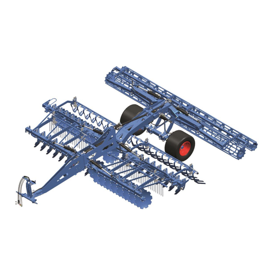
Layout and description LAYOUT AND DESCRIPTION The following assembly groups may be installed on the imple- ment, depending on implement model and national requirements. Overview Headstock Hydraulic working depth adjustment Concave discs Chassis Rebound harrows Rollers Lighting system – not shown Levelling harrows Hydraulic drawbar –... -
Page 37: Function
Layout and description Function 5.2.1 Lower link connection The lower link connection corresponds optionally to category 3N, 3 or 4N accord- ing to ISO 730. Cross shaft L2/Z3 complies with category 3N. Cross shaft L3/Z3 complies with category 3. Cross shaft L3/Z4 complies with category 4N. 5.2.2 Concave discs The implement consists of two rows of curved, serrated concave discs, which are separately attached to the frame. -
Page 38: Hydraulic Transportation Lock
Layout and description 5.2.5 Hydraulic transportation lock In the folded in transportation position the hydraulic transportation lock prevents the side parts of the device from unintentionally folding out. 5.2.6 Lighting system The lighting system contributes significantly to increasing the safety of the imple- ment in road traffic. -
Page 39: Compressed Air Brake
Layout and description 5.2.11 Compressed air brake Overview Compressed air tank Drain valve Double release valve – mano- euvring valve Double release valve – park valve Brake force regulator... - Page 40 Layout and description Brake cylinder Brake lever Guiding screw Holder for guiding screw Brake lever Function description Parking brake Only when the guiding screw (8) has been removed and placed and secured in the holder (9), is the parking brake ready for operation.
-
Page 41: Hydraulic Braking System
Layout and description 5.2.12 Hydraulic braking system The hydraulic braking system is made up of the following components: Service brake Parking brake Shear brake Service brake The tractor's brake valve is used to operate the service brake hydraulically. Brake lever Compression spring for parking brake and rapid emergency brake... -
Page 42: Preparations On Tractor
Preparations on tractor PREPARATIONS ON TRACTOR Tyres The air pressure must be identical, particularly on the rear tractor tyres. Under dif- ficult conditions, additional wheel weights should be used or the tyres topped up evenly with water. Refer to the operating instructions from the tractor manufactu- rer. -
Page 43: Hydraulic Equipment Required
Preparations on tractor The tractor must have the power sources listed below to supply the electrical loads on the implement: Load Volt Direct connection Power socket to the tractor bat- tery Lighting equipment acc. to DIN ISO 1724 Lighting equipment acc. -
Page 44: Brake System
Preparations on tractor Brake system Danger through incompatibility of braking systems The braking system of the tractor and implement must be compat- ible and fully functional. If there is no conformity or if a malfunction exists, sufficient braking deceleration will not be possible. This DANGER means that the tractor and implement may be damaged. -
Page 45: Three-Point Linkage
Preparations on tractor Three-point linkage Loss of the machine WARNING The tractor's three-point linkage category and the category of the cross shaft must match. Otherwise, the cross shaft may slip out of the linkage when driving over uneven ground or due to vibrations. ... -
Page 46: Traction Device
Preparations on tractor Traction device In order to attach the implement, the tractor must have a double-lashing drawbar, a piton fix or a ball head coupling, depending on the design of the traction device. As a minimum, these must be approved for the upward and downward drawbar loads that are listed in the drawbar load table according to equipment and working width, see »Technical data, page 129«. -
Page 47: Attaching And Detaching The Implement
Preparations on tractor 6.9.3 Attaching and detaching the implement Lowering or raising the three-point linkage CAUTION Incorrect settings or operation may result in uncontrolled move- ment of the three-point linkage, causing injuries to the operator. When attaching or detaching the implement, the hydraulic sys- tem for the tractor's three-point linkage must be switched to po- sition control. -
Page 48: Preparations On Implement
Preparations on implement PREPARATIONS ON IMPLEMENT Final assembly For transportation-specific reasons, the implement is not always delivered in a ful- ly-assembled condition. Use the implement only when the implement has been fully assembled and a functional check has been performed. Implements with an air brake system Risk of accidents due to deactivated brakes DANGER... - Page 49 Preparations on implement Place the sliding bolt (1) in the holder (5) on the brake cylinder (3). Secure the sliding bolt (1) with a peg and a nut.
-
Page 50: Attaching The Implement
Attaching the implement ATTACHING THE IMPLEMENT Risk of injury when attaching the implement There is a risk of crushing body parts between the tractor and im- WARNING plement. The tractor and implement must be secured so that they do not accidentally roll away, otherwise crush injuries may occur. - Page 51 Attaching the implement Risk of accidents due to insufficient braking deceleration If there is insufficient braking deceleration the tractor and imple- ment combination may not slow down, or may not slow down quickly enough. This may result in rear-end collisions and cause DANGER death or injury to the driver or other road users.
-
Page 52: Implement With Three-Point Connection
Attaching the implement Implement with three-point connection Risk of accident from implement falling If the lifting rods of the three-point linkage are not locked, the WARNING spherical bearing cannot prevent the implement from overturning in borderline situations. Set lifting rods of the three-point linkage to the same length. ... - Page 53 Attaching the implement Secure cross shaft in the lower links. o Follow the operating instruc- tions of the tractor. Loosen top link pin (3) on the spherical bearing (4): To do this, slightly lift the lo- wer link. ...
- Page 54 Attaching the implement Connect brake hoses (8). Lift implement until the stand (9) no lon- ger touches the ground. Unlock pin on the stand. Pull out the pin. Swivel stand upwards. Fix stand with pin (10). ...
- Page 55 Attaching the implement Implement with compressed air brake system Release the parking brake by activating the red button (3b). Check adjustment of the brake force re- gulator. Implement with hydraulic braking system Release the parking brake: Close the brake valve (3). ...
-
Page 56: Implement With Hydraulic Drawbar
Attaching the implement Observe the following dimensions for the transport position: Coupling height of the drawbar eye or 400 mm – 850 mm the ball-shaped coupling K80 150 mm – 500 mm Ground clearance Maximum permissible transport height 4000 mm Implement with hydraulic drawbar Risk of accident due to tractor drawbar which is too weak or unsuitable... - Page 57 Attaching the implement Connect hydraulic hoses to the tractor according to the section «Required hyd- raulic equipment», page 41. For attachment with drawbar eye: Adjust the height of the drawbar eye (1) via the hydraulic ram of the drawbar. The drawbar eye and the double lashing tractor drawbar must be set to the same height.
- Page 58 Attaching the implement All implements: Depressurise additional spool valves. Connect remaining hydraulic hoses (7) to tractor. o Make certain they are assigned correctly. o Note the hydraulic system la- bels. Connect the electrical connections to the tractor. See »Required power sources, page 40«.
- Page 59 Attaching the implement If necessary, remove the wheel chocks (12) from the wheels and insert into the holder (13). Implement with compressed air brake system Release the parking brake by activating the red button (3b). Implement with hydraulic braking sys- Release the parking brake: ...
- Page 60 Attaching the implement Preparing transportation: Lift implement at front and rear. Fold in lateral parts. See »Folding, page 61«. Lock tractor control units. At the trailer: Close shut-off valve (17) of the hydraulic ram (18). If transportation is on public highways: ...
- Page 61 Attaching the implement The safety chain must be attached such that: the implement cannot drop onto the ground when it is released from the trac- tor. the steering angle of the implement is not restricted. the safety chain does not sag any more than necessary.
- Page 62 Attaching the implement Push the pin (1) inwards. Push the lock (2) towards the hook (3). Check that the safety chain has been attached correctly and that the hook is correctly locked.
-
Page 63: Folding And Unfolding The Side Sections
Folding and unfolding the side sections FOLDING AND UNFOLDING THE SIDE SECTIONS WARNING Tipping hazard Folding and unfolding the implement on steep lateral inclines may cause it to tip. Only fold the side sections in and out on level surfaces. Folding Risk of accidents due to incorrect folding of the side sections Incorrect folding of the side sections can cause accidents if:... - Page 64 Folding and unfolding the side sections Risk of accidents due to unsecured side sections Driving when the tractor spool valves have not been secured can result in accidental unfolding of the side sections during transport if the side sections have not been locked in place by the hydraulic DANGER transport locking device.
-
Page 65: Unfolding
Folding and unfolding the side sections Check that: the hooks (4) on the hydraulic transport locking device (3) are locked in place correctly the hydraulic cylinders (5) are fully ex- tended (approx. 2 cm). Lock the tractor spool valve for the fol- ding cylinders (2) to prevent the side sections from unfolding accidentally. - Page 66 Folding and unfolding the side sections Remove the safety guards. Before extending the side sections, completely lift out the implement at the front and rear. Unlock the tractor spool valve for the fol- ding cylinders (2). Switch the spool valve to the fold positi- on (1st pressure position) and then im- mediately afterwards to the unfold posi- tion (2nd pressure position).
-
Page 67: Fold In Outer Concave Discs
Folding and unfolding the side sections Fold in outer concave discs Risk of accident if outer concave discs are not folded in DANGER The implement is taller than 4 m if the outer concave discs are not folded in. This can cause accidents during road transport, which may result in injury or even death. -
Page 68: Fold Out Outer Concave Discs
Folding and unfolding the side sections Fold out outer concave discs Fold the outer concave discs out for field work as follows: Raise the implement 20 cm. Unlock and remove the locking pin (2). Manually pivot the console with the outer concave disc (1) out towards the rear. -
Page 69: Driving On Public Highways
Driving on public highways DRIVING ON PUBLIC HIGHWAYS 10.1 General information A proper lighting system, identification and equipment must be on the implement, if it is to be transported on public roads. The country-specific valid laws and regu- lations pertaining to driving on public roads must be observed. 10.2 Preparation for driving on public roads Before commencing a journey on public roads, the following components and sa-... -
Page 70: Working Depth Indicator
Driving on public highways 10.4 Working depth indicator Set the working depth of the implement (2 - red pointer) to the “Transport” positi- on (1). Working depth indicator – implements with hydraulic drawbar Set the working depth of the implement (2 - red pointer) to the “Transport”... -
Page 71: Shut-Off Valves
Driving on public highways 10.5 Shut-off valves The shut-off valves on the chassis must be locked when the implement is in the transport position. See »Attaching , page 48«. 10.6 Setting the brake force regulator (Only required for machines with compressed air brake.) Prior to operating the machine ... - Page 72 Driving on public highways Machines with 4 m and 5 m working width Determining axle load by weighing Adjust brake force regulator according to the determined axle load. Actual axle load [kg] Rolling circumference of Adjustment tyres [3092 mm to 3254 From 1 (locked) 1 (locked)
- Page 73 Driving on public highways Machines with 6 m and 7 m working width Determining axle load by weighing Adjust brake force regulator according to the determined axle load. Actual axle load [kg] Rolling circumference of Adjustment tyres [3092 mm to 3254 From 1 (locked) 1 (locked)
-
Page 74: Safety Guards
Driving on public highways 10.7 Safety guards Risk of injury from hollow discs or harrow tines WARNING Other road users may be injured by the hollow discs or harrow ti- nes. Always fit the safety guards before travelling on public roads. Risk of injury due to the weight of the safety guard WARNING The weight of the safety guard poses a risk of injuries to the... -
Page 75: Lighting Equipment And Signs
Driving on public highways Push the safety guard (2) and its bracket (3) into the relevant holder (4). Hook the tensioning strap into the safety guard. Attach the other end of the tensioning strap to the holder (4) using the hook. 10.8 Lighting equipment and signs 10.8.1 General... -
Page 76: Testing The Lighting Equipment
Driving on public highways 10.8.3 Testing the lighting equipment Activate the direction indicators in the tractor. If the tell-tale light for the direction indi- cator on the tractor (5) and the tell-tale light for the direction indicator on the im- plement (6) flash, the lighting equipment has been connected correctly. -
Page 77: Levelling Harrow
Driving on public highways 10.9 Levelling harrow Ensure that the levelling harrow is not set to the lowest position because this will exceed the transport width of 3 m. 10.10 Wheelmark eradicators Before travelling on public roads, fold the wheelmark eradicators towards the carrier tube so that the implement does not exceed the 3 m transport width. -
Page 78: Transport Dimensions
Driving on public highways 10.14 Transport dimensions Danger due to machine being raised too high WARNING The height of the retracted machine may be too high. This means there is an increased danger under bridges, driveways and high- voltage lines ... -
Page 79: Operation
Operation OPERATION Read and follow the information in the section entitled "Safety and protection measures". CAUTION The implement may only be used, maintained and repaired by people who are familiar with it and who are aware of the ha- zards involved. -
Page 80: Safety Guards
Operation 11.3 Safety guards The safety guards (1) must be removed before the implement is used in the field: Loosen the tensioning straps (2) on the safety guards. Pull each bracket (3) out of the holder (4). Unfold the implement, see »Unfolding, page 63«. -
Page 81: Draw Point Adjustment
Operation 11.4 Draw point adjustment The drawbar, and therefore the cross shaft, can be set to three height positions (draw point settings). Choose a lower draw point for tractors with crawler tracks or if the load on the front axle of the tractor is excessively low. -
Page 82: Working Depth Adjustment
Operation Using the tractor's three-point linkage, move the strut (3) as required until the hole lines up with the lower hole (4) or the upper hole (5). Strut (3) connected using the lower hole (4) (= highest draw point) ... -
Page 83: Working Depth Adjustment - Implements With Hydraulic Drawbar
Operation Working depth adjustment – implements with hydraulic drawbar 11.6 11.6.1 Calibrating the position indicator The position indicator for the hydraulic drawbar must be recalibrated for each coupling point height. Set the shallowest working depth (red pointer in position 1). ... -
Page 84: Working Depth Adjustment
Operation 11.6.2 Working depth adjustment The working depth of the implement is infi- nitely variable. The working depth selected is shown on the indicator: 1 = shallowest working depth 10 = deepest working depth The indicator acts as a reference value. Note: The hydraulic drawbar position indicator must be calibrated before the working... -
Page 85: Rebound Harrows
Operation Adjusting the working depth: Loosen the nuts (1) on both sides. Undo the lock nuts (2). Use the adjustment screw (3) to adjust the working depth of the exterior con- cave discs to any desired value. NOTE: Adhere to the order of the two wor- king steps below. -
Page 86: Levelling Harrow
Operation Take the adjusting lever (2). Place the adjusting lever (2) on the shaft (3) of the adjustment device (4). Turn the adjusting lever (2) to adjust the height of the rebound harrow. When all the settings have been adjusted using the adjusting lever (2), ... -
Page 87: Mounting And Dismantling The Weed Harrow
Operation 11.10 Mounting and dismantling the weed harrow The machine has been lowered fully. Preconditions The tractor engine has been switched off. The tractor-machine combination has been secured against rolling away. The following description shows an example of the mounting and dismantling procedure for a weed harrow with horizontally aligned U-bolts. -
Page 88: Adjusting The Weed Harrow
Operation Position both U-bolts (3) on the support- ing frame (5) of the roller. Mount the brackets (2) of the harrow segment. Install and tighten the washers and nuts (4). Adjust the weed harrow, if required. Example image Dismantling the weed harrow ... - Page 89 Operation Adjusting the height Preconditions: The machine has been lowered fully. The tractor engine has been switched off. The tractor-machine combination has been secured against rolling away. The working depth has been adjusted via the depth guiding wheels. ...
- Page 90 Operation To fix the holder in the swivelled in positi- Insert the pin (2) into the matching not- ches above and below the holder. Example image Secure the pin with a linch pin (1). The height of the weed harrow has been adjusted.
-
Page 91: Rollers
The implement can be fitted with different types of rollers. The working depth of the implement is controlled by the rollers. The degree of reconsolidation or crum- bling is determined by the type of roller used. Rubin 12 KUA Roller type RSW 540... -
Page 92: Knife Rollers
Operation Information on operation with a roller If clips (1) are mounted on the piston rods of the two hydraulic rams: Remove all the clips (1) prior to operation with the roller. 11.12.2 Knife rollers Adjusting the knife roller Blade working depth On both sides of the roller: ... - Page 93 Operation Insert the upper bolt (4) into the hole in the adjustment plate (2). o Choose the hole directly above the support plate (1). Secure the upper bolt (4) using a linch pin or circlip. Take any loads off the screw (3). o Turn the screw anti-clockwise to do so.
- Page 94 Operation Knife bar position The knife bar (8) can be mounted in two positions. Upper mounting position (6) (lower hole): Standard setting Setting for extremely sticky soils Setting for light soils Lower mounting position (7) (upper hole): ...
-
Page 95: Pressure Load On The Rollers
Operation 11.13 Pressure load on the rollers 11.13.1 General The chassis is raised while the implement is operating. If the pressure load is too high, causing the rollers to clog or sink into the soil excessively, it is advisable to lower the chassis. -
Page 96: Turning At The Headland
Operation 11.14 Turning at the headland DANGER Risk of damage to components If the implement is not fully raised, there is a risk of damage to components if turning at the headland is not carried out correctly. Before turning at the headland, the implement should be fully raised before stee- ring into the turn in order to avoid damaging the implement. -
Page 97: Operation Without A Roller
Operation without a roller OPERATION WITHOUT A ROLLER 12.1 General This implement should always be used, maintained and re- paired by persons who are familiar with it and aware of the CAUTION risks. Before carrying out any conversion, repair, maintenance or cleaning work or rectifying any malfunctions, always ensure that the driveline is switched off and the engine is stationary. - Page 98 Operation without a roller Installing the pendulum lock Implement from 5 m working width Fit the brackets (2) for the pendulum lock at the outer attachment points on the balance bar using the bolts (3). Fit the screw (4) between the bracket (2) and the bracket (5) for the side sections on both sides of the implement.
- Page 99 Operation without a roller Carrier tubes (9) must be fitted to imple- ments with 4 m working width before the wheelmark eradicators (6) can be installed. Installing the carrier tubes Implement with 4 m working width Connect the carrier tubes (9) to the atta- chment points using the relevant bolts (10).
-
Page 100: Operation For Use Without A Roller
Operation without a roller 12.3 Operation for use without a roller Make sure a clamp (1) is mounted on the piston rods of the two hydraulic rams. Depending on the desired working depth, attach, e.g., one narrow and one wide clip (2) to the piston rods of the two hyd- raulic rams. -
Page 101: Conversion From Use Without A Roller To Use With A Roller
Operation without a roller Set the wheelmark eradicators to the working depth required by inserting the pins (11) at the appropriate height. Secure the pins (11) with a linch pin (12). The height of the tine itself can also be ad- justed using the bolt (13). - Page 102 Operation without a roller Removal of the carrier tube Implements with 4 m working width Remove the carrier tube by loosening and removing the screws (10). Set the carrier tube (9) aside. If a crane is used for removal, the complete carrier tube, including the attached wheelmark eradicators, can be removed as a single unit.
- Page 103 Operation without a roller Set the brake force regulator Set the brake force regulator for roller operation, see “Fehler! Verweisquelle konnte nicht gefunden werden., page Fehler! Textmarke nicht definiert.“. Remove the clips Remove the clips from the piston rods on both hydraulic cylinders.
-
Page 104: Cleaning And Care
Cleaning and care CLEANING AND CARE 13.1 Cleaning with a high-pressure cleaner When cleaning with a high-pressure cleaner, ensure that water does not get into the electrical and electronic components. Do not point the jet of the high-pressure cleaner directly at the bearings. -
Page 105: Detaching The Implement
Detaching the implement DETACHING THE IMPLEMENT Risk of injury when detaching the implement There is a risk of body parts being crushed between the tractor WARNING and the machine. The tractor and the implement must be secured against unintenti- onally rolling away. Otherwise, injuries may occur due to crushing. ... -
Page 106: Implements With Lower Link Connection
Detaching the implement 14.1 Implements with lower link connection Switch the tractor hydraulic system to position control. Hold the stand (2) firmly with one hand. Unlock the pin (1) in the stand (2). Remove the pin. ... - Page 107 Detaching the implement Depressurise the hydraulic system. Disconnect the hydraulic hoses from the tractor. Place the protecting caps on the hydrau- lic hoses. Unlock the upper link bolt (8). Disconnect the upper link (7). Secure the articulated bearing (10) of the headstock (9) with the upper link bolt (8).
-
Page 108: Implements With Hydraulic Drawbar
Detaching the implement 14.2 Implements with hydraulic drawbar Release the safety chain (4): Push the bolt (1) on the safety chain in- wards. Slide the locking bar (2) away from the hook (3) and put it in a transverse posi- tion. - Page 109 Detaching the implement Remove the wheel chocks (5) from the holder (6). Secure the implement to prevent it from rolling away. If available: Disconnect the cables to the control box or operation terminal in the tractor cabin. ...
-
Page 110: Put The Implement Out Of Operation
Put the implement out of operation PUT THE IMPLEMENT OUT OF OPERATION 15.1 Shutting down the implement in an emergency In an emergency shut down the implement via the tractor. Switch the tractor engine off. Remove the ignition key. Damage caused by improper storage of the implement If incorrectly or improperly stored, the implement may be dam- CAUTION... -
Page 111: Maintenance And Repairs
Maintenance and repairs MAINTENANCE AND REPAIRS 16.1 Special safety instructions 16.1.1 General Risk of injury when carrying out maintenance and repair work There is always the risk of injury when carrying out maintenance and repair work. WARNING Use suitable tools, suitable climbing aids, platforms and support elements. -
Page 112: Immobilise The Implement For Maintenance And Repairs
Maintenance and repairs 16.1.4 Immobilise the implement for maintenance and repairs Risk of accidents when tractor starts up Injuries may occur if the tractor starts moving during maintenance and repair work. Switch off the tractor engine before carrying out any work on the WARNING implement. -
Page 113: Working Under The Raised Device
Maintenance and repairs 16.1.7 Working under the raised device Risk of accident due to lowering and extending of compo- nents and devices It is extremely dangerous to work under raised or next to retracted components and devices. WARNING Always secure the tractor to prevent it from rolling away. ... -
Page 114: Environmental Protection
Maintenance and repairs Risk of accident due to tool slipping off If applying a large force, e.g. when loosening bolts, the tool may WARNING slip off. This may result in hand injuries on sharp-edged parts. Avoid applying a large force by using suitable auxiliary equip- ment (e.g. -
Page 115: Maintenance Intervals
The hydraulic hoses must be replaced at the latest 6 years after the date of manufacture. Use hydraulic ho- ses authorised by LEMKEN only. Check that the safety equipment functions properly. Safety equipment See section entitled "Safety equipment". -
Page 116: Weekly Check
Maintenance and repairs 16.4.3 Weekly check Check What do do? Wheel nuts Check all wheel nuts for a secure fit and if necessary tighten them to the appropriate tightening torque. Compressed air tank Drain the compressed air tank with the drain valve. -
Page 117: Lubrication Schedule
Maintenance and repairs 16.4.5 Lubrication schedule For all lubrication work, use the high-grade grease Olistamoly 2 or an equivalent high-grade grease only. The lubrication points are colour-coded. Position (numbering in the Number Every 50 Every Before After the figure below) of lubri- opera- winter... -
Page 118: Overview Of Lubricating Points
Maintenance and repairs 16.4.6 Overview of lubricating points Folding cylinder pin Joints trailer Braking axle trailer Pivot bearing... -
Page 119: Braking System
Maintenance and repairs Ball-shaped coupling Drawbar eye with ball joint 16.5 Braking system All maintenance on the braking system must be carried out by a specialist work- shop or trained and properly instructed technicians. 16.6 Draining the compressed air tank The condensation water must be drained out of the compressed air tank (2) regu- larly. -
Page 120: Cleaning Filter On The Coupling Head
Maintenance and repairs 16.7 Cleaning filter on the coupling head Only implements with type- approved air brake system: The yellow coupling head with cover is fit- ted with a filter. Detach implement. Uncouple brake hose from the tractor. ... - Page 121 Maintenance and repairs Remove screw-in plug (1), spring (2), filter screen (3) and disc (4). Clean filter screen. Blow out filter screen with compressed air. Replace heavily soiled or damaged filter screens. Insert screw-in plug, spring, filter screen and disc into housing of the coupling head.
-
Page 122: Tightening Torques
Maintenance and repairs 16.8 Tightening torques 16.8.1 General Secure self-locking nuts that have been loosened against working themselves loose again by: Replacing them against new self-locking nuts Using lock washers Using locking compounds such as Loctite The tightening torques set out below refer to screw connections that are not specifically mentioned in these operating instructions. -
Page 123: Wheel Bolts And Wheel Nuts
Maintenance and repairs 16.8.3 Wheel bolts and wheel nuts Diameter / thread [Nm] M18 x 1,5 M20 x 1,5 M22 x 1,5 16.9 Checking connections to the tractor 16.9.1 Couplings Risk of accident due to spraying hydraulic fluid Fluid (hydraulic oil) escaping under high pressure can penetrate WARNING the skin and cause severe injuries. -
Page 124: Replacing The Harrow Tines On The Rebound Harrow
Maintenance and repairs 16.10 Replacing the harrow tines on the rebound harrow The implement must be raised to replace the harrow tines. Unfold both side sections completely. Remove the bolts (1) on the harrow tine holder. Remove the harrow holder (2). DANGER ... -
Page 125: Replacing The Levelling Harrow
Maintenance and repairs 16.11 Replacing the levelling harrow The implement must be raised to replace the levelling harrow. Unfold both side sections completely. Remove the clamping screw (1). Pull off the levelling harrow (2). Push on the new levelling harrow. ... - Page 126 Maintenance and repairs Dispose of old discs, bolts and nuts correctly in accordance with the applicable waste disposal regulations. Dispose of any grease that has been removed and cleaning cloths in accordance with the applicable waste disposal regula- tions.
-
Page 127: Air Pressure Of Tyres
Maintenance and repairs 16.13 Air pressure of tyres Danger due to incorrect air pressure Excessive air pressure in the tyres may cause them to burst. Insufficient air pressure can lead to overloading of the tyres. WARNING This will have a negative influence on accurate follow-on of the machine. -
Page 128: Scrapers On Rubber Ring Roller
Maintenance and repairs 16.14.2 Scrapers on rubber ring roller The scrapers (1) on the rubber ring rollers (2) have slots to allow adjustment. Release the self-locking nut (3). Adjust the relevant scraper on the roller so that it has a clearance of between 8 and 12 mm to the rings. - Page 129 Maintenance and repairs The front scrapers (7) on the packer-profile rollers have slots to allow adjustment. Release the self-locking nuts (8). Adjust each scraper (7) such that it can be mounted with a distance of 1 to 3 mm to the freely-rotating roller body (9).
-
Page 130: Scrapers On The Packer Double Roller
Maintenance and repairs 16.14.4 Scrapers on the packer double roller The front scrapers (7) on packer double rollers also have slots for adjustment. Loosen the self-locking nuts (8). Set each scraper (7) so that it is installed at 1 to 3 mm from the freely rotating rol- ler body (9). -
Page 131: Technical Data
Technical data TECHNICAL DATA 17.1 Dimensions Rubin 12 KUA 5000… 12000 Transport length minimum … maximum 2800… 3000 Transport width [mm] 2500… 4000 Transport height Working width [cm] To determine the actual dimensions of the machine combination: Measuring 17.2 Weights Rubin 12 KUA minimum …... -
Page 132: Wheels And Tyres
Technical data 17.6 Wheels and tyres The PR figure or load index and the tread designation are stamped into the tyres. Air pres- Rolling cir- Manufactu- Load per Tyre designation sure cumference tyres [kg] [bar] [mm] 710/35 R22.5 157 D Country King Nokian 5610 3248... -
Page 133: Noise, Airborne Sound
Noise, Airborne Sound NOISE, AIRBORNE SOUND The noise level of the implement does not exceed 70 dB (A) during work. NOTES As the version of equipment is depending from the order, the equipment of your implement and its description concerned may deviate in some cases. To ensure a continuously updating of the technical features, we reserve the right to modify the design, equipment and technique. -
Page 134: Index
Index INDEX "Air ......................124, 130 "Hydraulic ......................41 "Parking ......................37 "Protection ......................18 "Rolling ......................130 "Support ......................130 "Transport ......................74 "Tyres" ...................... 124, 130 "Weed ......................84, 85 "Wheels" ......................130 Check Chains ...................... 40 Detaching ......................102 Fold in concave discs ..................
Need help?
Do you have a question about the Rubin 12 KUA and is the answer not in the manual?
Questions and answers