
Related Manuals for LEMKEN RUBIN 12 KUA


Summary of Contents for LEMKEN RUBIN 12 KUA
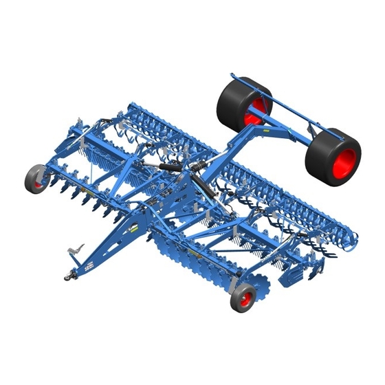
- Page 1 OPERATING INSTRUCTIONS COMPACT DISC HARROW RUBIN 12 KUA Rubin 12/800 KUA Rubin 12/950 KUA en-GB | Item no. 17514282 | BA 01/2023-03...
- Page 2 Pass these instructions to all users / owners. Original instructions © 2023 | This documentation is copyright protected. The copyright remains with LEMKEN GmbH & Co. KG, Weseler Strasse 5, D-46519 Alpen. The texts, diagrams and drawings must not be duplicated, distributed or disclosed in any other way,...
-
Page 3: Table Of Contents
Table of contents Table of contents About these instructions............................1 1.1 Introduction................................. 1 1.2 Target groups..............................3 1.3 Applied presentations............................. 3 1.3.1 Signal words and hazard statements...................... 3 1.3.2 Symbols and text markings........................4 1.3.3 Direction specifications..........................4 1.4 Further applicable documents........................5 Safety.................................... - Page 4 Table of contents 5.3 Preparing the lighting equipment for road travel................33 Operation................................... 35 6.1 Basic operation..............................35 6.1.1 Folding machine............................35 6.1.2 Operate the stand............................36 6.2 Changing the setup state..........................36 6.2.1 Mount the weed harrow........................... 36 6.3 Adjusting the machine..........................37 6.3.1 Depth adjustment............................
- Page 5 Table of contents 9.3.3 Grease components............................ 66 9.4 Work instructions............................67 9.4.1 Replace the concave discs........................67 9.4.2 Re-adjusting the locking device of the outer concave discs............68 9.4.3 Replace the scrapers of the flexring roller..................69 9.4.4 Replacing the harrow tines of the rebound harrow................ 69 9.4.5 Replacing the levelling harrow.......................
- Page 6 Table of contents en-GB | Item no. 17514282 | BA 01/2023-03...
-
Page 7: About These Instructions
About these instructions About these instructions Introduction These operating instructions are important and belong to the machine's scope of delivery. These operating instructions must be available to the user at the place of use. Always read chapter "Safety" before using the machine for the first time. - Page 8 About these instructions Validity range These operating instructions describe operation of the machine after initial commissioning by the LEMKEN sales partner and handover to the operator. Prior to operation, initial commissioning and instruction in operation, setting/adjustment and maintenance must have been carried out.
-
Page 9: Target Groups
About these instructions Target groups The target groups of these operating instructions are operators, users and service personnel of the machine. The target groups must meet the requirements for the qualification of the personnel. Ä Chapter 2.2 ‘Requirements of operators, users and service personnel’ on page 7. -
Page 10: Symbols And Text Markings
About these instructions 1.3.2 Symbols and text markings Symbol, text Meaning marking In front of and in texts Marking for routine maintenance tasks ● Activities that demand the help of service staff. Listing Position numbers [1], Example: ‘Settings’ Software element Example: [OK] Softkey, key, switch and button [kg]... -
Page 11: Further Applicable Documents
The documents are regularly updated and brought into line with any changes. The latest versions of the documents can be found in the LEMKEN Online Information System (LEONIS). Users can access LEONIS directly via the QR code or the LEMKEN website. -
Page 12: Safety
Safety Safety Machine limits Intended use The machine is used for soil cultivation on agricultural land. The machine is used for soil cultivation on agricultural land. It may only be used in accordance with the recognised rules of good agricultural practice. The permitted working depth is limited to the cultivatable soil horizons. -
Page 13: Requirements Of Operators, Users And Service Personnel
Safety Hazardous area The machine and the area in the immediate vicinity of the machine is deemed a hazardous area. This includes the space over the entire width, length and height of the machine, as well as an additional safety distance of two metres to the machine. -
Page 14: General Safety Information
Safety General safety information Operating instructions The operating instructions are part of the machine. The machine is intended exclusively for use in accordance with these operating instructions. Applications of the machine not described in these oper‐ ating instructions may result in personal injury or death or property damage. - Page 15 Safety Safety equipment Existing and fully functional safety devices protect against death or serious personal injury. Keep the labels legible and renew them, if necessary. ► Replace damaged safety devices. ► Install dismantled safety devices before commissioning. ► Move the safety devices to the protective position. ►...
- Page 16 Safety Hydraulic assembly The hydraulic assembly might be under high pressure. Hydraulic oil leaking under pressure can penetrate through the skin into the body. Injury to body parts, face, eyes and unprotected skin may result. The hydraulic assembly may be hot. The hydraulic oil is harmful to health.
-
Page 17: Safety Information On Hazardous Areas Of The Machine
Safety Safety information on hazardous areas of the machine Area between the tractor and When standing between the tractor and machine, there is a risk due to machine tractor movements or sudden machine movements. Secure the tractor against rolling away. ►... - Page 18 Safety Moving hazardous area The hazardous area of the machine during operation. Moving hazardous area The hazardous area includes the area in driving direction across the entire width of the machine. There must be NO persons in the hazardous area. If there are persons in the hazardous area, may result in death or injury to persons.
- Page 19 Safety Folding range Hazardous areas when folding the implement There should be NO persons present in the folding range. If persons are present in the folding range, it may result in death or serious injury. Lateral sections may, due to their height touch overhead lines during the folding processes and cause flashovers.
-
Page 20: Safety Information On Structural Modifications
Safety Safety information on structural modifications Structural modifications Structural modifications and extensions can impair the functionality and operational safety of the machine. This may result in death or injuries. Auxiliary equipment and spare parts must comply with the manufactur‐ er's requirements. Modifications and conversions may only be carried out with the ►... - Page 21 Safety Behaviour during flashover of over‐ Flashovers cause high electrical voltages on the outside of the tractor- head lines machine combination. Large voltage differences occur on the ground around the tractor-machine combination. Large steps, lying down or supporting yourself on the ground may cause life-threatening electrical currents (step voltage).
- Page 22 Safety Road travel The user operates the machine via control elements such as tractor control units, touch screen, buttons or joystick. Touching the control elements may trigger functions and machine movements, even if touching the control elements was not intended. Disabling machine functions before driving on the road.
-
Page 23: Design And Description
Design and description Design and description Machine overview INFORMATION Depending on the equipment of the machine and country-specific requirements, the assembly groups described below may be present on the machine. Drawbar with hitch and connections Scale of the hydraulic depth adjustment Concave discs Hydraulic ram for moving the lateral parts Levelling harrow... -
Page 24: Machine Safety
Design and description Further information about the type plate: Ä Appendix A ‘Type plate variants’ on page 86 Machine safety 3.2.1 Position of the label 3.2.2 Meaning of the labels This section explains the information and warning signs that have been affixed to the machine. - Page 25 Design and description Reading the operating instructions Incorrect use or operation of the machine can result in death or serious injury. Before commissioning: Read and observe the operating instructions. ► Follow the instructions for action. ► Turn off the engine A tractor with the engine running can cause unintentional movements.
- Page 26 Design and description Area between the tractor and machine A tractor with the engine running can make or cause unintentional movements. This will result in death or serious injury. When the tractor is running: Do NOT remain in the area between the tractor and machine. ►...
-
Page 27: Safety Devices
Design and description Jack positioning points Positioning points for jack Lifting points for fork-lift truck Lifting points for fork-lift truck High-pressure cleaning prohibited Do not use a high-pressure cleaner for cleaning. Hydraulic equipment Connection overview of hydraulic hoses P1/T1 - Folding* P2/T2 - Trailer* P3/T3 - Hydraulic depth adjustment P5/T5/LS - iQblue Contour (contour adjustment) - Page 28 Design and description Front lighting equipment Example of front lighting equipment LED indicator Reflecting film - yellow Rear lighting equipment Example of rear lighting equipment LED indicator Reflecting film - red Reflecting film - orange LED rear light Warning board Depending on national regulations, a warning board may be required for slow-moving vehicles.
-
Page 29: Hydraulic Drawbar
Design and description 3.2.3.2 Stabilisation Stand - hydraulic drawbar The wheel chocks are carried on the machine in the area of the lamp holder when the machine is mounted. 3.2.3.3 Safety chain For machines without a braking system, a safety chain may be required, depending on the national regulations. -
Page 30: Solo Axle
Design and description Solo axle The solo axle is only used to transport the implement and to insert and lift the implement when working in the field. Use in conjunction with other mounted implements is not permitted. iQblue Contour Overview Contour adjustment takes place automatically when the iQblue Con‐... -
Page 31: Trailer
Design and description LPS control Position of the LEDs on the implement The LED display shows current processes and the status of the job computer, e.g. error codes. There are six LEDs, each with a different meaning. Error code display of the sensors Signal for the start and end of the error code Software activity Retract working section cylinder (side independent) -
Page 32: Working Tools
Design and description Working tools Tool Application/Special feature Concave discs The implement is equipped with two rows of serrated concave discs. The concave discs are protected against overloads by the automatic over‐ load safety devices. The outer concave discs offer infinitely variable adjustment of the working depth. -
Page 33: Commissioning
Commissioning Commissioning Checking suitability of the tractor WARNING Risk of accident due to unsuitable tractor If the tractor is not suitable for the machine, compo‐ nents of the machine may be overloaded and the tractor- machine combination may not be steered safely. This may result in accidents with injuries or death of persons or damage to the machine. -
Page 34: Preparing The Tractor
Commissioning Preparing the tractor Keep the tractor documentation The tractor is prepared before attaching the machine. For this purpose, ready the user must carry out various checks and adjustments. The following information about the tractor is required: Air pressure of tyres Checklist Tyres Observe the instructions of the tractor manufac‐... - Page 35 Commissioning Checklist The tractor is suitable for operating Ä Chapter 4.1 ‘Checking suita‐ the machine. bility of the tractor’ on page 27 The tractor is prepared. Ä Chapter 4.2 ‘Preparing the tractor’ on page 28 The machine is mounted ready for use and is in technically perfect con‐...
-
Page 36: Attaching The Machine
Commissioning 4.3.2 Attaching the machine Attach the implement to the tractor 1. Move the tractor straight back in front of the implement ð The distance is approx. 20 cm. INFORMATION: If horizontal attachment of the implement is not possible: – Adjust the height of the traction device on the tractor. - Page 37 Commissioning 3. Connect hydraulic hoses to the tractor. Make certain they are assigned correctly. Note the hydraulic system labels. 4. Check whether the volumetric flow for folding is adjusted to at least 70 l/min. 5. Connect the electric lines to the tractor. 6.
-
Page 38: Road Travel
Road travel Road travel Information on road travel Laws on driving on public roads differ in many countries. Pay particular attention to local laws and regulations regarding the ► following points: Driving on public highways Maximum permissible transport height Maximum permissible transport width Maximum permissible transport weight Lighting equipment Markings... -
Page 39: Preparing The Lighting Equipment For Road Travel
Road travel Checklist Working depth Adjust the working depth of the imple‐ Ä Depth adjustment, see page 37 ment (red pointer) to position "5". Control units of the Observe the instructions of the tractor Ä Further applicable documents, see tractor hydraulics manufacturer. - Page 40 Road travel Checking electric lines and proper functioning 1. Connect the connector of the lighting equipment to the socket on the tractor. 2. Test the electric line between the tractor and the machine. 3. Test the lighting equipment. Testing the lighting equipment 1.
-
Page 41: Operation
Operation Operation Basic operation 6.1.1 Folding machine Folding machine out Preconditions: √ NO overhead lines in the folding range √ NO persons in the folding range √ Tractor has stopped. √ Machine is lifted fully at the front and rear. 1. -
Page 42: Operate The Stand
Operation 6.1.2 Operate the stand Fold the stand 1. Unlock the stand Remove the pin 2. Fold in/out the stand. 3. Secure the stand. Stand Folded in: Mount the pin in the holder Folded out: Insert the pins in the holes Secure the pin with the linch pin. -
Page 43: Adjusting The Machine
Operation 1. Position both U-bolts on the leg of the roller. 2. Mount the brackets of the harrow segment. 3. Install and tighten the washers and nuts Ä Appendix B ‘Tight‐ ening torques screws ’ on page 88 4. If necessary, Ä Adjust the weed harrow, page 47. U-bolts Roller leg Harrow holder... -
Page 44: Adjust The Outer Concave Discs
Operation 1. Set shallowest working depth. ð Red pointer is at position 2. Lower implement on horizontal ground on the rollers. 3. Adjust the hydraulic drawbar. ð The working depth of the front and rear concave disc row is the same. Depth adjustment (red arrow) 4. -
Page 45: Iqblue Contour Prepare And Calibrate
Operation 6.3.3 iQblue Contour Prepare and calibrate 6.3.3.1 Preparing the tractor-machine combination Precondition: √ Machine is mounted. 1. Fold out and lower the machine. 2. Secure the tractor-machine combination to prevent it from rolling away. 3. Disconnect the electrical connection to the job computer. DANGER: Danger of death due to unintentional machine move‐... - Page 46 Operation 6.3.3.2.2 iQblue Contour Activate or deactivate iQblue Contour Activate Precondition: √ Ä Chapter 6.3.3.1 ‘Preparing the tractor-machine combination’ on page 39 1. Remove the pin Start the tractor. Unlock the hydraulic control units Use the control unit to move the folding cylinder to a position that ensures the pin can be pulled without resistance.
- Page 47 Operation iQblue Contour Deactivate Precondition: √ Ä Chapter 6.3.3.1 ‘Preparing the tractor-machine combination’ on page 39 1. Close the shut-off valve on the hydraulic ram. Shut-off valve hydraulics iQblue 2. Remove the pin Contour Start the tractor. Unlock the hydraulic control units Use the control unit to move the folding cylinder to a position that ensures the pin can be pulled without resistance.
- Page 48 Operation 6.3.3.3 iQblue Contour Calibrating 6.3.3.3.1 Automatic calibration Overview on the implement Position of the job computer Position of the LEDs Position of the button Status display in calibration mode Error log of the sensors Status display Meaning Start signal and end signal of the error messages Saving of the current calibration value lights up.
- Page 49 Operation INFORMATION The process is aborted if an error occurs in the corre‐ sponding sensors. The yellow LEDs of the faulty function and the red LED flash. – If necessary, have the error eliminated by a service technician. Ä For information on the error codes, see page 72. Preconditions: √...
- Page 50 Operation 10. Press the button for one second. ð LED lights up for two seconds. The value has been saved when the LED no longer lights 11. Disconnect the job computer from the power supply. 12. Reconnect the job computer to the power supply. Restart. ð...
- Page 51 Operation If the implement works too deep on one side or in the middle, a manually adjusted stroke length on the depth adjustment cylinder can compensate for the working depth. Compensate the working depth on Initial situation: The implement operates, e.g., too deep on the outer the left or right left-hand side.
-
Page 52: Adjust The Rebound Harrow
Operation Compensate working depth in the Initial situation: Implement operates too deep in the middle. middle Precondition: √ Ä Chapter 6.3.3.1 ‘Preparing the tractor-machine combination’ on page 39 Adjust the outer depth adjustment cylinders : 1. Adjust the outer depth adjustment cylinders . Ä... -
Page 53: Adjust The Levelling Harrow
Operation 1. Remove the screw 2. Position the harrows between the holes that belong to the desired distance. 3. Insert the screw in the holes. 4. Secure the screw with the nut. Screw 6.3.5 Adjust the levelling harrow Holes The levelling harrow refills the grooves left by the rear concave discs with soil. -
Page 54: Adjust Side Shields
Operation Adjusting the angle Turn the screw with the spanner. ► Clockwise = flat angle Anticlockwise = steep angle ð The yoke moves up/down with the harrow tube. The angle of the harrow changes. Screw 6.3.7 Adjust side shields Yoke Length adjustment The user can adjust the length of the side shields in two positions to match the distance of the rebound harrows. -
Page 55: Working With The Machine
Operation Working with the machine 6.4.1 Standard procedure 1. Bring the tractor implement combination into position. 2. If present, remove the safety guards. 3. Fold out machine. 4. Dismantle the lighting equipment. 5. Set the machine. 6. During forward travel, insert the machine into the soil. 7. -
Page 56: Working On Uneven Terrain And On A Slope
Operation 6.4.3 Working on uneven terrain and on a slope WARNING Risk of accident due to the implement tipping over If the folded-in implement is pulled over uneven terrain or on a slope, the implement may tip over in borderline situations. -
Page 57: Cleaning And Care
Cleaning and care Cleaning and care Cleaning with high-pressure cleaner The user can clean the machine with the high-pressure cleaner. When cleaning, the user must observe the following: ATTENTION Damage due to cleaning with a high-pressure cleaner Components may be damaged when cleaning with a high-pressure cleaner. -
Page 58: Detaching Machine
Detaching machine Detaching machine Detaching the machine 1. If the machine is to be parked in the folded in position: Fold in the machine before detaching. Ä Chapter 6.1.1 ‘Folding machine’ on page 35 Ä ‘Folding machine out’ on page 35 Ä... - Page 59 Detaching machine 16. Slowly and carefully move the tractor and the machine apart. 17. Prior to extended breaks or winter storage: Clean and lubricate the machine. At machines without a hydraulic-mechanical transport locking device: Secure the lateral parts against folding out, e.g. with lashing straps.
-
Page 60: Maintenance And Repair Work
Maintenance and repair work Maintenance and repair work Maintaining the machine properly Personnel Certain activities, e.g. working on hydraulic hoses, should only be car‐ ried out by service personnel. These tasks are: Highlighted with the symbol Marked in the SERVICE PERSONNEL column in the maintenance schedule 9.1.1 Preparations... -
Page 61: During The Maintenance And Repair
Maintenance and repair work 9.1.2 During the maintenance and repair To prevent accidents or injuries: Wear protective equipment. ► Use auxiliary equipment, e.g.: ► Suitable tools Climbing aids Supporting elements For dismantling and mounting heavy components: ► Use hoisting gear. Check nuts and screw heads etc. - Page 62 Maintenance and repair work Chap. Task to execute 9.2.4 Check marking ● 9.2.4 Checking safety sticker ● 9.2.5 Checking hydraulic hoses ● 9.2.5 Replacing hydraulic hoses ● ● 9.2.5 Checking hydraulic connections ● 9.2.5 Check the hydraulically unlockable nonre‐ ● turn valves 9.2.6 Checking connector plugs and cables...
-
Page 63: Tractor Connection
Maintenance and repair work 9.2.2 Tractor connection Check the ball-shaped coupling or the drawbar eye Personnel: Service personnel 1. Visual inspection by the user Wear Damage Peculiarities when driving Have a damaged, deformed or worn ball-shaped coupling or drawbar eye replaced immediately. 2. -
Page 64: Checking Safety Devices
Maintenance and repair work Checking air pressure WARNING Risk of accident due to incorrect air pressure Excessive air pressure in the tyres may cause them to burst. Insufficient air pressure can lead to overloading of the tyres. This will have a negative influence on accu‐ rate follow-on of the machine. -
Page 65: Hydraulics
Maintenance and repair work 9.2.5 Hydraulics Checking hydraulic hoses 1. Check hydraulic hoses for damage and leakages. ð Replace damaged or defective hydraulic hoses immedi‐ ately. 2. Check date of manufacture of the hydraulic hoses. ð Have hydraulic hoses replaced at the latest after 6 years. Replacing hydraulic hoses Personnel: Service personnel... -
Page 66: Electrics
Maintenance and repair work Check the hydraulically unlockable nonreturn valves Folded in implement: Observe correct functioning and condition of ► the nonreturn valves at the folding cylinders. The implement remains permanently in transport position. The lateral parts do NOT fold out automatically WITHOUT any user intervention. -
Page 67: Rollers
Maintenance and repair work Check the overload safety units of the concave discs 1. Check the bolted connections. ð Retighten loose bolted connections. 2. Check the bearing for wear. ð Replace worn bearings of the overload units. Bearing overload safety unit Checking soil cultivation implements Visual inspection ►... -
Page 68: Checking The Scraper Of The Trapeze Packer Roller
Maintenance and repair work 9.2.8.2 Checking the scraper of the trapeze packer roller 1. Check the distance between the scraper and the roll sleeve Turn the roller through 360°. INFORMATION: The scraper must not touch the roll sleeve at any position. -
Page 69: Lubricating
Maintenance and repair work Lubricating 9.3.1 Lubrication schedule INFORMATION The lubrication points are colour coded on the machine. Chap. Task to execute 9.3.2 Lubricate the drawbar eye ● ● 9.3.2 Lubricate wheel bearing ● ● 9.3.2 Lubricate the hydraulic ram on the folding mechanism ●... -
Page 70: Lubricate Components Via Grease Nipples
Maintenance and repair work 9.3.2 Lubricate components via grease nipples Lubricate the drawbar eye ► Lubricate 1 lubricating point at the drawbar eye Lubricating point Lubricate wheel bearing ► Lubricate 1 lubricating point at the wheel bearing Wheel bearing lubricating point Lubricate the hydraulic ram on the folding mechanism Lubricate 2 lubricating points on both hydraulic rams... - Page 71 Maintenance and repair work Lubricate the hydraulic ram on the trailer ► Lubricate 2 lubricating points on the hydraulic ram Lubricate folding joints - without iQblue Contour ► Lubricate 4 lubricating points in the joints of the basic frame. Folding joints Lubricate folding joints with iQblue Contour ►...
-
Page 72: Grease Components
Maintenance and repair work Lubricate bearings at the drawbar and basic frame 1. Lubricate 2 lubricating points in the bearings of the drawbar. 2. Lubricate 2 lubricating points in the bearings of the arm. View from below Bearing at the drawbar 9.3.3 Grease components Bearing at the arm... -
Page 73: Work Instructions
Maintenance and repair work Work instructions 9.4.1 Replace the concave discs WARNING Danger due to the lowering and folding out of com‐ ponents Danger of death when performing work underneath raised components or next to swivelled in components and implements. Preconditions: √... -
Page 74: Re-Adjusting The Locking Device Of The Outer Concave Discs
Maintenance and repair work 9.4.2 Re-adjusting the locking device of the outer concave discs Checking the outer concave discs with hydraulic folding 1. The locking hook on the hydraulic ram must grip free of play behind the hexagon bolt 2. The hexagon bolt must be positioned on the flank of the locking hook 3. -
Page 75: Replace The Scrapers Of The Flexring Roller
Maintenance and repair work 9.4.3 Replace the scrapers of the flexring roller Target: Avoid consequential damage to the implement caused by fallen-off scrapers. 1. Dismantle worn scrapers . 2. Mount new scrapers. 3. Tighten the screw to 93 Nm. 9.4.4 Replacing the harrow tines of the rebound harrow CAUTION Stored mechanical energy... -
Page 76: Replacing The Levelling Harrow
Maintenance and repair work 9.4.5 Replacing the levelling harrow 1. Fold out lateral parts of folding machines. 2. Lift the machine and secure it against unintentional lowering. 3. Secure the tractor-machine combination to prevent it from rolling away. 4. Remove the ignition key. 5. -
Page 77: 10 Troubleshooting And Error Correction
Troubleshooting and error correction 10 Troubleshooting and error correction 10.1 Finding and eliminating errors correctly DANGER Serious crush injuries A machine with a high dead weight can move down‐ wards independently. Serious crush injuries and puncture wounds caused by sharp components, as well as deep lacerations caused by sharp-edged components, can lead to life-threatening harm. -
Page 78: Error - Cause - Remedies At A Glance
Troubleshooting and error correction When troubleshooting and elimi‐ nating errors To prevent accidents or injuries: 1. Wear protective gear. 2. Use the following instruments: Suitable tools Climbing aids Supporting elements 3. For dismantling and mounting heavy components: Use hoisting gear. 4. - Page 79 Troubleshooting and error correction Flashing sequence of the red Error code trigger and green LEDs 3x red, 2x green Roller sensor, left 4x red, 2x green Roller sensor, right 5x red, 2x green Angle sensor field, left 6x red, 2x green Angle sensor field, right The red LED flashes permanently as long as the error has not been eliminated.
-
Page 80: 11 Shutdown And Disposal
Shutdown and disposal 11 Shutdown and disposal 11.1 Final decommissioning ENVIRONMENTAL PROTECTION Do NOT leave machine parts exposed to weather condi‐ tions for an extended period, as operating materials, etc. could be released into the environment. Precondition: √ Further use of the machine within the meaning of these instruc‐ tions is no longer intended. -
Page 81: Recycling And Disposal
Shutdown and disposal 11.2 Recycling and disposal Special knowledge is required for disposal of machine parts or oper‐ ating materials. 1. Assign qualified specialists for disposal. 2. Recycle machine parts. 3. Dispose of auxiliary materials and operating materials in an envi‐ ronmentally responsible manner. -
Page 82: Technical Data
Technical data 12 Technical data 12.1 Dimensions Rubin 12/800 KUA Rubin 12/950 KUA Transport width* , Maximum [mm] 4500 5800 Transport width* , Minimum [mm] 4500 5800 Transport length* , Maximum [mm] 8800 8800 Transport length* , Minimum [mm] 8700 8700 Transport height* , Maximum [mm] 4350... -
Page 83: Connection Data
Technical data Tractor power requirements Tractor Rubin 12/800 KUA Rubin 12/950 KUA Permissible tractor power 360...640 428...760 min..max. [HP] ([kW]) (265...470) (314...560) Power requirements on the hydraulic system of the tractor Rubin 12/800 KUA Rubin 12/950 KUA Required pressure in the hydraulic system of the tractor for rams of the oil hydraulics [bar] on the implement side Permissible pressure, max. -
Page 84: Hydraulic Connections
12.5 Noise, airborne sound £70 dB(A) Noise level of the machine while working 12.6 Operating materials Operating material Rubin 12 KUA Hydraulic oil [type] HLP 46 according to ISO 4406 21/19/16 12.7 Tyres and wheels Load capacity [kg] Rolling Air pres‐... -
Page 85: Connecting Systems At The Machine
Technical data 12.8 Connecting systems at the machine Connecting systems according to implement variants Connecting Standard / Size Rubin 12/800 KUA Rubin 12/950 KUA system Drawbar eye ISO 21244 / Cat.4 ● Drawbar eye ISO 21244 / Cat.5 ● Ball joint drawbar eye ISO 21244 / Cat.4 ●... -
Page 86: Permissible Roller Types
Technical data 12.9 Permissible roller types Permissible roller types Double profile ring roller Double roller DRF 400/400 DRR 400/400 DRR 540/400 Flexring roller FRW 540 Packer single roller PEW 600 en-GB | Item no. 17514282 | BA 01/2023-03... -
Page 87: Index
Index Index Depth adjustment ......26 Detach Air pressure Machine ......52 Check . - Page 88 Index Levelling harrow Adjust ......47 High-pressure cleaner ..... 51 Lighting equipment .
- Page 89 Index Limits ....... 6 Maintain properly ..... . 54 Qualification Service personnel .
- Page 90 Index Setup state Type plate changing ......36 Machine data ......2 Shutdown .
-
Page 91: Appendix
Appendix Appendix en-GB | Item no. 17514282 | BA 01/2023-03... -
Page 92: A Type Plate Variants
19 Type / Variant / Version the type plate. 20 Technical conditions Permissible total mass [kg]* 21 QR code to call up LEONIS (LEMKEN Online Infor‐ 10 Permissible drawbar load [kg] (axle 0) mation System) 11 Permissible axle load [kg] (axle 1) - Page 93 Type plate variants en-GB | Item no. 17514282 | BA 01/2023-03...
-
Page 94: B Tightening Torques Screws
Tightening torques screws Tightening torques screws Bolted connections, general principles The following tightening torques refer to screw connections not spe‐ cifically mentioned in these mounting instructions. Special tightening torques are indicated in the text. Identify screw connection: – Identification on the screw head –... - Page 95 The friction coefficient of 0.14 ... 0.15 must be complied with. Never tighten with an impact wrench Tightening torques for bolted connections The following tightening torques apply with all bolted connections used by LEMKEN, unless specified otherwise: Screws and nuts made of steel Diameter Strength category 8.8 [Nm*]...
- Page 96 Tightening torques screws Diameter Strength category 8.8 [Nm*] 10.9 [Nm*] 12.9 [Nm*] 1245 1450 1121 1570 1892 1958 2753 3304 * µ = 0.09 Diameter Strength category 8.8 [Nm*] 10.9 [Nm*] 12.9 [Nm*] M8 x 1 22.8 32.0 38.4 M10 x 1 40.9 57.5 68.9...
- Page 97 Tightening torques screws Screws and nuts made of stainless steel Diameter [Nm*] A2-70 A4-80 11.5 19.0 25.5 38.0 51.0 65.0 87.0 * µ = 0.14 Tightening torques for wheel bolts and wheel nuts Implements Diameter / thread [Nm] Every M14 x 1,5 Every M18 x 1,5 Every...
- Page 98 The tightening torques are calculated for the friction values µ specified in the tables. The required tightening torque deviates: – If any screws other than LEMKEN original screws are used. – If screws are re-used. Only use LEMKEN original screws!
- Page 100 LEMKEN GmbH & Co. KG Weseler Strasse 5 D-46519 Alpen Telephone: +49 2802 81-0 Fax: +49 2802 81-220 Email: info@lemken.com Internet: www.lemken.com...
Need help?
Do you have a question about the RUBIN 12 KUA and is the answer not in the manual?
Questions and answers